Kawasaki Diesel MULE 4010 TRANS 4x4 (KAF950G9). Manual - part 90
 

  Index      Engines     Kawasaki Diesel MULE 4010 TRANS 4x4 (KAF950G9) - service manual


Search            


Content   ..  88  89  90  91   ..


Kawasaki Diesel MULE 4010 TRANS 4x4 (KAF950G9). Manual - part 90


14-14 SUSPENSION

Leaf Springs and Dampers

Leaf Spring Installation

•

When installing the rubber bushings to the leaf spring,
lubricate them with a soap and water solution.

NOTICE

Do not use engine oil or petroleum distillates to lu-
bricate the bushings because they will deteriorate
the rubber.

•

Install the rear wheel temporarily and ground it to load the
suspension during the mounting nut tightening.

•

Tighten:

Torque - Leaf Spring Mounting Bolts (Front): 98 N·m (10.0

kgf·m, 72.3 ft·lb)

Leaf Spring Mounting Nuts (Rear): 59 N·m (6.0

kgf·m, 44 ft·lb)

Rear Shock Absorber Mounting Nuts: 59 N·m (6.0

kgf·m, 44 ft·lb)

•

Apply liquid gasket to the threads of the leaf spring
bracket.

Sealant - Three Bond: 1364D

•

Replace the damper bracket mounting nuts with new
ones.

•

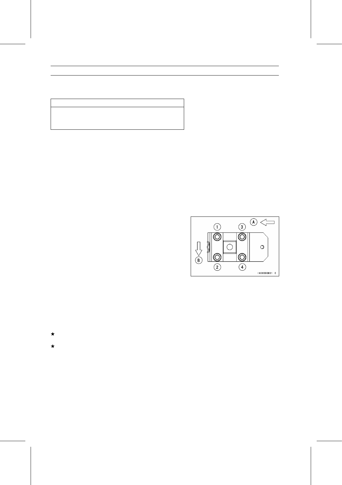
Tighten the damper bracket mounting nuts in the order as
shown in the figure.

Front [A]
Outside [B]

Torque - Damper Bracket Mounting Nuts:

First: 20 N·m (2.0 kgf·m, 15 ft·lb)
Second: 44 N·m (4.5 kgf·m, 32 ft·lb)
Final: 59 N·m (6.0 kgf·m, 44 ft·lb)

•

Apply brake fluid to the brake pipe nipple threads.

•

Tighten:

Torque - Brake Pipe Nipples: 18 N·m (1.8 kgf·m, 13 ft·lb)

•

Bleed the brake line (see Brake Line Air Bleeding in the
Brakes chapter).

Leaf Spring Inspection

•

Visually inspect the leaf spring for breaks or distortion.
If the leaf spring is damaged in any way, replace it.

•

Check the rubber bushings in the mounts and the damper.
Replace any bushings or damper that are worn, cracked,
hardened, or otherwise damaged.

STEERING 15-1

15

Steering

Table of Contents

Exploded View...................................

15-2

Specifications ....................................

15-4

Special Tools .....................................

15-5

Steering Wheel and Main Shaft

Assembly ........................................

15-6

Steering Wheel Position

Adjustment ................................

15-6

Steering Wheel Free Play

Inspection..................................

15-6

Steering Wheel Centering............

15-6

Steering Wheel and Steering

Shaft Removal (KAF950G9

∼

GC/HA)......................................

15-7

Steering Wheel and Steering

Shaft Installation (KAF950G9

∼

GC/HA)......................................

15-8

Steering Wheel and Steering

Shaft Removal (KAF950GD).....

15-10

Steering Wheel and Steering

Shaft Installation (KAF950GD)..

15-11

Steering Gear Assembly....................

15-13

Steering Gear Assembly

Removal ....................................

15-13

Steering Gear Assembly

Installation .................................

15-14

Steering Gear Preload

Adjustment ................................

15-16

Tie-Rod Length Adjustment .........

15-16

Steering Joint Dust Boot

Inspection..................................

15-16

Steering Knuckles..............................

15-17

Steering Knuckle Removal...........

15-17

Steering Knuckle Installation........

15-17

Knuckle Bearing Removal............

15-18

Knuckle Bearing Installation.........

15-18

Knuckle Joint Removal ................

15-19

Knuckle Joint Installation .............

15-19

EPS (Electric Power Steering)

System............................................

15-20

EPS System Servicing

Precautions ...............................

15-25

EPS System Troubleshooting

Outline.......................................

15-26

Inquiries to Rider..........................

15-30

Self-diagnosis Outline ..................

15-30

Self-diagnosis Procedure.............

15-31

Service Code Reading .................

15-32

Service Code Erasing ..................

15-32

Service Code Erasing

Procedures................................

15-35

EPS Neutral Position Registration

15-37

Power Supply Voltage Abnormal

(Service Code 11,12) ................

15-40

EPS Neutral Position

Unregistration (Service
Code 31) ...................................

15-40

Current Sensor Inspection

(Service Code 32) .....................

15-40

FET (Field Effect Transistor)

Inspection (Service Code 33)....

15-41

Internal Relay Inspection (Service

Code 34) ...................................

15-41

CPU (Central Processing Unit)

Inspection (Service Code 35)....

15-42

Direction Distinction Circuit

Inspection (Service Code 36)....

15-42

Boosting Transformer Circuit

Inspection (Service Code 37)....

15-42

EPS Torque Sensor Inspection

(Service Code 51) .....................

15-43

EPS Motor Inspection (Service

Code 61) ...................................

15-44

EPS Warning Indicator Light

(LED) Removal..........................

15-45

EPS Warning Indicator Light

(LED) Inspection .......................

15-46

EPS ECU Removal ......................

15-47

EPS ECU Installation ...................

15-48

EPS ECU Power Supply Voltage

Inspection..................................

15-49

EPS Motor Removal ....................

15-50

EPS Torque Sensor Removal ......

15-51

EPS Unit Removal .......................

15-51

EPS Unit Installation ....................

15-53

Speed Sensor Removal/Installa-

tion ............................................

15-55

Speed Sensor Inspection.............

15-55

EPS ECU Relay Removal/Instal-

lation..........................................

15-56

EPS ECU Relay Inspection..........

15-56

Diodes Removal/Installation ........

15-56

Diodes Inspection ........................

15-57

EPS Fuse 40 A Removal .............

15-57

EPS Fuse 7.5 A Removal ............

15-58

Fuse Installation...........................

15-58

Fuse Inspection............................

15-58

15-2 STEERING

Exploded View

STEERING 15-3

Exploded View

Torque

No.

Fastener

N·m

kgf·m

ft·lb

Remarks

1 EPS Unit Mounting Bolts

20

2.0

15

2 Rack Guide Spring Cap Locknut

39

4.0

29

3 Steering Gear Assembly Bracket Bolts

52

5.3

38

L

4 Self-lock Nut

52

5.3

38

R

5 Strut Clamp Nuts

98

10.0

72.3

6 Tie-Rod End Locknuts

44

4.5

32

7 Tie-Rod End Nuts

34

3.5

25

8 Universal Joint Clamp Bolts

20

2.0

15

9. KAF950G9

∼ GC/HA

10. Apply grease on contact plate.

G: Apply grease.

L: Apply a non-permanent locking agent.

R: Replacement Parts


Content   ..  88  89  90  91   ..