Technology of watch production - part 106
initial p o s ition, and the dots will form a line inclined to the right. If, on
the othe r hand, the watch lags , the line of dots will be inclined to the left.
The daily error for the watch is determined from the slope of the line, with
the aid of a special rotatable scale and the gene ral shape of the line (it is
not always straight ) makes it pos s ible to draw conclusions as to the probable
watch defects . The error determined by the instrument is not the actual
2 4 - hour erro r but a relative error which corresponds to the condition of the
watch m ovement at the m oment of testing. If the daily erro r is m ore than
·
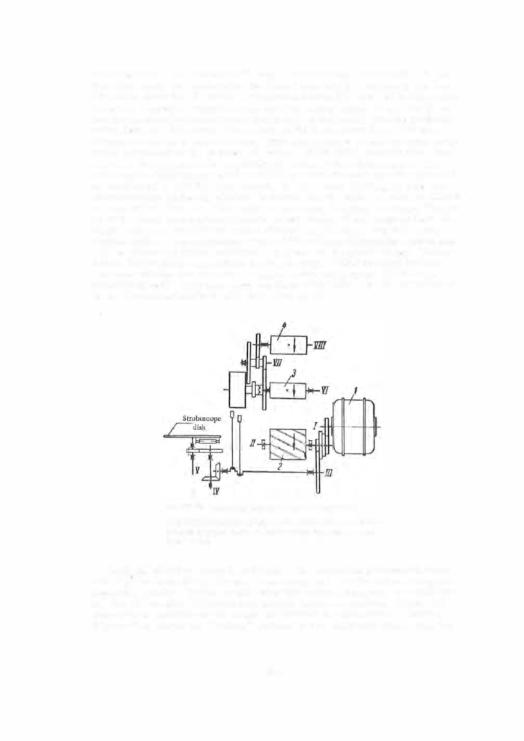
± 1 0 min, the inspection is conducted by means of the stroboscop e . The
s trobos cope disk (Figure 6 3 ) is rotate d by a synchronous electric m otor at
a speed equal to half the drum speed. A neon l amp , l ighting up when the
electromagnet closes its c ircuit, is fastened to the disk. A s cale is plac ed
in front of the disk and, if the watch is accurate, the lamp is always lighted
up at the same disk pos ition relative to the scal e . I f the watch i s fas t, the
lamp flashes on the disk will m ove clockwise; if it lags , they will m ove
anticlockwise . The preliminary test of the balance - hairspring system (dur
ing the ass embly ) is also conducted by m eans of the strobos cope. The ac
curate final test is recorded on the paper s trip . Chronometers and very
accurate watches are inspected using a slower s trip spe e d ( 1 / 1 0 of the
s tandard spee d ) . This increas es the slope o f the line , and the result read
on the instrument scal e should be divided by 1 0 .
r!GURE
63. Kinematic diagram of the P-12 instrument:
1-synchronous electric motor, 2 -drum with helical projections;
3-paper-strip feed drum; 4-carbon-ribbon feed drum; 5-stro
boscope disk.
A nalysis of watch-timer recordings . The recording pattern can se rve
not only for determ ining the watch accuracy, but also for determining the
ass embly quality. Before conside ring this aspect, howeve r, we must have
an idea of the noise pattern acc ompanying balance operation. F igure 6 4
shows three positions o f the l ever es capem ent in which noise is produc e d .
F i gure 6 4 , a shows the "locking" pos ition of the pallet and wheel when the
42 1