Technology of watch production - part 104
 

  Index      Books     Technology of watch production (Tarasov) 1964 year


Search            


Content   ..  102  103  104  105   ..


Technology of watch production - part 104


Variation  in bearing friction. 

The  largest  variations  in  the  amplitude 

occur in  the  following two  cas e s :   1 )   when  the  watch  position  is  changed 
from  horizontal  to  vertical;  2 )   at maximum  and  m inimum  spring tension. 

The  decrease  in amplitude  accompanying  a  change  from horizontal  to 

vertical  pos ition  of the watch  is  due  to  the  increase  in the friction moment 
in  the  bearings .  In  the  horizontal  position  (dial  up  or  down )  the  balance 
staff  rests  with its  sphe rical  heel  on  the  endstone  face  and the  friction  m o ­
ment i s   very  small  be caus e  of the  very  small  friction  radius .  In  vertical 

pos ition  of  the  watch  the  balance  rests  with its  two  staff j ournals  on the 

cylindrical  surface  of  the  jewel  bearings .  The  friction m om ent  is  much 

larger than in  the  first  case because  of  the  much  larger  friction  radius , 

equal  to  the  j ournal  radius . 

In  order to  reduce  the  difference  between  the  friction mom ents  at  hori­

zontal  and  vertical pos itions of the watch,  the j ewel hole is  rounded,  using 

a  radius  equal to  two hole  diam eters ,  and a  s m all land is  formed  on  the 
balanc e - s taff  heel .  The  rounding  of the  j ewel  hole  al so  reduces  the  influ­

ence  of the  oil  on the  watch  m ovem ent. 

Variation  in the  moment  transmitted. 

It was m e ntioned earlier that 

change  in the  mom ent  trans m itted  from  the  mainspring causes  a  sharp  var­
iation  in amplitude .   The  m oment  of the  m ainspring in its  m iddle  working 
range  is  roughly proportional  to  the  deflection  angl e .   The  value  of the  am ­

plitude for  a  completely  wound  spring  (4  to  5  turns )  and  good  as s e mbly is 

2 8 0 - 3 2 0 ° .   I t  drops  t o   1 4 0 - 1 7 0°  when  the  sp ring i s  wound  1  t o   1 . 5  turns . 

Watches  adjusted  at  2  to  2 . 5  turns  will  the refore  advance  at  the  beginning, 
and lag at  the  end  (after  24  hours ) .   Interference with is ochronism  is  most 

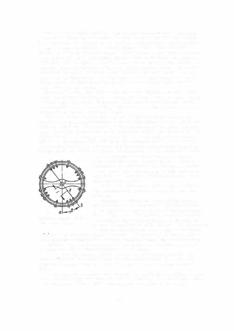
FIGURE 56.  Balance with dis-
placed center of gravity 

clearly  apparent in  this  last cas e .   In o rder  to 

reduce  the  difference between the  two  winding 

extre m e s ,   the  maximum  and  minimum  m om ents 
of  the  spring  are  m ade  as  near  to  one  another as 

pos sible:  the  maximum  difference  between  them 

must  not  exceed  2 5 "/o .  

Pocket-and  wris twatch  springs  are  calculated 

for  a  minimum  of  45  hours  watch ope ration  per 

winding. 

Unbalance  of  the  balance-hairspring  system, 

or displacem ent  of the  center of  gravity  relative 

to  the  axis  of  revolution,  is  one  of the  main factors 
p roducing the  s o - called pos ition  e rror in  watches . 

This  displacement  occurs  in spite  of  the  high  ac­

curacy of manufacture  of  the  balance  and hairspring 

(geom etric  dimension s ) ,   and  in  spite  of the  s tatic 

p01smg.  The  displaced c enter of gravity 

(Figure  5 6 )   causes  an addi­

tional  m om ent  during balance  rotation  which  influences  the  watch  in a  man­
ner which  depends  on its pos ition.  A  rule  exists  for the  determination  of 
the  pos ition of the  center  of  gravity  of the  balance: 

1 .   If,  when  the  balance passes  through  its equilibrium  position,  its 

center  of  gravity is  situated below the  axis  of  revolution,  the  watch  will 
advance  at an  amplitude  of  1 4 0  to  1 7 0° ,   and  lag  at  an amplitude  of  2 8 0  to 

3 2 0° .  

2 .   If,  when  the  balance  passes  thrr ugh  its  e quilibrium  pos ition,  its  cen­

ter  of gravity  is  s ituated  above  the  axis  of  revolution,  the  watch  will  advance 
at an  amplitude  of 2 8 0  to  3 2 0°,  and lag at  an  amplitude  of  1 4 0  to  1 7 0° .  

4 1 3  

If  the  center  of  gravity  is  situated  on  the  ho rizontal  diam eter,  the  watch 

will  not have  a  pos ition error,  as  can be  seen  from  the  formula 

(J)  = -

43 200 · 

· COS

· 

(If>), 

where 

(J)  = 

daily  (24 -hour )  watch  e rror; 

balance  weight; 

( 7 )  

distance  between  the  c ente r  o f  revolution o f  the  balance  and  its 
cente r  of  gravity 

q; 

moment  of  hairspring when  it  is  wound  one  radian; 

� 

angle  betwe en  a  vertical line  passing through  the  balance  c enter 
and the ray passing through  the balance  c ente r  and  its  center of 

gravity; 

(<1>) 

an alternating  slowly  convergent  series  arranged  according to 
increasing  values  of  the  amplitude . 

The  function 

(<1>) 

is  shown  in  Figure  5 7 .   The  daily  e rror  will b e  zero 

in the  following three  cas e s :  

1 .   for 

� 

90°; 

COS 

� 

= 0; 

(J) 

= 0; 

2 .

for l = 0 

w = O; 

3 .   for 

<1> = 220°;  S {<t>) 

= 0;  (1) = 0. 

The  daily  e rro r  will  be  smaller,  the  s maller the  balance  weight  and  the 

higher  the  hairspring moment .  It  is  s e en  from  Figure  5 7  that  small  devia­
tions  of the  amplitude  value  from the value  at point 

<1> 

2 2 0°  cause large 

changes  in the function 

(<1>) 

and  the refo re  in the  daily  erro r .   It i s  the re­

fore more  exp e dient to  ope rate  in the  amplitude  range from  3 0 5  to  3 2 0° ,  

since  a  variation i n  the  amplitude  over  this  range  has  alm ost no influence 
on the  value  of 

S (<1>) 

,  and  therefore  on  the  daily  erro r .  

li-0  80 

120 

1oo  200  2w  280  JZO  Joo· 

----

¢ 

FIGURE 57.  The function 

(<%>). 

The  unbalance  of the  balance  wheel  is  inspected in the  following watch 

positions :  c rown  up ,  crown  right,  c rown  down,  crown left.  The  influence 
of the  escapement unbalance  and  clearance fluctuations  on the  watch  e rror 

4 1 4  

is  s imultaneously inspected in  each  of  these positions .  The  adjustm ent 
technique  in the  pos itions  indicated  is  as  follows :  the balance  screws  are 
arbitrarily  numbered  as  shown in  Figure  5 9 ,   the  numbering beginning from 

the  s c rew oppos ite  the hairspring stud  in  the  equilib rium  pos ition  of the 

balanc e .   The  spring is  wound  1  to  1 . 5  turns,  and 
an  amplitude  of  1 4 0  to  1 7 0°  is  s e t .   Time  indica ­
tions  from  the  P- 1 2   instrument in  each  of  the  pos i ­
tions  are  recorded and  the  position  of the  c ente r 

of  gravity,  or  the  heavy  balance  sector,  is  found 

from the  reco rding.  The  balance  wheel  is  pois e d  

b y  reducing the  weight  o f  the  screw in  the  heavy 

zone  or  increas ing the  weight  of  the  opposite  s c rew. 
This  is  done by  placing,  or  removing,  adjusting 

washers  located under the  s c rew heads .  Dim en-

sions for the wa shers us ed in "Zvezda " and "Pobeda" 

FIGURE  58.  Balance-adjusting 

balances  are  given  in  Figure  5 8 .   Washers  of  var -

washers 

ious thickness are available .  Two was hers 0 . 0 1  mm 

thick will  make  the  watch  advance  (or lag) 2 0   sec 

in  2 4   hours;  0 . 02 m m   and  0 . 0 3  m m   thick  washers  will  p roduce  40  and 

60  sec  effects  respectively,  etc . 

Example  of the  adjustment  of a  " Pobeda"  watch. 

The following  daily  errors were  recorded in tests on  a P-12  instrument : 

1. 

At  small  amplitudes ( 140 - 1 70.) : 

Dial  up  -20 sec,  advance ; 
Dial down  -26  sec,  advance ; 

Crmvn  up  - 60  sec,  advance ; 

Crown right  - 80  sec,  advance; 
Crown down + 40 sec,  lag; 

Crown left  + 60 sec,  lag. 

2.  At large amplitudes (280- 320°) :  

Dial  up  -35 sec,  advance ; 
Crown up + 30 sec,  lag .  

T h e  difference  between the errors i n  the two horizontal positions (small  amplitudes) is : 

- 26  - ( 

- 20) 

-

6  sec ( advance). 

The  average  error  in the two horizontal positions  is : 

- 20  +  ( -26) 

-

23 sec (advance). 

The  average error in the four vertical positions (small  amplitudes)  is: 

( -60) 

40 

60 

=  -

1 0  sec ( advance). 

Using a  special table  we find  that the  weight  of screw  No.  4  should be reduced. 

Since the  average error  is negative in the two positions,  the watch will advance.  This should be  taken 

into  account  when re-poising the balance.  If we  reduce the  weight  of the screw  in the heavy sector,  we  also 
reduce  the  moment of inertia of the  balance,  and the re-poised watch will advance  even  more.  In  such 
cases the inverse  procedure  is used,  of adding to the weight of the opposite  screw ;  this will both poise the 

system and improve its oscillation rate.  As  a rule,  the  displaced center of gravity  does not coincide  with the 

position of any  of the  screws  and it  is  usually  necessary  to reduce  or  increase the  weight  of t\vo  adjacent screws. 

The  c enter  of  gravity  of the  balance  is  most conveniently  dete rmined by 

means  of  a  differential  instrum ent .  A  nomo graph  cons isting of  coordinate 
axe s ,   a  number of concentric  circles ,  and a  diagram  of the  balance  and 
s c rews  of  "Pobeda"  watches ,   is  trac ed on the  instrument  scale  (Figure  5 9 ) . 
The  origin of the  coordinates  is  located at  the  balance  cente r,  and  the  axes 
are  directed  along the  lines  connecting  sc rews  1  and  9,  and  5  and  1 3 .   This 
selection  of the  axes  corresponds  to  an  equilibrium  position  of the  balance 
with the  c rown  up .  Points  of  inte rsection  of  the  axes with the  conc entric 

4 1 5 

circles  are  marked  in  seconds  and  in  mm  (adjusting-washer  thickne s s ) .  
Two  "mobile "  coordinate  axes  (m etal  wire s )  are  m ounted i n  front o f  the 
scal e .  

The  instrument panel  ha s  four  knobs ,  located i n  two  pairs  and provided 

with  scales  with 

24  divisions  each,  numbered  0 - 2 0 - 4 0 - 6 0 - 8 0 - 1 00- 1 2 0  sec 

to  the  left  and to  the right.  A  diagram  of  the  watch  in  the  appropriate  test 

position in the 

P- 1 2  instrument  appears below each scal e .  

Balance,  view from the cock side 

FIGURE 

59. 

Instrument for the determination of the magnitude  and direction of displacement of the center 

of gravity of the balance-hairspring system 

The  right- hand  knobs  are  kinematically connected  with  the  horizontal 

m obile  coordinate  axis  and  the  left- hand  knobs  are  connected with  the  ver­
tical  axi s .   Rotation  of  a  knob  b y  a  definite  number  of  s e c onds  o n  its  s cale 
produce s  a  displacement  of  the  co rresponding mobile  axis  on the  nomograph 
by  the  same  number  of  seconds .   Each  knob  displaces  the  axis  it  is  asso­

ciated  with  independently  of the  other.  Daily  errors  of up to 

2  min  can be 

marked  in  each  of the four pos itions  on the  nomo graph. 

The  cente r  of gravity of the  balance  is  determined as  follows : 

1 .   The  differenc e  between  the  daily  errors  in  two  opposite  directions 

(for  instanc e ,   c rown  up  and  crown  down )  is  determined  in the 

P- 1 2  instru­

m ent  at an  amplitude  of 

1 4 0  to  1 7 0° .  

4 1 6  


Content   ..  102  103  104  105   ..