Technology of watch production - part 102
 

  Index      Books     Technology of watch production (Tarasov) 1964 year


Search            


Content   ..  100  101  102  103   ..


Technology of watch production - part 102


In order to make possible the rotation of the pallet fork from one banking pin to the other in normal 

functioning,  a recess for the passage of the guard pin is made  in the roller safety surface.  The recess is lo­
cated on the same radius 

as 

the impulse  pin.  It might happen that a sudden jolt occurs at the moment the 

guard pin has entered the recess (Figure 47,  c).  Then,  the preventive functions pass to one  of the fork horns, 
which will engage the impulse pin and prevent the escape-wheel tooth from passing to the pallet-impulse face. 
The clearance between the horns and the impulse pin must therefore 

be 

smaller than the locking angle. 

This clearance,  however,  must be larger than the clearance between the guard pin and the safety roller. 

This is specified in order to enable the impulse pin to pass freely past the horn and enter the fork notch when 
the guard pin contacts the roller safety surface.  Friction between the guard pin and the double roller,  when 
they come into contact,  must be a minimum,  and the contacting surfaces are therefore finished to a class  10 
or 11 surface finish. 

The  guard  clearances  for  the  guard  pin  and  the  horns  are  thus  fixed  as 

a  function of  the  locking angl e .  

While  setting the  guard  clearanc e s ,   the  as sembler  inspects  the  relative 

positions  of  the  impulse  pin,  the  safety  surface  of  the  double  roller,  the 

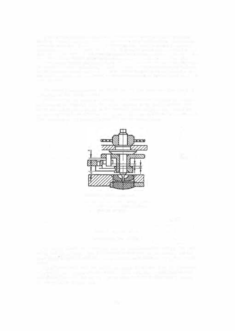
guard pin and  the  fork  horns  in the  vertical plane  (Figure 

48 )

A fter the 

escapement has  been adjusted,  the  balance  is  removed  from  the  m o vement. 
The operation is performed  in parallel  by two assemblers . 

FIGURE 48 .  Vertical clearances: 

a-between fork  and double roller;  b-guard 

pin and impulse pin;  c-horns and impulse 
pin;  d-guard pin and plate. 

S i x t h   o p e r a t i o n  

Lubricating  the  watches 

The  parts  which a re  lubricated a re  the  balance-staff bearings ,  the  train 

axe s ,   and  the  p allets .  The pallet-staff  jewels  are  not lubricate d,  but  the 
staff  itself  is  rubbed with  oil .  Only  well-cleaned  surfaces  should  be lubri­
cated. 

Oil is  introduced into  the watch  m ovement by means  of an  oil dis penser 

(Figure  4 9 ,  a ) .   It is made o f  stainless  steel  with  tips  o f  different  shapes 
and  dimensions  (Figure  49,  b).  Oil  is  stored at the wo rkplaces  in  closed 

oil receptacles  (Figure  5 0 ) .  

4 0 5  

Lubricating  oil  reduc es  and  stabilizes  friction,  reduc es  (and  sometimes 

prevents )  the  wear  of  surfaces  in friction,  and  protects  the  surfaces from 
corrosion. 

No. 1 

No.  2 

FIGURE 

49. 

Tool  for lubricating watch movements : 

a-oil dispenser with base;  b-tips. 

No. 3 

Watches  operate  for s everal  years  without  oil  replacement.  The  oil, 

while  at  first tending to  run,  is yet  mostly  retained  in the bearings .  How­
e ve r,  in the course  of tim e  it  oxidizes,  thickens ,  and collects  mechanical 
and  othe r  kinds  of dus t.  Lubricating  oils  used in watches  must the refore 

have a  high lubricating capacity,  chemical  and 
physical  stability,  and  optimum  vi scosity .  C e rtain 

grades  must  also  have  a  wide  temperature  range 

of applic ation. 

High lubricating capacity  is  necess ary  for the 

reduction of friction,  and thus  of  wear  on the fric ­
tion  surfac es .  Mine ral ,  vegetable  and  animal  oils 
differ in  their  lubricating  capacity .  NIIChA SPROM 

FIGURE 50.  Oil receptacle 

investigations  es tablished  that  the  coefficient  of 

sliding friction  for  a  steel - glass  mating  pair  is 

reduced from  0 . 2 8 ,   for  dry  friction,  to  0 . 2 1  when mine ral - oil lubrication 

is  used,  and to  0 . 1 6  with  bone  oil .  Bone  and  vegetable  oils  are ,  on  the  other 
hand, more  prone  to  oxidation  than  a re  mineral  oil s .   Watch movem ents  are 

lubricated using  compound  oils  made  up  of fractions from  the  vacuum  dis ­

tillation  of mine ral  and  bone  oil s ,   and  synthetic  additives .   Various  grades 
of watch  oil are  manufactured,  and the grade to  be  used in  each  case  is 

4 0 6  

determined  by  the  speed  of  rotation  and  the  contact pressure  of  the  friction 
pairs .  The  grade  is  dete rmined  by the  pe rcentage  ratio  of  the basic  c om ­
ponents  and  additives ,   and  is  characterized  by  the  physicomechanical  prop ­
e rties  listed  in  Table  2 .  

TABLE  2 

Physico mechanical  properties  of watch  oils 

Acidity number, 

Engler  viscosity 

�� 

mg per 

g of oil, 

• 

GOST  33-53 

.S 

� 

Oil grade 

Use 

according  to 

:::l 

0  rl 

o.. E-< 

GOST 

5985-51 , 

at 

5o•c 

at 

2o·c 

!:l  (/.) 

'

;( 

0  0 

"' 

maximum 

n. <.)  

MBP-12 

Balance  and pallet be arings  of wrist-

and pocket-watches 

.

.

.

.

.

.

.

.


0.18 

2 .8- 3.2 

8.4-9.6 

-20 

MZP-6 

Train bearings  of wrist-and  pocket-

watches 

.

.

.

.

.

.

.

.

.

.

.

.

.

.

.

.

.


0.18 

3.

3

-

3

.

1 0.9-11 .9 

-20 

MTs-3 

Barrel subassembly  of 1<rist-and 

pocket-watches  and  alarm-clock 

bearings 

• •  

 0 

 0 


0.18 

3.\}-4.2 

13.3-14.3 

-15 

P

S

-

Alarm-and table-clock springs 

.

.

.

• 

0.40 

4.5-4.9 

-

-

RS-1 

Keyless work subassembly 

.

.

.

.

.

.


0.8 

-

-

-

The  amount  of  oil  used in lubrication must  be  s trictly  controlle d ,   as  an 

unduly large  amount  could  impair  watch  operation.  Thus,  if  oil  drops  are 
pres ent  in the pallet- arbor  jewels ,  an additional  mom ent m ust be  applied 
in  rotating the  pallet lever to  overcom e  the  liquid  friction  in the  oil  laye r. 

S e v e n t h  o p e r a t i o n  

Movement  starting  (preliminary) 

The  ass embler  s ets  the  balance  with  the  hairspring in  the  lubricated 

j ewels  in the cock and  plate,  fastens the hairspring stud,  inspects  the  clear ­
ances  between  the  balance  whe el,  the  hairspring  and  the  parts  lying near 
the m ,   prelim inarily  sets  the  hairs pring  in the plane  and  with  respect  to the 
c ente r,  and  es tablishes  the  clearance  in the  regulator  curb  pins . 

E i g h t h   o p e r a t i o n  

Movement  starting  (final ) 

The  hairs pring is  finally  and  accurately  set in  the  plane  and  on  c ente r. 

Figure  5 1 ,  a  shows  the  m e thod  of s etting the  outer terminal  curve  in the 
plane  by  means  of pincers ,  and  F igure  5 1 ,  b  shows  the  curve  position  after 
the  s etting.  The  plane  of  the  terminal  curve  is  parallel  to  the  lower plane 
of the  balance  cock. 

407 

Incorrect pos itioning of  the  outer te rminal  curve  in  the  horizontal  plane 

upsets  the  shape  of the whole hairspring,  and the turns become irregularly 
disposed ( Figure  5 2 ,   a  and b ) .  

FIGURE 51.  Setting the outer terminal curve of the hairspring 

in 

the plane 

FIGURE 52.  Setting the outer terminal curve of the hairspring  according to center 

The  hairspring is  returned  to  its  normal  shape  by manipulating  the  outer 

terminal  curve ,  using pincers  (Figure  5 2 ,   c ) .  If necessary,  the inner ter­
minal  curve  is  also  modified and the ass embler  then  sets  the final  clear­
ance between the  regulator curb pins . 

The  total  clearance  between the  hairspring and  the  regulator  curb  pins 

(Figure  5 3 )  must be  between  5 0 %  and  1 0 0 %  of  the hairspring thicknes s .   By 
rotating the  regulator  to  its  extreme positions,  the  ass embl e r  checks  the 
clearance  established and  the  correct position  of this  s e ctor  of the  outer 

te rminal  curve;  the  curve  in this  s ector is  then adjusted if nece ssary. 

The  ass embl e r  now  "centers "  the  escapement.  With the  m ainspring 

completely unwound,  the balance  must be  so positioned  that the  impulse  pin 
will  lie  on the line  c onnecting all  c enters  while  being inside  the  fork notch 

(Figure  54 ).  The  pallet fork must be positioned  equidistantly from  the  two 

4 0 8  


Content   ..  100  101  102  103   ..