Technology of watch production - part 101
 

  Index      Books     Technology of watch production (Tarasov) 1964 year


Search            


Content   ..  99  100  101  102   ..


Technology of watch production - part 101


revolutions,  the  better  the  m e sh  or,  in  the  ass emblers '  language,  the 
easier the  " rolling".  The  number  of  reve rs e  rotations  of  the  es cape  wheel 

in  " Zvezda "  wristwatches  must  be  not less  than  4 .  

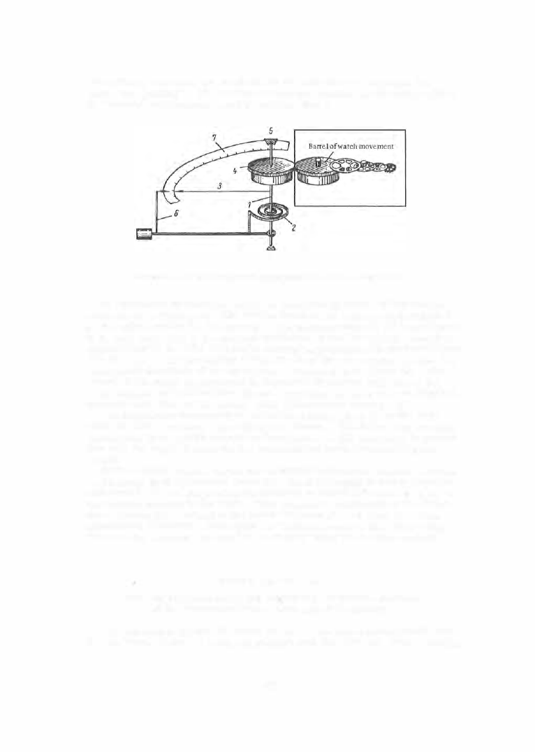
FIGURE 44.  Schematic diagram of the instrument for checking quality of mesh 

In  ce rtain  cases  the  mesh  quality  is  inspe cte d  by m eans  of  the  instru­

ment shown in Figure 

44.  The driving force  of the instrument is  supplied 

by the  spiral  sp ring  (2 )  (hairsprin g ) .   The  instrument  s cale  ( 7 )  is  graduated 

in  g.  m m ,   acco rding to  the  m oment  developed by  the  hairspring,  when  it is 
twis ted  from 

oo  to  1 5 0°.  The  s cale  us ed for wristwatches is  graduated f rom 

0  to  1 5  g. mm .  The  hairspring  (2 )  and  the hand  ( 3 )  are  m ounted  on  axis  ( 1 ) .  
The  second  e xtremity  o f  the  hairspring i s  fas tened t o  the  leve r   (6 ) .   The 

barrel  of the  watch  m o vement  to  be  inspected is  m eshed  with  barrel  (4 )

In  the  abs ence  of  l oad  the  hand  ( 3 )  and  the  pointer  on leve r   (6 )  a re  disposed 

opposite each other  on the  scal e .   A xis 

( 1 )  rotates i n  bearings  (5 ). 

The  instrument hairspring is  loaded by  rotating lever  ( 6 )  to  the  right 

from  its  initial  position .   Hand 

( 3 )  is set at  zero.  The  hairspring moment, 

transm itted  to  the  watch  m ovement through barrel  (4 ),  increases  in  propor­

tion with the angle  of twist till  the  transm ission being inspected be gins  to 

rotate . 

A t  the  instant  rotation begins  the  maximum hairspring  m om ent  is  shown 

on the  s cale  by  the  pointer  of lever  (6 ).  Hand  (3 )  begins  to  rotate  together 

with barrel 

(4 ),  and  stops  when the  moment  on barrel  (4 ) becomes  equal  to 

the friction  mom ent  in  the train .  This  m om ent  i s  calculated  as  the differ­

ence  between  the  readings  of the le ver  indicator  (6 )  and  hand  ( 3 ) .   This 
instrum ent,  the refore ,  dete rmines  the  fric tion  losses  in  the  wheel  train . 
The  starting mom ent  was  found  to  be  roughly  twice  the  friction m o m ent. 

T h i r d   o p e r a t i o n  

Mounting the pallet leve r  and inspecting the  relative position 

of the  escapement-wheel  teeth and of the pallets 

The  assembl er inserts  the  lower  j ournal  of the  pallet  subass embly into 

the  cap  j ewel ,  locks  the  bridge  in  position  with  two  pins  and,  after  inserting 

40 1 

the  upper journal  into  the  bridge  jewel ,  press es  the  bridge  firmly against 

the  plate  and tightens  the  screw.  The axial  clearances  in  the  jewels  are 
inspected using the same  method  as  was used for the  wheels .  Radial  clear­
ances  are  not inspected. 

FiGURE 

45.  "Zvezda'' w atch movement after 

the  third operation 

After the  axial  clearances  have  been inspected and  any possible  s kew 

corrected,  the  ass emble r  checks  the  he ight pos ition  of  each  es cape-wheel 
tooth  on the  receiving and  discharging pallets .  The  locking,  run - to-bankings 
and drop  angles are then  inspected  visually.  To  that  end,  the  spring is  wound 

by  1 !- to  2  turns  of the  winding  c rown,  and  the  pallet  fork  is  displaced from 
one banking pin to  the  other using pince rs ,   until  the  es cape  wheel has  com ­
pleted  one  full  revolution.  If the  es cape  wheel  has  a  large  radial run- out, 

it  can happen  that  the  " run- out"  tooth  on the  escape  wheel  does  not free  the 
pallet  impulse  fac e,  and  the  watch  stops .  C onvers ely,  it  could  happen  that 
the  short escap e - wheel  tooth  has  a  very  small  locking angle  with  the  pallet 
which  does  not ensure  the  action  of the es capem ent  guard  devices  (guard 

pin,  horns ,  and  double  rolle r  with impulse  pin ) .  

A part from  the  axial  clearances,  the  ass embler inspe cts  the  clearance 

between the  tooth heel  and the pallet back fac e .   The  value  of  this  clearance 
for the  dis charging pallet  (Figure  4 6 )  is  1 ° 3 9 ' 3 0 " (drop  angle )  or  0 . 0 7 7  m m .  

This  operation takes  twice  the  time  required  for the  previous  operation, 

and  it is  the refore  performed by  two  ass emblers  in parallel  at the  same 
tim e .   Figure  4 5  shows  a  " Zvezda "  watch  movement  after the  third  ass embly 
operation. 

F o u r t h   O p e r a t i o n  

Mounting  the  lower balance  endstone  cap  and  the  bal

a

nc

This  operation is  preparatory to  the  fifth  opera tion.  The  plate  is  rotated 

to  a  dial - side - up  pos ition  and  the  place  where the cap is to be fitted is cleaned 

by an  air  jet.  The  cap  with  the jewel  is  m ounted,  and the plate is  returned 
to  its  form e r  position.  The balance  and  hairspring ass embly  is  then set on 
the plate,  the j ournal  is  carefully  introduced into the  lower balance  end­
s tone  cap  j e wel  and  is  covered by  the balance  cock  on which the  regulator, 

402 

the upper cap and the  stud  s c rew have already been mounted.  The  ass embler 
adjusts  the axial  clearance  between the balance  journals  and the  jewel s  by 
introducing washers  between plate  and  cock,  or by bending the cock s o m e ­
what,  t o  which  e n d  it i s  p rovided  with  a  special  rec es s .  

F i f t h   o p e r a t i o n  

Establishing  guard  clearances  between  the  pallet  fork  and  the  double 

roller.  Removing  the  balance  from  the  movement 

In  order to  establish  the  neces sary  clearance between the  es capement 

guard  pin and the  double - roller safety surface,  the  ass embler winds the 
spring  until  the  fork  contacts  one  of  the banking pins .  Then.  using pinc e rs ,  

h e   d raws  the  fork  away  from  the  banking  pin  until  the  guard  pin  comes 
into  contact  with  the rolle r  safety  surface.  The  magnitude  of the clearance 
is  dete rmined from the magnitude  of  the  fork  (pall e t )  deflection from  the 
banking pin .  The  fork  is  then displaced  to  the  s e cond banking pin,  and  the 
procedure  is  repeated .  

FIGURE 46.  Position of the escape-wheel tooth and 
the receiving pallet during locking 

4 0 3  

If  the  clearance  is  too large  or  too  small,  the  pallet lever is  removed 

from  the  m ovement  and the  gua rd pin is  s ho rtened  or drawn out.  A fter the 

required clearances  have  been set,  the  assembler inspects  the  clearances 

between the horns  and the impulse  pin. 

The  operation of the  escapement will now  be described briefly  in order to make  clear the  question of the 

clearances.  The  lever escapement (as  do  all  other  escapements)  performs  two functions :  it  periodically 

transmits impulses to the balance  in order to sustain its  oscillations,  and it  periodically  unlocks the wheel 

train for rotation,  as can be  seen from the intermittent  motion of the seconds hand .  The seconds hand  is at 
rest for roughly 

0,95 

sec,  and in motion for the remaining 

0.05 

sec.  Escapements must be designed so that 

their functioning is  not disturbed by  sudden  external  jolts,  and they  are  therefore  provided with special guard 
devices. 

The lever escapement  of " Pobeda"  1�atches is shown in Figure 

46. 

When the escape-wheel tooth 

is 

on the  receiving-pallet  locking  face,  the  fork  contacts the  left-hand 

banking pin and the balance  moves in a  free  oscillation to the left  of the equilibrium position.  If the escape­
ment functions properly,  that  is if there are no sudden jolts,  the balance will introduce the impulse pin into 
the  fork notch when  it  returns  to its equilibrium position.  On  overshooting the  equilibrium position,  the  im­
pulse pin knocks the fork 

3' 

to the  right (locking  angle).  The  escape-wheel tooth passes from the  locking 

face  of the  receiving pallet to  its  impulse face  and rotates the  pallet  lever by  the  impulse  angle  of 

7'40' 

( 5'40' 

pallet  angle + 

2' 

tooth angle).  The fork  notch in turn transmits the impulse  to the balance,  which 

moves  in  a free  oscillation to the right of the equilibrium  position.  Under the  action  of the  drawing force  on 

the discharging pallet,  the pallet  lever travels an  additional angle 

( 0'50'), 

called the run·to·bankings  angle, 

and  reaches the right-hand banking pin. 

Assume  that the escapement has a short  guard pin and that the fork under the influence of a sudden jolt 

has receded from the left  banking pin so that the escape-wheel tooth has passed  from the locking face to the 
impulse  face  of the  receiving pallet.  The  moment transmitted by  this  tooth  will then  rotate the  pallet fork 
through 

8'30' ( 5'40' 

2' 

50') 

until  it  engages the right-hand banking pin.  The balance,  on returning  to 

the  equilibrium position,  will no longer  be  able  to introduce the  impulse pin  into  the fork  notch.  The pin 
will instead strike the outer surface of the fork horn  and the balance  will stop (Figure 

47, 

a). 

FIGURE 

47. 

Action of the  guard  devices: 

a-premature throw  of the  pallet-lever fork,  guard pin being short;  b-guard pin engages the 

roller (safety  surface) preventing fork  rotation;  c-horn engages the  impulse  pin. 

A blow of this nature usually breaks the impulse pin.  In order to prevent watch stoppage  and the  acci­

dental passage  of the pallet fork from one position into the other,  a  guard pin of suitable  length  is  mounted 

in the fork,  and the balance  double  roller has  a cylindrical guard  surface with  a  recess.  When a sudden jolt 
occurs,  the fork leaves the  banking pin but the guard pin touches the  safety surface  and prevents the escape­
wheel tooth from slipping onto the impulse face (Figure 

47, 

b).  A  clearance  is specified between the guard 

pin and the safety surface in order to avoid unnecessary friction during normal functioning  of the escapement. 
The  angular  value  of this clearance  must be smaller  than the locking angle.  The clearance  is usually  between 

0,03 

and 

0.05 

mm (see Figure 

46). 

404 


Content   ..  99  100  101  102   ..