Technology of watch production - part 107
the es cap ement, the whe el train, and the barrel and mainspring. E xamples
could be cited to illustrate other ass embly defects encountered, such as the
s e c onds hand brushing the dial, defective j ewel s , etc .
I t was earlier mentioned that
the m easurement of the oscillation rate for
the balance
-
hairspring system is accomplished on the P- 1 2 watch- tim er
with the aid of a spec ial head (see Figure 6 9 ) provided with a standard watch
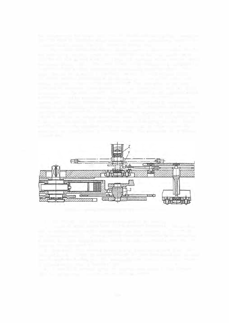
m ovement (Figure
68 ).
The lower j ournal of the balance to be adjusted ( 1 )
is set in a fixed bearing consisting of two suitably m ounted rubies . The
upper j ournal is supported in the hinged bearing (2 ) with similar rubie s .
T o ensure correct pos itioning o f the impul s e pin i n the pall e t - l e ve r fork
notch, especially afte r the hairsp ring length has been altered, the table
carrying the standard watch m ovement can be rotate d about axis (3
)
, which
is coaxial with the balance s taff . The head is provided with a piezoelectric
mic rophone , and its ope ration is basically similar to that of the normal
instrument, the only difference being that the head body is additionally
equipped with chucking and cutting devices for the hai rspring and stud and
can therefore perform the following op e rations : adjustment of the hairspring'
l ength to achieve the proper oscillation rat e , pinning of the hai rspring end
in the stud, and cutting the superfluous ends of hairspring and pin. Rubber
padding between the standard watch m ovement and the table reduces the
abs o rption of sound puls es by the head mas s . The proc edure is as follows
(Figure
6
8 ):
FIGURE 68 . Standard watch movement of the P-12 watch-timer head
1 .
The balance with hairsp ring is mounted in the bearings .
2 . Lever
( 6 ) which opens jaws ( 1 2 ) is pressed downward. The stud is
set, oriented relative to the hairspring, and then clamped in the j aws by
the release of lever
(6 ) . Lever ( 6 ) is then displaced late rally in the direction
of arrow m . This displaces jaws
( 1 2 )
to its extreme working pos ition, ad
jus table through scre w ( 9 ) .
3 . E c c entric ( 7 ) is rotated t o pos ition C , thus opening j aws ( 1 2 ) . The
hairspring end is drawn by pince rs through the jaws introduc ed into the stud
hole through the fee ding jaws ( 5 ), and finally into the slot in pin (4 ), whe re
it is fas tened by rotating the wheel (3 ) .
4 . Lever
(6 ) i s pressed again, freeing the stud which i s then aligned
with the hairspring. The stud is then clamped again .
4
2
5