Technology of watch production - part 98
 

  Index      Books     Technology of watch production (Tarasov) 1964 year


Search            


Content   ..  96  97  98  99   ..


Technology of watch production - part 98


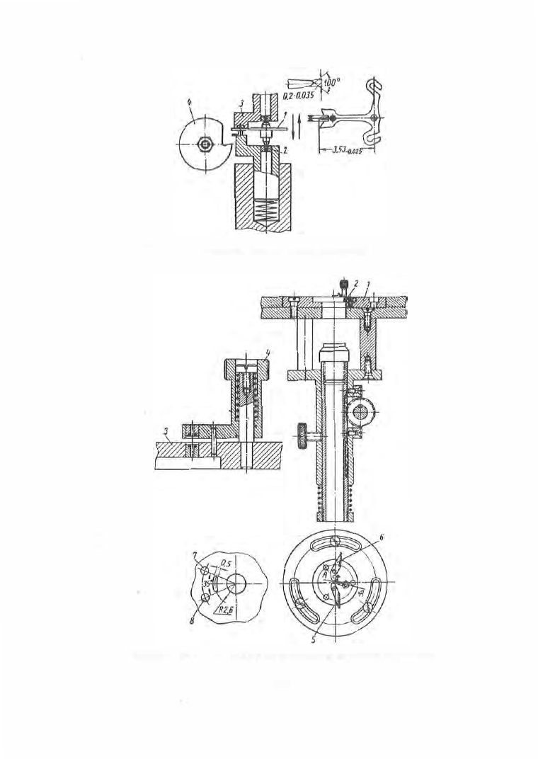
FIGURE  29.  Fixture  for  pointing  guard-pin end 

FIGURE 30.  Attachment on profile projector for mounting the  pallets in the  pallet  lever 

3 R!=l 

A s sembly begins  with  the  pressing-in  and  the  riveting of the  guard  pin  in 

the pallet lever,  using a  hand  press  or the  pedal - operated D-246 press 

(Figure  2 8 ) .  

The  guard pin i s  then  set manually,  by means  of pincers ,  both  with 

respect to  paralelleity  to  the  lever  plane  and  relative  to the  center  line  of 

the  fork slot.  The  guard-pin  extremity  must  not deviate  from  the  center 
line  of the  slot by more than ± 0 . 0 3  mm .  The  reliability of  the  guard -pin 
mounting is  checked  by random sampling in a  special inspection devic e .  

Next,  staff  ( 1 )  i s  pressed into  pallet lever ( 2 )  o n  a hand press  o r  on the 

pedal - operated D - 2 4 6  press .  The  reliability  of the  mounting is  inspected 

(5 "/o 

sample )  in a  special  devic e .  

The  guard -pin  tip  is then pointed  using a  bench- type  hand  press  and  a 

special  fixture  (Figure  2 9  ) .   The  pallet lever  ( 1 )  i s  located b y  its  staff 

journals  in the  steel  bearings  (2 ),  and  clamped between the  plunger  ( 3 )  and 

its  spring-loaded counterpart .  A  profiled circular cutter  (4),  ground  to  the 

desired shape  of  the  guard - pin  tip,  is  also  mounted  on  the  press .  When the 

plunger,  together  with  the  pallet,  is  lowered,  the  cutter planes  or s haves 
the pin tip . 

Guard - pin pointing  is  followed by the  preliminary  setting  (in  the  device ) 

of the  pallets  in  the  pallet-lever slots .  Their  exact setting i s  performed 

in  a profile projector,  on whose table  ( 1 )  the  attachment  (2 )  is  mounted 

(Figure  3 0 ) .  

The  attachment  consis ts  o f  a  lower plate  ( 3 ),  an  upper clamp  ( 4 ) ,   levers 

( 5 )  

and  ( 6 ),  and  setting pins  ( 7 )  and  ( 8 ) .   A  drawing of  the  pallet lever  and 

banking pins  on tracing paper  or glass  is  fastened to  the  projector s creen. 

The  pallet lever is  mounted in the  jewel bearings  of the  lower plate  ( 3 )  and 

the  upper  clamp  (4),  and is pressed by pincers  against one  of the banking 

pins .  The  pallet position  is  projected on  the  screen through  the  central  hole 

of the plate and  compared with the drawing,  on  which the limits  of  the pallet 

position are  marked out.  The pallet is  displaced along its slot by levers ( 5 )  

and  ( 6  ).   This  method o f  positioning and inspecting the pallets  is  very ac­

curate and quick.  The  pallets are now fixed in position in their slots  by 

molten  shellac  which  flows  into  the  free space  in the  slots ,  the  lever being 

heated to  7 0 - 8 0°C  on a  special  brass plate. 

A s sembly of  the  Balance 

The balance  subass embly includes  the  balance  wheel with screws ,  the 

balance staff,  and the  double  roller with impulse pin  (Figure  3 1 ) .  The bal ­

ance  subassembly must be  poised,  its  s c rews  must be  tightly  screwed into 

the  wheel,  and  the  double  roller and  wheel  must  be  reliably fastened to  the 

staff .  The  assembly operations  are  as  follows :  mounting  the  screws  on 

the  balance  wheel  using adjusting washers  under the  four compensating 

sc rews  (Figure  3 2 ,   a ),  mounting  the  balance  wheel  on  the  staff  and  stak­

ing  (Figure  32, b ),  s etting the  balance  wheel  in the  face plane  (Figure  3 2 ,  c ), 

mounting  the  double  roller  on  the  staff  (Figure  32,  d ),  and  static  poising 

(balancing) of the subassembly  (Figure  32, e ). 

A  mechanical  s crewdriver  is  used in  certain wateh plants  for mounting 

the  screws  on the  balance  wheel .  Its  use  much  simplifies  the  performance 

3 9 0  

of  this  complex  ope ration,  and  inc reases  the  production rate  for  the  oper ­
ation b y  about  5 0  

o/o . 

The  mechanical  sc rewdriver  consists  of  the  sc rewdriver  proper,  a 

DT- 7 5  electric  m oto r 

( n  

2 8 0 0  rpm )  with  a  flexible  shaft,  and  an  RVN - 2 0  

vacuum  pump  with  a  com m on  air  duct for  1 5  

to  2 0  me chanical  sc rewdrivers  (Figure 

3 3 ) .  

A n  aluminum  body  encloses  the sc rewdriver 

me chanism  and  the total weight is  less  than 

1 5 0  g.  The  body  is  eas ily  dismantled  for  clean ­

ing.  The  sc rewdriver  guide  shaft 

( 1 )  

is  con­

nected  at  one  end  to  the  flexible  shaft  at the 

electric m otor,  and at the other end to the collet 

holder 

( 3 )  and  collet  ( 4 )  through the friction 

coupling  (2 ).  When operation  is  to  be gin,  the 
m otor  and  pump  are  s witched  on,  the  screw­
driver  is  gripped by the right hand  s o  that  the 

thumb  is  on  the  trigger  ( 5 )  and the  balance  is 

FIGURE 31. 

Balance 

subassembly 

held  on  the  table  by  the  left hand.  The  collet 
nose  is  b rought near the head  of  one  of the 

screws ,  which  are  spread  on an  inclined  table ,  

and  the  collet i s  opened b y  p ressing o n  the  trigger .   The  s c rew head is 
sucked into the  collet housing and the  trigger  is  then  released.  The  s c rew­
driver  collet  nose and the  s c rew  rotating with the collet are brought  opposite 
one  of the  holes  in the  wheel  and the  s c rew is  s c rewed  in it .  Pressure  on 

the trigger opens the  coll et and the  s crewdriver  is  withdrawn.  The  entire 

operation  takes  a  fraction  of a  second . 

i--oo2----l 1 

0.02 

FIGURE 

32. 

Balance assembly : 

a-mounting the screws;  b-mounting the balance  wheel  on the staff;  c-setting the  balance  wheel  in the 
face plane;  d-mounting the  double  roller on the staff;  e-staric poising. 

3 9 1  

Valve  ( 6 )  has  been p rovided for cases  whe re defective  s c rews  (with a 

tight  thread  or  none  at  all )  a re  in  the  collet,  and  have  to  be  remove d .   The 

spindle  nose  is  inserted into  the  valve  cone 

( 7 )  and pressure  on the  valve 

b rings  it  oppos ite  the  hole  in  tube  (8 ) .   The  vacuum  i n  the  tube  sucks  the 
s c rew out  of the  c ollet housing  (the  c ollet being open )  and it falls  into  the 

valve  pocke t .   Spring  ( 9 )  then  returns  the  valve  to  its  initial position. 

FIGURE 33.  Mechanical screwdriver for  mounting screws on 
balance wheels 

A n  automatic  machine  for m ounting  sc rews  on  the  balance  wheel  of 

"Zvezda"  watches  is  in  us e  at  the  Penza  watch  plant  (Figures  34  and  3 5 ) .  

A  turret head o n  this  m achine  has  1 0  balance  housings  i n  which  the  bal ­

ances  are  held  by  springs .  The  turret head  is  imparted  a  reciprocated 
motion in a  longitudinal  direction by  a  cam .  It  is  indexed  3 6 °  each  tim e  it 

is  withdrawn,  so  that  one  s c rew is  m ounted  in each  of  the  1 0  balances . 

A fter  one  complete  revolution  of  the  turret head,  the  shafts  on  which  the 

b3.lanc e  wheels  are  m ounted  are  indexed  by an  angle  which  depends  on  the 
balance  design .   In the  case  of the  "Zve zda" balances ,  which  have  1 2   sc rews 

re gularly  distributed  on  the  wheel  circumferenc e ,   the  indexing angle  is  3 0 ° .  

A l l  the  balanc es a r e  indexed by the  s a m e  angle  and  the  m ounting  cycle  i s  

repeat e d .   The  machine  stops automatically after all  the  s c rews  have  been 
m ounted. 

392 


Content   ..  96  97  98  99   ..