Technology of watch production - part 96
 

  Index      Books     Technology of watch production (Tarasov) 1964 year


Search            


Content   ..  94  95  96  97   ..


Technology of watch production - part 96


Narrow fitting tolerances are imposed on  the  parts  in order to  ensure 

the reliable  setting of the toothed wheels  on the pinions  and mimimum  radial 

and face run -out .  The  central hole  of the  wheels  is  die -shaved with  a  toler­

ance  of  0 . 0 05 mm on the diameter  and  0 . 005 to  0 . 0 1  mm run -out  relative  to 

the  wheel  circumference .  

Pinions  are machined  on Swis s - type  automatic  screw machines  with a 

fitting- diameter tolerance  of  0 . 005  to  0 . 0 1 0 mm .  

The  assembly o f  the  wheel  and pinion  consists  in  fitting the  wheel  on the 

pinion,  staking,  alignment  of the  wheel in the  face plane ,  checking the  as ­
sembly tightness and  the radial  and  face  run -out . 

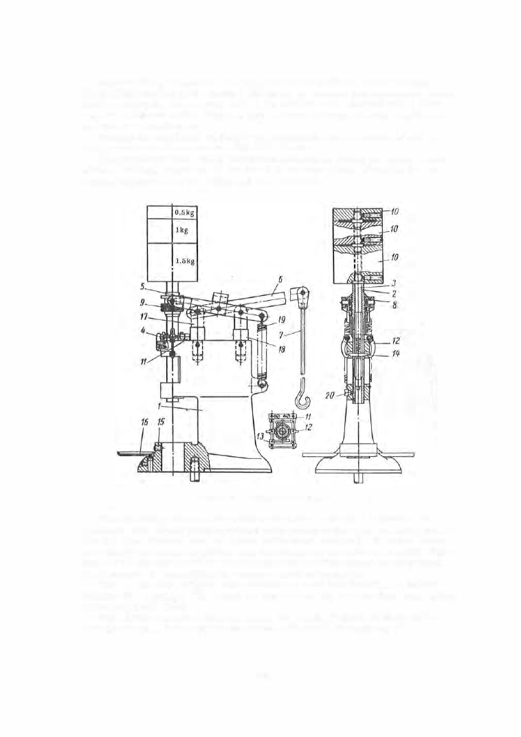
FIGURE  16.  D-246  pedal-operated press 

Wheel s  are pressed on the  pinions  using  hand - or pedal -operated table 

presses .  The  D - 2 4 6  pedal- operated table press  is  the  most versatile press 
for this  type  of work,  and its  design  is the most advanced.  It is  used both 

for fitting the  wheels  on pinions  and for fitting the  balance  on its  s taff.  Stak­

ing can be carried out in the  same  operation and this arrangement  is  used, 

for example,  in assembling the center-wheel  subassembly. 

The  D-246 press  (Figure  1 6 )  comprises  a  cast- iron body  ( 1 ),  a  hollow 

spindle  ( 2 ),  a  plunger  ( 3 ),  a  fork  ( 5 )  and a  lever  ( 6 ),  the  last  two  being linked 

by an adjustable j oint. 

Fork ( 5 )  is  connected  through  stones  ( 8 )  to nut ( 9 )  which is  screwed  on 

the  spindle  (2 ).  Lever  (6 ) is  connected to the  pedal  through  rod  ( 7 ) .  

3 8 1  

Weights  ( 1 0 )  a re  mounted  on  the  upper  end  of  plunger  ( 3 ) .   B racket  ( 1 1 ), 

mounted  on  the  upper  face  of  the  body  ( 1  ),  and plate (4 ),  fastened to the 

front  of the  body,  carry  two  rods  which  in  turn  mount  the  pawls  ( 1 2 )  

and  the  levers  ( 1 3 ). 

Plunger  ( 3 ),  togethe r  with  weights  ( 1 0),  is  held in  the  upper position by 

pin  ( 1 4 )  which  is  s upported on the pawls  ( 1 2 ) .  

An  exchangeable  die  is  inserted  in  a  hole  in  the  lowe r   part  o f   the 

body,  and  is  fastened in place  by  sc rew ( 1 5 ).  Three  trays  ( 1 6 )   which 

hold the  two  parts  and  the  ass embled subassembly,  are  fastened to  the 

lower part  of the  body.  Fork  (5 )  and lever  ( 6 )  are  mounted  on supports ( 1 7 )  
and  ( 1 8 ) .   Spring  ( 1 9 )  holds  the  spindle  (2 )  in the  upper position.  Pressing 

and  staking punches  are  fastened in the lower part  of the hollow spindle and 

the  plunger,  respectively. 

The pinion  (or  s taff)  is  placed on the  die  using pincers and the  wheel  to 

be mounted is placed on it.  When the  pedal  is  pressed,  fork  ( 5 )  lowers 

s pindle  (2 ),  and the  spindle  punch presses the wheel 

onto  the  pinion.  Simultaneously,  the lower face  of 

nut  ( 9 )  engages  the  pins  on the levers  ( 1 3 ),  and these 

56 

cause  the  pawls  ( 1 2 )  to  release  pin  ( 1 4 ).  Plunger  ( 3 )  

falls ,  under the action o f  weight ( 1  0 ) ,  strikes punch ( 6 )  

(see Figure  1 7 )  and  stakes  the  assembly.  The  im­

pact is adjusted by changing the  weights .  The  spindle 

FIGURE  17 .  W orking parts 
of the  die: 

1 -body ;  2-guide ;  3-stop; 
4-die plate ;  5 -pressing 
punch;  6-staking  punch. 

travel  is  adjusted by nut  (9 ),  and  its lift is  limited 

by  screw ( 2 0 ) .   The  production rate  is  4 0 00  sub­
assemblies  per  shift. 

Figure  1 7  shows  the  punches and die  for  fitting 

and  s taking the  center  wheel  of  "Pobeda" wrist­

watches . 

If  the  fitting diameter  of  the  pinion  or  staff  is  very 

s mall ,   the  wheel  is  first  firmly m ounted on a  hub 

(Figure  1 8  ),  and  the  hub bed wheel  is  then  m ounted 

on the  staff  or pinion.  After  the  wheel has  been  fitted 

on  the  pinion,  it  is  aligned  in the  face plane  on the 
P- 32 instrument  (Figure  1 9 ) .   The  wheel  ( 1 )  t o  be 
inspected is  clamped between the  c enters  ( 2 ),  and 

is  rotated by a  d rive r .   Face  run- out is noted on the 

s cale  of the built-in  dial  gage  ( 3  ).  The wheel is 

aligned by hammer ( 4 ) .   The dial  gage  and hammer 

are s et near the  wheel  rim . 

The  d river together with  the  pulley  is  driven by 

the  electric  m otor  through  a  belt transmission. 

Wheels  and  balances  with  diameters  between  4  and 

1 5  mm  can be aligned  on the  P- 32  instrument .  The  dial - gage  scale has 

divisions  of  0 . 0 1  mm .  The  wheel  revolves  at  1 2 0  rpm  and  the  electric  motor 

at  1 5 00  rpm .  The  production rate is  1 5 00 s ubass emblies  per shift. 

Radial run- out  wheels  is  inspected using  either a  comparator  or a  spe­

cial  dial  gage  (Figure  2 0 ). 

The  instrument  consists  of  a  bed  ( 1 ),  a  gear pair  ( 2 )  with  handle  ( 3 ) ,   a 

driver disk  (4),  a  pair of fixed  centers  ( 5 ),  and  a  dial  gage  ( 6 )  mounted in 

an  adjustable  b racket  ( 7  )

Parts  and  subassemblies  are  inspected between 

male  or female  centers .  Small  parts  are  rotated  manually. 

3 8 2  

Each escape- wheel  subassembly  is  inspected for external  diameter  run­

out  and pitch accuracy,  simultaneously,  on a profile  projector at a  magnifi­

cation of  l O OX,  with the  aid of the  attachment  shown  in Figure  2 1 .   The 
escape- wheel  subassembly  ( 1 )  is  placed in  the  standard  watch  movement (2 ), 

using  pincers .  The  upper  jewel  is mounted in a  movable  clamp  (3) which 

fits  into  a  special  cutout  made  in the  standard  movement. 

FIGURE 18. 

Wheel-hub  >Ubassembly 

FIGURE 19.  P�32 

instrument for  aligning  and for  checking  the  face  run-out  on  sub­

assembled wheels and  balances 

3 8 3  

FIGURE 20.  Instrument  for radial-run-out  inspection of wheels 

FIGURE 21.  Profile-projector  attachment for measuring radial run-out and pitch 

accuracy of escape wheels 

TABLE  2 

Wheel-assembly testing moments 

Subassembly 

Center wheel . 

Third wheel  . 

Fourth wheel 

. . . . • . . . . . . . . . • . •  

Escape wheel 

. . . . • . • . . .  ,  • . . • • •  

Testing moments 
for K-26 w atches, 

g. mm 

1650 

470 

390 
150 

3 84 

Testing  moments 

for K-36 watches, 

g. mm 

2500 

800 
800 
600 


Content   ..  94  95  96  97   ..