Technology of watch production - part 97
The subass embly is loaded and unloaded by lifting the clamp ( 3 )
,
thus
compressing spring (4 ). The attachment is mounted on the projector table
in such a way that the position of the wheel tooth on one of the pallets of the
standard- m ovement pallet lever is shown on the screen.
A s caled drawing on tracing paper or glass , with lines which indicate
the permissible limits of the wheel-tooth radius and impulse - face length,
is placed on the s c reen.
Tightness of the assembly of wheels on pinions is checked by random
inspection on the device described below. The pinion is clamped in the
collet of the device used, and a moment - creating weight is suspended from
the wheel (see Table 2 ). The assembly is considered satisfactory if the
wheel on the pinion does not slip under the weight.
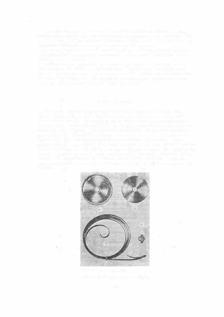
Barrel Ass embly
The barrel assembly consists of the barrel body itself (Figure 2 2 , a ),
the cap (Figure 2 2 , b ) the arbor (Figure 2 2 , c ), and the mainspring with
b race (Figure 2 2 , d ) . The m ainspring i s supplied t o the watch plant i n a
finished state . The radial and face run- out of the ass embled barrel must lie
within specified limits . The maximum permissible radial run- out for the
gear rim of the "Pobeda " wristwatch barrel is 0 . 0 1 5 m m . The m aximum
permissible face run- out on the rim circumference is 0 . 02 mm . These re
quirem ents are very strict, if we take into account that the tightened spring
causes the arbor to m ake full use of any radial clearance of the arbor in the
barrel. In order to satisfy such requirements , the radial clearance of the
arbor in the barrel must not be more than 0 . 005 to 0 . 0 1 0 mm, which is
achieved by boring the holes in the barrel and cap on th::: S - 7 9 copy-boring
machine .
FIGURE
22.
Barrel subassembly:
a-barrel body; b-cap; c-arbor; d -mainspring.
3 85