Technology of watch production - part 77


  Index      Books     Technology of watch production (Tarasov) 1964 year


Search            


Content   ..  75  76  77  78   ..


Technology of watch production - part 77


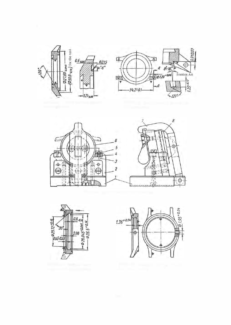
FIGURE 15.  Turning the  back shoulder 

(eighth operation) 

FIGURE 16.  Drilling holes for the strap bar 

(ninth operation) 

FIGURE 1 7 .   Jig for drilling the holes in the  lug 

FIGURE 18.  Boring the  move­
ment recess (tenth operation) 

FIGURE 19.  Drilling the winding-stem hole 

(eleventh operation) 

3 0 5  

The  tenth  operation  c onsists  in  turning the  recess  for the  m oment  (Fig­

ure  1 8 ).  A  form tool and either the  S- 1 7 5  or the  S - 8 1A  machine are  used 

for this operation.  The drilling of the winding- stem  hole  (Figure  1 9 )  by a 

special  horizontal  semiautomatic  drilling machine  follows  (eleventh  opera­

tion ) .   The  case middle  is  finally polished  (twelfth  operation )  and buffed  in 

a  longitudinal  direction,  and  then plated  (thirteenth operation ) .  

Cutting  conditions . 

The  cutting conditions  f o r  facing a n d  boring are 

established as a  function  of the machining  diameter,  the depth of cut,  the 

surface-finish quality  required,  and  the  tool  material . 

The  maximum  machining diameter  is  introduced into  the  formula for 

calculation of the  cutting speed.  Taking this  diameter to be 

3 0  mm  on 

the  average ,  and taking 

n =  

3 1 5 0  rpm  in the S- 1 7 5  m achine ,  we obtain 

3,1 4 · 30 · 31 50 

Vmax = 

1000 

::::::: 300 m

/

mm. 

The feed  rate  is  established as  a  function  of the  surface-finish quality 

required and  the  radius  of  curvature  of the  tool  cutting point .  In the  ma­

jority  of cases the  s urface is machined to a  class  6  or 7  finish  (see  Table 1 ). 

The turning  (basic )  time 

Tr 

is  determined using the formula 

-

l +  II +  12 

r

-

n · s 

• 

where 

turning length,  mm; 

!1 

tool  approach,  mm; 

!2 

tool o ve rtravel,  mm; 

s  = 

feed,  m m / rev; 

rpm .  

When working with  semiautomatic  machines ,   the  machine  cycle  time  is 

obtained by adding the  idle  cycle  tim e  

T

i

.

. • 

to  the furning time 

T

t

.  The 

idle  cycle  time 

Ti. 

c. 

is 

T·  = T . 

n i . c . 

1 . c . 

360" -

n i . c . 

where 

n � ,  c., = 

the  number of idle m ovement cam  degre e s ,   obtained  either 

from  the  technical  data  of the  machine  o r  from  the  setup  chart . 

The  piece  time  is  the  sum 

Tt  + 

Ti. 

c .  

+  Taux ;  Taux 

is  calculated  from the 

tables  of standards .  

The  parts a r e  s ubjected t o  a  random  inspection,  using both univers al 

and  specialized instruments,  after each operation.  C omparators ,  indicators, 

calipers ,  and  micrometers are examples of universal  instruments,  while 

plug  gages  and  templates  are  examples  of specialized instruments . 

The above - described machining p rocess has  the  shortcoming that the 

coefficient of metal  use  in the  strip  layout is only  33 o/o .   Simultaneous blank­
ing  of  middle  and  bezeF  was  proposed and  tested at  the  Watch  Plant No. · 2  

in  Moscow (Figure  2 0 ). 

The  method  of  simultaneous  blanking increases  the  coefficient  of  m etal 

use  to  7 0  o/o,  because  of the  additional  blank  and because  the  values  of the 

bridge  a1  between blanks  and  the  strip - edge b rige  a2  in the  strip  layout  is 

reduced  as  compared with  those given in F igure  1 1 ,  Chapter III. 

•  This method was proposed by M. 

I. 

Petetskii,  M. A .  Nesterov,  and A .  V.  Gorskii. 

3 0 6  

v ,  

m/min 

30-70 

A bove 

70 

3 � 70 

Above 

70 

3�70 

Above 

70 

TABLE  1 

Feed rates  for  machining NMTsS 63-17-18-2 nickel silver as a function of the 

cutting speed  and the surface-finish quality required ( abridged form) 

R9 and R18 tools 

VK6  and VK8  tools 

Surf ace-finish-quality class 

Radius of 

tool point, 

mm 

\l'V 

\l'V\1  7 

\1\1\1  8 

\l'V 

'V\1\1 7 

'V\l'V 8 

Feed rates,  s0,  mm/rev 

L o n g i t u d i n a l   t u r n i n g  

0 .018 

0.013 

0.009 

0.020 

0.015 

0.01 

0.3 

0.019 

0.014 

0.01 0  

0.021 

0.016 

0 . 01 1  

0.5 

0.020 

0.015 

0.01 1  

0.023 

0.018 

0.013 

0.8 

0.022 

0.01 7  

0.013 

0.025 

0.020 

0.01 5  

0.019 

0.014 

0 .010 

0.022 

0 .017 

0 .012 

0.3 

0.020 

0.015 

0.011 

0.023 

0.018 

0.01 3  

0.5 

0.022 

0 . 017 

0 .012 

0.025 

0.020 

0.01 5  

0.8 

0.024 

0.019 

0.014 

0.027 

0.022 

0.01 7  

F a c i n g  

0.016 

0.012 

0.007 

0.017 

0.013 

0.008 

0.3 

0.017 

0.013 

0.008 

0.018 

0.014 

0.009 

0.5 

0.018 

0.014 

0.010 

0 . 01 9  

0 .018 

0.012 

0.8 

0.019 

0.015 

0.011 

0.021 

0.016 

0.012 

0.016 

0.01.2 

0.008 

0.018 

0.013 

0.009 

0.3 

0 .017 

0.013 

0.009 

0.019 

0.014 

0.01 0  

0.5 

0 .018 

0.014 

0.011 

0.021 

0.016 

0.012 

0.8 

0 .019 

0.01 5  

0.012 

0.023 

0.018 

0.014 

B o r i n g  

0.010 

0. 007 

0.005 

0.012 

0 .009 

0.006 

0.3 

0.011 

0.008 

0.006 

0.013 

0.010 

0.008 

0.5 

0.013 

0.01 0  

0.008 

0.01 5  

0.012 

0.01 0  

0 . 8  

0.015 

0.012 

0.01 0  

0.017 

0.015 

0 . 012 

0 .011 

0. 008 

0.006 

0.01 3  

0.010 

0.007 

0.3 

0.012 

0.009 

0.007 

0.014 

0.012 

0.009 

0.5 

0.014 

0.012 

0.010 

0.016 

0.014 

0.01 1  

0.8 

0.017 

0.014 

0.012 

0.01 9  

0.017 

0.014 

307 

Punch  ( 1 )  and  die  (4 )  (Figure  2 1 ),  in  the  p roposed  die  s et,  pierce  the 

central  hole.  Punch  (2) and  dies  (3) and  ( 4 )  blank  the  case  middl e .  

Punch  (2 )  and  die  (4 )  blank the  bezel  which is then pressed back  into  the 

middle  blank by the  knockouts  ( 5 )  and  (6 ).  Sc rap  results  from  the hol e ­

piercing and i n  addition  the re  is  the  between-lugs  scrap  and  the  scrap 

a, 

and 

a2 • 

The  middle  blank  is  subjected  to  two  expanding operations  in  the  dia­

metral direction in  a  die  with a  tapered punch. 

The  expanding is  followed by lug-bending,  after  which  the  case- middle 

blank is  identical in shape  and  dimensions  with the  blank obtained  in the 

process  described above . 

FIGURE 

2 0 .  

Shape  of middle  and bezel 

FIGURE 

21 . 

Die for the simultaneous blanking of the case 

middle and the bezel 

Although  this  process  requires  the  additional  operations  of lug bending 

and bezel  ejection,  this  is  more  than compensated for by the  considerable 

economy achieved in  nonferrous  metal . 

Strap bars  are  an  integral part  of  the  case middl e .   Numerous  bar  de­

signs  exist and there are numerous  methods  of fastening the  bars to the 

watch  cas e .   The  design  of the  removable  bar  of the  "Pobeda "  watch case 

is  shown  in Figure  2 2 .   The spring ( 3 ),  compressed by the plunger  (2 ),  is 

introduced into the drilled hole in  the body  (1 ) .   The  hollow part of the bar 

is s o  necked that the clearance for the plunger is  reduced to  0 . 0 3 - 0 . 06 m m .  

3 0 8  


Content   ..  75  76  77  78   ..