Technology of watch production - part 49
Feed, mm
per blank
revolution
0,1 0
0.20
0.30
0 .45
0 .75
1 .35
TABLE 13
TABLE 14
Feed gearing
Hob-spindle speeds and cutting speeds
Gears
Hob-spindle
ZJ
z2
speed, rpm
24
84
500
36
72
700
48
60
1000
60
48
1400
72
36
2000
84
24
Technical data, model 530 machine
Maximum work diameter, mm
automatic operation
semiautomatic operation
· . . . .
Maximum hobbing length, mm
. • • • . . . . . • . .
Number of teeth hobbed
semiautomatic operation . . . . .
Maximum module, mm
. . . • • . . . . . . . . . . . .
Minimum module, mm
. . . . . . • . . . . . • . • • •
Hob diameter, mm
. . • . . • . . . . . • . • . . . . . .
Hob spindle tilt, degrees
. . . . . . . . • . . . . . . .
Electric motor pmver, kw
. . . . . . . . . • • . . . . •
Cutting speed,
m/min, for
cutter diameter
V =
24 mm
37 .8
52.8
75.5
1 05.5
150.8
25
50
40
6-100
6-300
0.05
25-30
Up to 3'
0.65
Speed of
electric
motor, rpm
1400
1400
1400
2800
2800
Hob cutters.
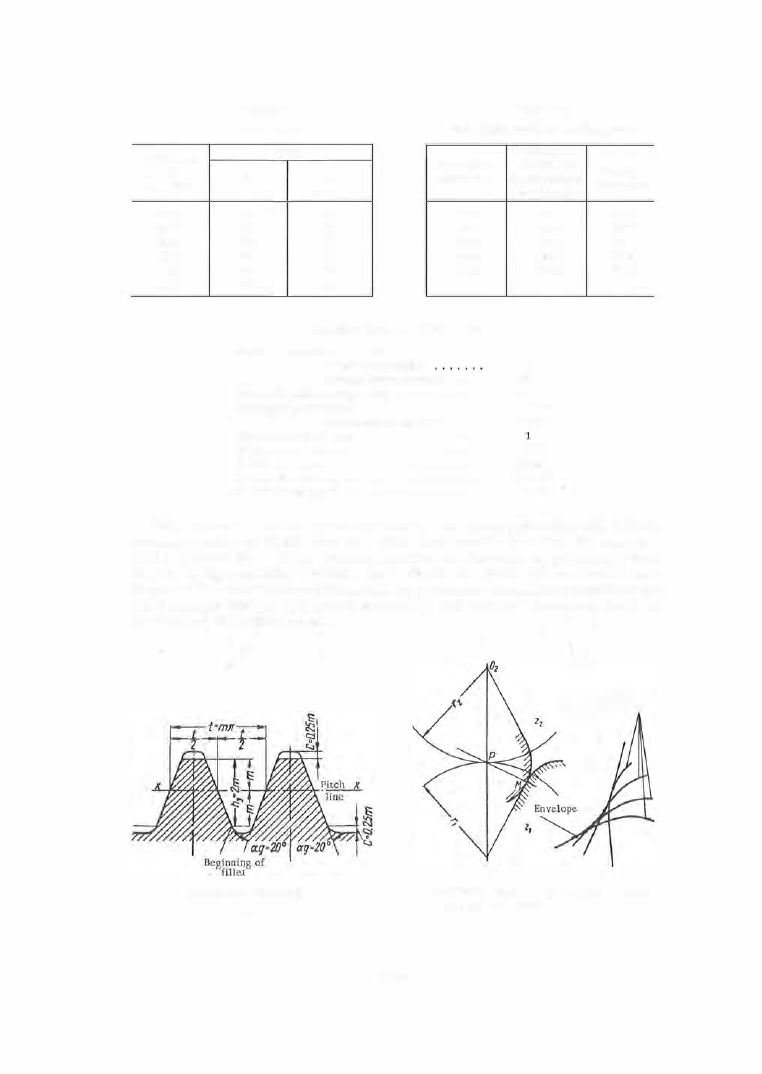
Involute gears are cut by bobs having straight- sided rack
teeth according to GOST 3 0 5 8 - 4 5 . This tooth profile is called the b a s i c
r a c k (Figure 2 5
).
Watch- gearing p rofiles are bobbed, as previously m en
tioned , by special bobs designed for each wheel . Since this method is us ed
in one of the most advanced branches of precision- instrument manufacture ,
the design of bobs is a practical necessity, and we shall therefore dwell on
the subj ect in greater length.
FIGURE 25. Basic rack
1 9 3
a
Family of plane
curves
F(x.IJ.C)·O
b
FIGURE 26. Envelope of the family of plane
curves - mated profile