Technology of watch production - part 48
 

  Index      Books     Technology of watch production (Tarasov) 1964 year


Search            


Content   ..  46  47  48  49   ..


Technology of watch production - part 48


The  required  relationship  between the  speeds  of  rotation  of  the  hob  and 

part  is  obtained by means  of change  gears  in the  hobbing- machine  gear 

train. 

In addition to  the  rotary motions  of  the hob and part,  the  machine table 

(or  the  hob  slid e )  is  fed  axially along the  work in order to  mill  the  length 

of  the  tooth .  

I n  the time  that the  wheel  rotates  b y  one  circular pitch  (tooth plus  space ) 

a  s ingle-thread hob  accomplishes  one  rotation.  Obviously,  the  axial lead 

of the  hob thread  ( the  distance between two threads  in the axial  cross  sec­

tion ) must be e qual  to  the  circular pitch of the  whe el .   This i s  the basic 

condition for the  relationship between the hob and the gear to be  mille d ­

t h e   l i n e a r   e q u a l i t y   o f   t h e   h o b   l e a d   a n d   t h e   g e a r   p i t c h. 

In  the  case  of  a  multi- th read hob,  one  revolution  of  the  hob  will  corre-

spond to.i._ revolutions  of the gear,  where 

is  the  number of threads  on the 

hob . 

The  hobbing m ethod  is  us ed in watch production for milling wheels  and 

pinions  with more than  12  teeth. 

Involute wheels  of the s am e  module but with different numbers  of teeth 

are  all  milled by the  same hob.  The involute  profile  thus m akes  it possible 

to  s tandardize  the  cutting tool .  Watch- gearing profile wheels  and  pinions 

are  each milled by a  special  hob . 

The  hobbing method is  not universal,  as  not all  gears  can be  hobbed .  

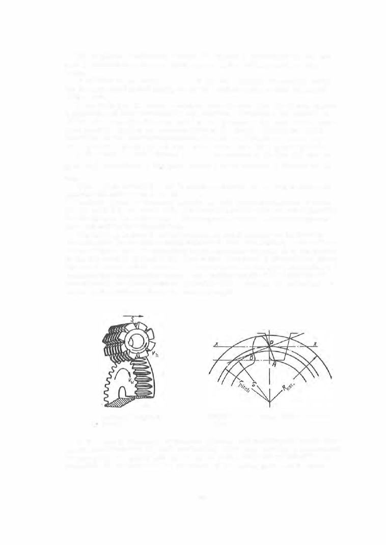
When involute  gears  with  a  small  number o f  teeth  are  hobbed,  undercutting 

occurs  (Figure  22 ) .   Undercutting is p res ent when the point 

on the  profile 

of the hob  tooth is  nearer to  the  gear  center than point 

(the  point  at  which 

the  line  of action 

BP 

is  tangent to  the  bas e  circle  of the  gear,  of  radius 

r0 

) .  

Considerable  undercutting  reduces  the  working length of the involute and 
thus  disturbs  the  s moothness  of operation of the  gearing.  In particular 

cas e s ,   undercutting  reduces  the  tooth s trength. 

Feed 

FIGURE  21.  Diagram of 
hobbing 

FIGURE  22.  Undercutting of an involute tooth for 

z <  

14 

In the  case of s tandard  2 0°  involute  gearing,  undercutting will  occur  when 

gears  with  fewer  than  1 7  teeth  are hobbed.  However,  hobbing is  considered 

as  acceptable  for gears  with as few as  14  teeth,  since the undercutting is 

negligible in that case and the tooth face of the mating gear can be made 

1 89 

with  a  circular arc  or  s ome other curve  instead  of  an involute.  The  trans ­
mission will  not  be  correct in  the  modified  s ector,  but  another pair of teeth 
can  be  meshe d  s imultaneously to  negate  the  error. 

P r o f  i 

e  c o r r e c t i o n  is used to reduce the undercutting at the tooth root 

in hobbing.  The  correction consists  in  increasing the  c enter  distance  of 

the m eshing pair by 

�A 

m  (this  is  acceptable  on  the  basis  of  design 

consideration) .   The  hob  is  withdrawn from  the  blank center by  this  same 

distance,  thus  increasing the blank  radius .  In  this  way  the  point 

on  the 

hob  is  withdrawn b eyond  the  point 

or to  a  point near 

B .  

When  the  hob  is 

thus  withdrawn 

its 

pitch line 

XX 

will no longer be tangent with the  wheel 

design pitch circle 

rp . 

The  hob pitch line  will  be  tangent  with  a  circle  of 

radius 

rp 

+ �A .  

The  form  of  the involute  is  not altered when the  c enter 

distance is increas ed as  it  depends  on the base  circle .  The active s ector 

of the  involute becomes  less  steep,  a  fact  which improves  the p roperties 

of the  gear pair and leads  to more uniform  wear on the p rofiles .  The  in­

volute  gearing in accurate  instruments which require high  gear  efficiency 

is  corrected according to  this  method .   I f  a  correction i s  impos sible,  wheels 

with fewer than  1 7  teeth should be form - mille d .   The design drawing must 

take  into  account  the  neces sity  of  correction. 

When hobbing watch- gearing p rofile pinions  with between  6  and  12  teeth, 

the acute tip  of the hob tooth  (at an unfavorable  depth-to-width ratio )  is  rapid­

ly worn,  and the tooth space  obtained has an incomplete  depth  (Figure  2 

3 )

The  530 semiautomatic  gear-hobbing machine 

was  designed for hobbing 

s mall- module spur gears  and pinions  and  is locally p roduced.  The  machine 

is  available  in  several  versions  and can ope rate  automatically. 

The  kinematic  s cheme  of the  machine  is  given in  Figure  2 4 .  

Power from  the  electric  motor i s  transmitted through  a  V-belt  from 

the  three - s tep pulley  ( 1 )  to  the  thre e - step pulley  (2 )  on the  driveshaft I .  

One  end o f  the  driveshaft is  connected through a  telescoping shaft t o  the  hob 

spindle.  The  work-spindle  change  gears  are  connected to  the  s econd  end 

of the  drive  shaft.  The  change  gears  (a ,  b ,  

c ,  

d )  

drive  the  worm  shaft  II , 

which carries  a  single-thread (or five-thread )  worm  ( 3 ),  and  which in turn 

drives  the  work-spindle  worm  gear 

( z  = 

5 0 ).  The  use of a  singl e - thread 

worm  makes it possible to  obtain  gears  of high angular-pitch accuracy, 

while the  use  of a  five -thread worm makes  it possible to mill pinions  with 

6  teeth,  thus  considerably increasing the  range  of  this  machine  (most watch ­

mechanism pinions  have  between  6  and  1 2  teeth). 

The  work spindle  carrie s ,   in addition to the  worm wheel,  an 1 8-tooth 

helical  gear which  m eshes  with  a  6 0-tooth helical  gear on  shaft III.  The 

feed change  gears 

z1 ,  Zz 

are located on the  shaft III  and the  worm  shaft IV. 

The  worm  shaft IV carries  a  single-thread worm  which  drives  the  worm 

wheel 

fastened  to the  feed  shaft V .   A  1 4-tooth helical gear,  permanently 

meshed with a  rack,  is  fitted to the  right end of shaft V .  

The  rac k  is fastened to  the  machine  slide .  The  14-tooth helical  gear 

can grip the  shaft V  by m eans  of a  conical  bushing and  rotate  together  with 
it,  fo rcing the  slide to  advance .  When the  link  between the  conical bushing 

and  the  gear is  released (by manual  action) the  latter sits  freely on  the  shaft, 

and  the  s lide  does  not move. 

The slide is  returned  after hobbing by m eans  of two springs  located inside 

the bed. 

1 9 0  

FIGURE  23.  Insufficient tooth space as a result of the blunting of the hob tooth 

W ork-spindle change gears 

Feed 

FIGURE  24.  Kinematic scheme of the 530-machine model 

1 9 1  

Coolant 

pump 

The  work-spindle  change  gears  are  s elected according to  the  following 

formula: 

5'0 

T �t = -z ·  

where  z  =  the  number o f  teeth  on the  wheel  to b e  hobbed. 

The following equality  exists  for a  constant  center distance  for gears  a 

and  b :  

z., 

z0 = 125, 

(the  s um  of  the  numbers  of  teeth  on  gears  a and  b  is  1 2  5 ). 

Three  or four  gears  can be  used: 

When working with three gears  a- b- d: 

a = 50  

25; 

b = 75 

100; 

d= 

Zcut 

Z cut 

When working with four  gears  a - b - c - d: 

a = 50  

25; 

b = 75 

100; 

c = 25 

50; 

Zcut 

Zcut 

d = a 

The  gears  available  for the  machine  are: 

1 )   a  set of  93  change  gears 

d ,  

beginning with  z = 24,  36,  40 and up to 

1 3  0; 

2 )   two  step  gears 

b/c 

7 5 / 2 5  and  1 00 / 5 0 ;  

3 )   two  gears  f o r  a  and 

c ,  z 

= 5 0  and 

=  2 5 .  

When working with three  gears  a - b 

-

d  the  gear 

s e rves  as  an  idler 

only,  revers ing the  direction of rotation  of gear d .  

The  feed gearing cons ists  of two  change  gears 

Z1 ,  Zz 

• 

Six pairs  of 

change  gears  provide six feed s teps  between  0 . 1  and  1 . 3 5  mm per blank 

revolution. 

The feeds  corresponding to  different  combinations  of the  change  gears 

are  given  in  Table  1 3 .  

The  number o f  feed s teps  can b e  increas ed by the  us e  o f  additional  gears 

z1  ,  z2 . 

The  three- step  belt transmission from  the  motor to  the  driveshaft pro ­

vides  three  hob  speeds .  Since  the  electric  motor itself  has  two  speeds ,  the 
total  number of hob-spindle  speeds is  6 .  

The  motor pulley has  a  fourth  step for powering the  coolant  vane  pump. 

The  teles coping shaft m akes it possible to feed the hob slide in the ver ­

tical  and i n  two  horizontal  directions . 

1 9 2  


Content   ..  46  47  48  49   ..