Technology of watch production - part 46
 

  Index      Books     Technology of watch production (Tarasov) 1964 year


Search            


Content   ..  44  45  46  47   ..


Technology of watch production - part 46


The  idle-cycle  time  and  the  machine-s etup  time  must be  added to  the 

milling time  calculated  according to  (2 

)

The  idle-cycle time  is  determined 

from the technical  data of the  machine.  For  the  S - 4 0  machine  the  idle 
m ovements  take  roughly  7 %  of 

m . 

Having calculated  the  machine-cycle  tim e 

Tmach=  T m 

+  T 

for machin-

ing one part,  it is  compared with the  technical data of  the  machine,  and the 

camshaft speed closest to  that  which  would  give  one  camshaft  rotation  during 
T

mach

is  s elected.  The  calculated  cutting speed is  also  compared with the 

machine  capabilities  and  the  closest available fo rm - cutter spindle  speed is 

s elected.  The method of calculation of the  cutting c onditions  and  the  ma­

chine production rate  will  be illus trated  in the following example . 

It is  required to mill  the teeth of a third-wheel pinion of module  0.103 mm, 

z = 

8 .   The length of cut 

is 

I =  

0.80 mm,  the material U7A V steel. 

The data necessary for the calculation are first written down. 

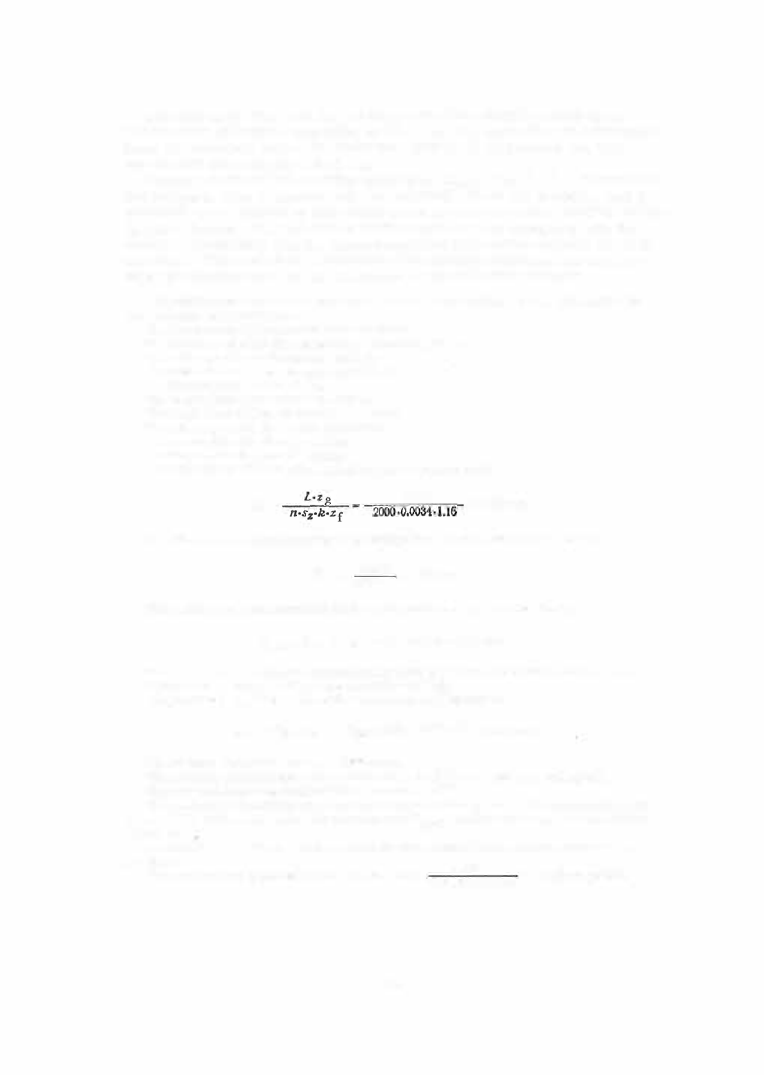
The feed per tooth of the form cutter is 

Sz 

0 .0034 mm (Table 8). 

The cutting speed is 

fl 

50.3 m/min (Table 9). 

The form-cutter dimensions are taken from Table 4 :  

diameter 8 mm,  1 6  cutter teeth. 

The cutter-spindle speed chosen is 

n = 

2000 rpm. 

The length of cut is,  from the drawing, 

I =  

0.8 mm. 

The cutter approach is 

/1  = 

1 .5 mm (Appendix 3), 

The overtravel is selected as 

/2  = 

1 .2 mm. 

The total travel is therefore 

3.5 mm. 

The time required 

for 

milling the pinion in one pass is according to (2) 

T. 

3.5 · 8  

0'25 

mm. 

The idle movements taking, according to the  machine data,  7 o/o  of the  milling time,  we have 

0.25 .7 

0  2 

Ti 

IOO 

.0 

mm. 

The machine-cycle time required for  machining the pinion in one pass will therefore be 

Tmach = T m  + T i 

0.25 

0.02 

� 

0.27 

min. 

If two passes are to be made, we must add the time taken by the form-cutter shifting which requires one 

camshaft revolution.  At naux 

20 rpm this takes  1/20 

0.05 min. 

The piece time, 

p•  for one cycle of the S-40 machine will therefore be 

Tm + T i 

Taux = 

0.25  +  0.02 

0.05 

0.32 

min. 

For two passes,  this time is doubled,  and is 0 .64 min. 

The calculated production rate of the machine will 

be A =  ..i§.Q. 

750 pieces per working shift. 

The data obtained are then compared with the machine dat

g

:64 

The  camshaft speeds available  are  n 

9,  19.2  or 3 0 rpm ;  the time per  camshaft revolution will accord­

ingly be :  0.11,  0.052 , or 0.033 min.  The calculated time T mach  required for milling one tooth is 0.27/8 

0.034 min. 

According to the specifications of the machine, the value closest to this is 0.033 min, corresponding to 

n= 

30 rpm. 

480 

The actual machine production rate will therefore be 

A = 

2 ( 0.0033 .8 

0.05) 

764 pieces per shift. 

1 8 1  

The  pinion blanks  obtained from  Swiss - type  automatic  screw machines, 

and  the  wheel blanks  obtained  from  high- quality s tamping dies,  have  min­

imum milling allowances .  The diameter allowances for s teel pinions  are 

s et  at 0 . 05 to 0 . 1 5 mm ,   for brass  wheels  at  0 . 0 7  to  0. 2 0 mm ,   and for steel 
wheels at  0. 1 5  to  0 . 3 0 mm. 

The  surface -finish quality of form -milled bras s  and ste el  pinions  and 

wheels  of  0 . 05  to  0. 3 mm  module is  class  8  or 

9, 

and that  of whe els  of 

0 . 3  to  0 . 5  mm module  is  class  7  or  8 .  

MILLING  FACE  (CONTRA TE)  TEETH 

The  milling  of face  teeth on the  crown wheels ,  winding pinions  and claw 

clutches  of watch mechanisms,  and  on other s imilar parts ,  is performed 

on S - 51  and S - 1 8 6  copy-milling and  indexing machines . 

FIGURE 16 .  S-186-type face-gear milling machine 

The  S - 1 86  is  the  most versatile m odel 

(

Figure  1 6

)

The  S - 5 1  machine  is  s emiautomatic;  8 mm  is  the  maximum  wheel  dia­

meter and  0 . 3  mm is  the  maximum  module  which  can be  milled  on this 

machine . 

The  S - 1 86  machine  is  s emiautomatic  but  can  als o  operate  automatically 

with one  disk  cutter .   Milling  can be  carried out in two passes .  The  s emi­
automatic  machine  has  horizontal  and  vertical  feeds for infeed face milling 
and cross -feed milling,  respectively. 

Infeed  milling is  used  when cutting teeth of negligible l ength and  open 

profil e .  

1 82 

C ross - feed milling is  used when cutting teeth  of  considerable  length  or 

teeth  with an undercut  profile  (ratchet teeth ).  In the latter case the  head ­

s tock with  the  form  cutter s wivels  up  to  5°. 

Cros s - feed milling gives  a  better s urface-finis h  quality and a  m ore ac ­

curate p rofile  than  does  infeed milling.  The  m achine  operates  automati­

cally when milling parts  of a  diameter s maller than  9 mm,  and s emiauto ­

m atically when  milling larger parts  of  diameters  up  to  2 5  m m .   The  manual 

loading of  blanks  is  performed by a  special  loading carriage  which  feeds 

them to  the  collet.  The  ej ection of the parts  is  performed automatically. 

FIGURE  1 7 .   Position  of the form cutter  in milling : 

a-cross-feed milling;  b-infeed milling. 

The  kinematic  diagram  of  the  S - 1 86  m achine  is  given in Figure  1 8 .   The 

m achine  is  driven by an  electric  motor placed inside the machine  bas e .  

The  cutter-spindle pulley  ( 5 )  i s  powered b y  a  round belt from  the  first 

s tep  of the  electric - moto r  pulley  (1 ),  through  the  counters haft pulleys  ( 3 )  
and  (4 ). 

The speed of  rotation can be increas ed by  changing  pulley  (4). 

Electric motor 

Worm-wheel 

shaft 

Work spindle 

Gear-pump shaft 

FIGURE  18.  Kinematic diagram  of the S-186  machine 

1 83 

The  worm-shaft pulley  (2 )  is  powered from  the  s econd s tep  of the electric ­

motor (pulley  ( 1  ).  The  worm  and  wheel  ( 1 1 - 1 2 )  trans mit  power to  the 

worm - wheel s haft. 

The  worm - wheel  s haft powers : 

a )   the  camshaft through  the  change  gears  ( 7 )  and  ( 9 )  and  claw clutches; 

b )   the auxiliary s haft through  the  fixed  gears  ( 1 3 )  and  ( 1 0 )  and  claw 

clutches .  

The  camshaft and the  auxiliary s haft  operate  successively .  The  cam­

s haft has  six speeds while the auxiliary shaft  rotates  at a  fixed speed. 

The  cams haft powers  the  gear pump  through  a  gear  s et,  and  is  s tarted 

and  stopped automatically by m eans  of claw clutches  controlled by the  cam 

on  the  auxiliary  s haft.  The  auxiliary s haft  is s tarted by the  catch on the 

dividing-head  gear  ( 8 ),  and  stopped by  cam  I,  which  is  integral  with the 
one -turn claw  clutch on the  auxiliary s haft. 

Auxiliary shaft 

FIGURE  19. 

Work spindle 

The  fixed  cams A ,   B ,   and  C ,   which  control the  working process es  of 

the  machine  are  mounted on the  camshaft. 

Cam  A ,   a  bell  cam ,  controls  the  cutter  feed  in the horizontal  direction 

for infeed milling and in the  vertical  direction for  c ross -feed milling. 

Cam  B,  a  flat  cam ,  locks  the  index plate in position. 

Cam  C,  also  a  flat  cam ,  indexes the index plate. 

One tooth is  milled per camshaft  revolution,  and  the  whole  gear wheel 

is  milled  during one  rotation  of the  index plate.  When  the  milling is  done 
in two stages  (roughing and finish )  the  index plate  executes  a  second rota ­

tion,  and  the  milling  cycle  is  repeate d .  

When the  milling  has  been  completed,  the  camshaft i s  s topped,  and  the 

auxiliary shaft s tarted.  The auxiliary  shaft  mounts  the cams  D,  E ,   F,  G, 

H,  I ,   J  and K  which  control  the  auxiliary machine  functions . 

1 84 


Content   ..  44  45  46  47   ..