Technology of watch production - part 45
The s e rvice life of the finishing cutter is the s ame regardless whethe r
two or three passes are made, s ince the slotting cutter facilitates only the
work of the roughing cutter. The s ervice life of s lotting cutters is lower
than that of fo rmed gear cutte rs . The s ervice life of the finishing cutter
(between regrindings ), when milling wheels and pinions made of Ul OA s teel,
is 7 to 8 hours machining time.
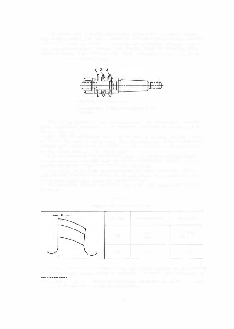
FIGURE
1 5 .
Mandrel with cutters :
1-slotting cutter; 2-gear cutter ( roughing); 3-gear cutter
(finishing).
The milling conditions - the feed and speed - are s elected as a function
of the mechanical properties of the material, the blank dimensions and the
cutter material .
If we take the cutting speed of a cutter made of an alloy tool steel such
as KhVG, Kh, etc . as b eing unity, then the cutting speed for cutters made
of high - speed steels such as R 1 8 will be 1 . 5 , and that of cutters made of
carbon steels such as U 1 2A will be 0 . 9 .
I t i s recommended that alloy-s teel cutters b e us ed for milling brass
wheels and pinions and that high - speed- steel cutters ':' be us ed for milling
wheels and pinions made from U l OA or U 7A V steel .
The cutting edges of the cutter teeth become worn during the milling
process and wear is most s e vere at the tooth point, the specific load there
being much higher than along the lateral surfaces .
The criterium for tooth blunting is the width of the wear land b, given
in Table 5 .
TABLE
5
Acceptable value of cutter-tooth blunting
Cutter type
Hob
Disk
Material machined
Steel
Ilrass
Steel
Wear b, mm
0.15- 0.25
0.07- 0.1 0
0
.
1
-
0
.
2
Feeds .
The feed rate is established, as already mentioned, as a function
of the mechanical prope rties of the material , the module and the number of
0
The method of manufacturing cutters from the
VK6
hard alloy has now been mastered. The service life of
such a cutter is several times longer than that of earlier cutters.
177