Technology of watch production - part 29
 

  Index      Books     Technology of watch production (Tarasov) 1964 year


Search            


Content   ..  27  28  29  30   ..


Technology of watch production - part 29


Small  surfaces  o r  recesses  are  machined by  plunging  tool  No .  2  while 

the  heads tock  is  s tationary . 

The  rocke r  is  so  des igned  that  the  feed  motion  of  tool  No .  2  and  the 

withd rawal  of  tool  No .  1  are p roduc ed by  the  rocke r  cam ,  while  the  with­
d rawal  of  tool  No .  2  and  the  feed  motion  of  tool  No .  1  are  induced  by a 
spring.  Tool  No .  1  is  not us e d  in plunging  ope rations ,  s ince  the  sp ring 

p ressure  could  bend  the  part  or  break  it.  Ins tead  of  being cam - actuated, 

tool No .  1  can  also  operate  on a  fixed s top ,  a  p rocedure  used fo r  machin ­
ing  the  most accurate  s urfac es . 

Tool  No .  1  can  turn  s e ve ral  diam ete rs  in  succession.  When one diameter 

is  finis hed,  the tool  retreats  the  neces sary  dis tance  while  the headstock 

dwells .  When the tool is  pos itione d for the s e cond 

r-··· 

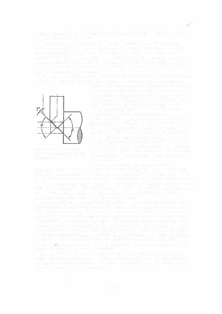
FIGURE  1 7 .   Scheme  of cut-off 

with  tool  and  headstock moving 

simultaneously 

diameter,  the  heads tock begins  to  advance . 

F o r  tap e r  turning,  tool  N o .   1  and  the  head­

s tock move  simultaneously and  uniformly.  Con­
toured surfaces  of a�y  desired  shap e  are  ob­
tained by  fe eding the tool and heads tock  simul ­
taneously at  s uitable  different  spe eds . 

Rear - end  tap e r  turning is  p e rformed by the 

simultaneous  fee ding of the  heads tock  and  tool 
No .  4 .   Cone fo rmation a t  cut- off  is  shown  in 
Figure  1 7 .   The  front - end  cone  in  the  following 
part  is  obtained by  suitably  grinding tool  No .  4 .  

I n  order t o  obtain a  sharp  ap ex in  the  front- end 

cone ,  the  tool  ove rruns  the  axis  by  0 . 1 - 0 . 2  m m .  

The  s ketch  of the  blank  given  o n  the  operation 

sheet  specifies  a  blank length which allows  fo r 
the  o ve rrun . 

The  rear  cutting edge  of  the  cutter has  a 

clearanc e  angle  of 

to  5°  in  o rder to  avoid  rubbing  the  enti re  cutting edge 

along  the  cone  surfac e .   The  cone  surface  obtained  by  s imultaneously feed­

ing the cutter and heads tock is  somewhat  s e rrated as  a  res ult  of tool  traces . 

Some  watch pa rts  have  chamfe rs  with  dimens ions  ranging f rom  0 . 0 5 mm X 

X 4 5°  to  0 . 1 5  mm X 4 5 ° .   Such  chamfe rs  are  m ade  either by  the  combined  m o ­

tion  of cutter  and  heads tock  o r  b y  a  s uitably  ground  cutter  cross  f e d .   In 

the latter case  slides  No . 

o r  No.  5  can  be us e d .  

It is  s ome times  more  expe di ent t o  p roduce  a  chamfer b y  us ing the  c o m ­

bined  motion  of  cutter  and  heads tock.  Such a  cas e  is  shown in Figure  3 1  

( 9th  operation ),  where a  0 . 0 6 m m X 4 5 °  chamfer is  p roduc e d .   In this  cas e 
cutte r  No .  1  has  a  continuous  backward  motion  during  the  form ation  of  the 
shoulder  and  the  chamfer;  the  heads tock  advances  continuously from  the 

beginning  of  the  chamfering till  the  turning operation  is  completed.  When 

a  s eparate  tool  is  us ed fo r  chamfering,  additional  tim e  must  be  expended 
on its  approach and plunge ,  as  can be  s een from  Figure  3 1  ( 1 6 th  ope ration ) .  

In addition,  one  of the  tool  s lides  is  occupied b y  the  chamfering tool . 

The  largest diameter of  a  p art  is  s ometim es  not  turned,  s ince  the  bar 

s tock can have  the required diameter. 

In  cases  where the part is  subjected to heat treatment,  howe ver,  or 

where the l argest diam eter is  a  mating surfac e ,   the bar mus t  be  turned  on 
the  largest  diameter in  order to  remove  surface  s c al e  o r  to  attain a  higher 

degree  of  conc entricity,  respe ctively. 

1 1 3 

Undercutting  is  usually p e rformed by  tool  slides  N o .   4  o r  No .  5 .   The 

cutte r  is  pos itioned  fo r  the  operation by  a  cam .  The  headstock is  then  ad­
vanced to the  undercutting depth,  and is  withdrawn  when  the  undercutting 

is  complete d .   The  cutter  then  retreats  to  its  initial position.  The  s hape 

of the undercut is  the  s am e  as  the  shape  of the cutting tool .  Underc utting 

can  also  be  p e rformed by  means  of  tools  mounted  in  the  horizontal  slides 
of an auxiliary  attachment  (Figure  1 8 ).  Slides  ( 1 )  and  (2 )  are actuated 

through the levers  ( 5 )  and  (6 )  by  the  bell  cams  ( 3 )  and  (4 )  on the  camshaft. 

The  slide  carriage  ( 8 )  is actuated by the flat  cam  (7 ) . 

FlGL!I\E 18.  Attachment  1vith  two  horizontal slides for  undercutting 

Back  rec essing,  especially  of deep  recesses ,  should  not  be  attempted 

on  this  type  of automati c  s c rew machine,  as the cutting  will  take  place  at 

a  conside rable  dis tance  from  the  guide bushing,  and  the  headstock,  during 

the plunge,  is  withdrawn by  a  s trong sp ring.  This  can lead to b roken  cut­

ting tools .  Parts  having  a  back  recess  must the refore  be  sta rted from  the 

recess  side.  On  the  s trength  of thes e  considerations  the  machining of the 

central pinion is started at the sho rt end (see operation sheet on pp .  1 42 - 1 4 3  ) .  

Depending o n  the  configuration of the  part,  the  cutters  can  work i n  a 

diffe rent  order as  well .  For instance,  the  cut- off  may  be  p e rformed by 

cutter  No .  4  o r   5 ,   and  the  recessing by  cutter No .  3 .   The  dis tribution  of 

wo rk among the cutte rs  is  explained below. 

D r  i 

1 1  

i n  g .   Holes  are  drilled by  attachments  mounted  on the left  part 

of  the  bed in front  of  the  tool head .  The  drill ed hole  must be concentric 

with the  outer surfac e s ,   and  accordingly  the part  must be accurately  c ente r ­

drilled  (c ente red )  before  drilling. 

1 1 4 

The  part  is  c entered  either by  one  of  the  vertical  cutters ,  by a  c enter 

drill  mounted in a  holder in  a  vertical  slide  (see Figure  1 9 ),  or by a  cente r 

drill  mounted  in  one  of  the  spindles  of  the  attachment.  Centering  with  a 
cutte r  is  more  accurate ,  although  it  involves  a  greater time  expenditure .  

FIGURE  1 9 .  

Holders : 

a-for  a center drill;  b-for  a carbide-tipped 
tool;  c-for  a  common  cutting  tool. 

Drilling without  first centering is  acceptable  only if the  hole  depth  does 

not  exceed two  diameters  and if a  s trict concentricity between the hole  and 

the  outer surface is  not  required.  The  concentricity  of the  attachment and 

heads tock spindles  is  very  impo rtant when  holes  of  a  depth  of more  than  two 

diameters  are  drilled. 

In o rder to inc reas e  the  p roductivity  of the  machine ,  c entering o r  drilling 

mus t  be  combined  with  other  operations  as  much  as  poss ibl e .   Drilling,  fo r 

instance ,   can  be  combined  with  turning.  In drilling one  must  take  into  ac­

count  that the total  feed of  the  d rill and the headstock must not exceed the 

admissible  feed  magnitude .  

C entering and  drilling will  be accomplished  with  the  highest degree of 

accuracy if the  operation is  started before the  bar  leaves  the  guide  bushing. 

A  drilling ope ration  should not begin with a  cons iderable  length of bar 

protruding from the  guide bushing as  the  blank is  then less  stable  and the 

machining m ight be  inaccurate .  It  is  not  recomm ended  to  combine  drilling 

and  radial- feed machining. 

FIGURE 

20.  Layout of bell spindle feed  cam for drill attachment, with recesses for  retracting the drill 

1 1 5 

Stepped holes are d rilled using two - ,  three - ,   and four- spindle attachments .  

The  last spindle  can b e  us ed for facing.  Stepped  holes  are best d rilled by 
s eparate  drills ,  and  not  by  s tep  drills ,  in  o rder to  achieve  accurate  dia­

meters  and depth for  each step.  Straight- flute  drills  are  generally us ed 

for drilling holes . 

Blind holes  and  s tep  holes  with  close  depth  tole ranc es  are  drilled  using 

the  heads tock feed.  Spindl e  feed  is  used when  a  through hole of uniform 
diameter is  drilled. 

In d rilling deep  holes ,  the  drill  is  retracted many times  in order to 

remove  the  chips  and  to  cool  the  drill .  The  deeper the  hol e ,   the  more 

frequent  the  retractions .  The  following  relationships  have  been  empirically 

es tablished between the  drill  diameter,  the  hole  depth,  and the  number of 

retractions  of the  drill: 

Retraction  . . . . . . .  First 

Drilling  depth  . . . . .  3d 

Second 

5d 

Third 
6 .5d 

Fourth 

.5d 

Fifth 
8 .5d 

The  bell cam which feeds the spindle of the  drilling  attachment has  s uitable 

recess es  for  retracting the spindle  (Figure  2 0 ) .   It is,  however,  more 

expedient  to  retract the drill  by means  of a  special  cam  mounted on the 

back  wall  of the  bed  (see Figure  1 3  

)

T h r e a d   c h a s i n g   is  carried  out  on automatic  s crew m achines  using 

the  differential  method,  also  called the  o verrunning m ethod.  The machine 

spindle  rotates  at the  same  speed and in  the  s ame s ens e  as  in turning while 

the  spindle  carrying the  chasing die  ro­

tates  in the  s ame  s ens e,  but at a speed 

� 

· 

which  is  higher  than  that  of  the  machine 

spindle when  chasing a  right- handed 

thread,  and lower when chasing a  left ­

handed  thread.  The  speed  of  thread  chas ­
ing is  equal to  the  difference between the 

spindle  speeds . 

When  the  chasing of  a  right- handed 

thread has been  completed,  the chas e r  

begins  t o  rotate  m o re  slowly then  the ma­

chine spindle,  and  thus  unscrews  itself. 

The s am e  effect is  achieved in chasing 

a  left- handed thread by  reversing the 

s equence. 

FIGURE 21 .  Thread-chasing  attachment drive 

The  differential  method of thread  chas -

ing has  many advantages  over  the  m ethod 

used in  turret automatics ,  where  the  machine  spindle is  revers ed and 

slowed  down and  the  chasing  die  or  tap  is  fixed in  the  turret  head  and  has 

only  a  translato ry  motion.  The  s witch- over of the  machine  spindle  takes 

time  and  the  design  of  the  machine  spindle  ass embly is  much more c omplex. 

Left- hand threads  are chased using the same attachm ent  as  for  right­

handed threads  with  only the pulleys  on the  machine m ain  drive  shaft chang­

ing places  (Figure  2 1  

)

For thread  chasing,  the  headstock must first advance 

to  8 mm  at high 

speed,  s o   that  the  cutters  will  not  p revent  the  chas e r  from  advancing along 

1 1 6 


Content   ..  27  28  29  30   ..