Technology of watch production - part 27


  Index      Books     Technology of watch production (Tarasov) 1964 year


Search            


Content   ..  25  26  27  28   ..


Technology of watch production - part 27


All  the  working mechanisms  of  the  machine - the  headstock on  the  right, 

the  d rilling and  threading  attachments  on the  l eft,  and  the  tool  head in the 
middle - are  mounted  on the  b e  d.  The  camshaft is  mounted on the  rear 

side  of the  bed and  carries  cams  which control  the headstock feed,  the feeds 

of the uppe r  tool slide,  the rocker,  the spindles  of the drilling and othe r 

attachments ,  and  the  closing and  releasing  of  the  collet. 

The camshaft is  driven by the trans vers e  s haft  VII,  mounted inside the 

bed  (Figure  6 ).  A  two-step  pulley  turns  freely on  one  end  of this  shaft while 

a  handle  is  fixed  to  its  other  end by m eans  of which the  camshaft  can  be 

m anually  rotated when  the  machine  is  being adjusted. 

The worm,  with  s imple  jaw  clutches  at both end s ,   turns  freely  on the 

transvers e  shaft. 

The  cam shaft is  rotated by the pulley when the worm  clutch engages 

the  latter,  and m anually when the  worm  engages  the  trans vers e  s haft. 

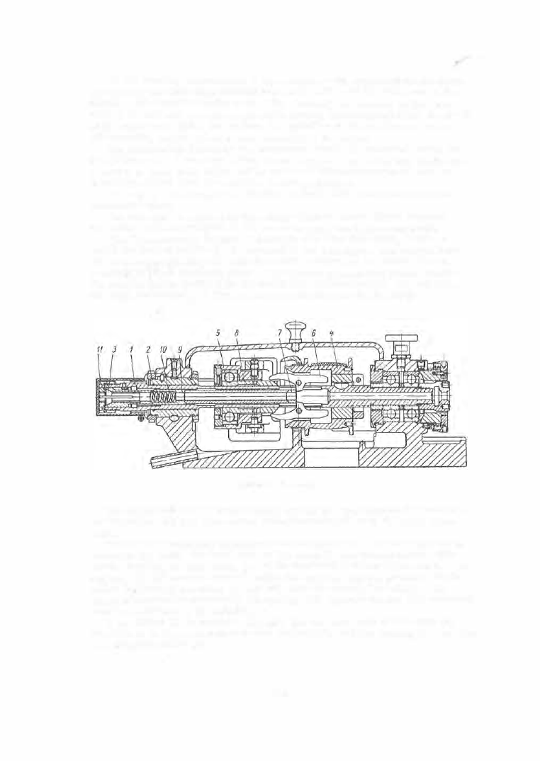
T h e   h e a d s t o c k   (Figure  7 )  consists  of a  cast-iron body,  inside  of 

which  the  hollow spindle  ( 1 )  is  mounted in  two  bearings .  The  frontal bear­

ing is  a  bronze  bushing  (2 ),  and the rear bearings  are two radial- thrust 

bearings  of the A  accu racy  clas s .   The bar b eing machined passes inside 

the  spindle and  is  clamped by  the  collet  (3 ).  The pulley  (4 )

rotated from 

the  main drive  s haft,  is fixed on the  spindle  between the bearings . 

FrGURE  7 .   Headstock 

The  headstock moves longitudinally during the  operation of  the  machine, 

and  therefore the b elt als o  m oves  along the wide pulley of the main drive 
s haft. 

The  collet  mechanis m  is  mounted  on the  spindle  (1 ).  If the  slider  (5 )  is 

moved  to the  right,  the  front  ends  of  the  cams  ( 6 )  are  forced  apart.  The 

cam s ,   rotating on their axes,  press  the  hardened bushing  ( 7 )  forward.  The 

bushing  (7 ),  by moving fo rward  inside  the  spindle ,   applies  pressure  on the 

collet  ( 3 )  through  the  tubes  (8 )  and  (9),  thereby  closing the  collet.  The 
collet is  constantly pressed by  the  sp ring  (1 0),  against  the  nut  ( 1 1  ),  screwed 

onto  the  front  end  of the  spindle. 

If the slider ( 5 )  is  moved  to the left,  the forward  ends  of the cams  ( 6 )  

are  able  to  be  drawn  together by  the  spring  ( 1 0 ),  and  the bushing  ( 7 )  retreats , 

releas ing  the  collet  ( 3  )

1 0 5  

The  motion of  the  slider  ( 5 )  to  the  right  and  l eft is controlled by the  fixed 

cams  ( 3 )  and (4 )  on the camshaft through  the fork  lever (6 ) 

(

Figure  8 ).  A s  

the headstock moves longitudinally  during the machine ' s  operation and  the 
cams  which  open  and clos e  the  collet are fastened in a  fixed position on the 
camshaft,  the l ever  ( 1 )  is provided with a  channel  slot in which slides  the 
pin  (2 ),  held  by  the  nut  (7 

)

.  The l ever  ( 1 )  turns  about an axis  mounted  on 

the m achine bed, 

FIGURE  8 .   Design o f  the  chucking system 

The  leve r  ( 1 )  carries  the  pins  (8 )  and  (9 

)

,  which are  engaged  by the 

cams  ( 3 )  and  (4 ),  fastened  on the  camshaft.  The  cam  ( 3 )  releas es,  and  the 

cam  (4 )  closes  the  c ollet.  The cams  are  so  s et  on the faces  of the  disk ( 1 0 )  

that they  close and  releas e  the  collet at  d efinite points  i n  the  m achining 

cycle .  

The  headstock i s  actuated through  a  feed mechanism by the plate  cam  B 

on  the  camshaft 

(

Figure  9 )

The  cam  B ,   acting  on  the  follower 

(1 

),  rotates 

the  leve r  C  about its  axis  (2 ).  The  roller  ( 3 )  on the lever C  comes  into  con­

tact with the rolle r   (4)  on the lever D .   The  lever C  rotates  i n  a  vertical 

plane p e rp endicular to  the  spindle  axis  while  the  lever D  rotates  in a  verti ­

cal  plane parallel  to  the  spindle axis .  When  the  roller  ( 3 )  is  lifted,  the 

lever D  rotates  to  the  left  about  axis  ( 5 )  which  is  fas tened  to  the  machine bed. 

The  axis  of the  roller ( 6 )  is  held in the slot of the  leve r  D.  The  roller (6 ) 

engages  on  the  cleat  ( 8 ) ,   mounted  on  the  lateral  face  of  the  heads tock body. 

When the  l ever D  is  rotated to  the l eft the roller  (6 )  feeds  the  heads tock 

forward.  The  transmis s ion  ratio  of the  two arms of the  lever D  can be 

varied from  1 : 1  to  1 : 3  by m eans  of the  s crew  ( 7 ) .   The  headstock is  returned 

by m eans  of a  spring. 

Two  headstock-feed plate  cams  for  machining two different parts  can be 

mounted on the  camshaft .  Two followers  ( 1 )  are  mounted on the  lever  C 
and when  the  machine  is  changed over from  one part  to  the  other,  the  ap ­

p rop riate  follower is  lowered s o   that  it  does  not engage  its  cam ,  while  the 

other follower  is  lifted  till  it  engages  its  cam . 

T h e   t o o l   h e a d ,  sometimes  called the tool pos t by  analogy with  the  en­

gine lathe,  is a complex iron casting m ounted on the machine  bed 

(

Figure  1 0 ) .  

1 06 

The  tool  slides Nos  3 ,   4 ,   5 ,  are  mounted in  a  vertical plane  on  the  front 

side  of the  head .  An  axis  is  fastened in the  lower part of the tool  head 
round  which  the  rocke r  os cillates  (Figure  1 1  ) .   The  tool  slides  ( 1 )  and  (2 ) 

are mounted at  the  extremities  of  the  rocker .   The  horizontal  slides  with 

tools  Nos  1 and 2 ,   and  the  vertical  slides  with  tools  Nos  3,  4 ,   5  are  advanced 

to the work  through  levers  actuated by  cams  mounted  on the camshaft  and 

are  returned  by  springs .  Fine  adjustment  of the  tools  is  provided for by 

equipping  all  tool  slides  with  an  adjusting device having micrometric screws 

and  scales .  When  the  rocke r  arm  is  rotated  about  its  axis ,  tools  Nos 

and 

move  toward the bar axis  along the  arc  of a  circle  of  42 mm  radius ;  tools 

Nos  3,  4,  5  advance  along straight lines . 

Vie1� 

FIGURE 

9.  Headstock  feed  mechanism 

FIGURE 1 0 .  

Tool  (guide)  head 

1 0 7  

The  guide  bushing,  which s upports  the  part  of  the  bar p rotruding from 

the  collet is  mounted in the central  part  of the tool - head body.  This  suppo rt 

is  unnecess ary when short workpieces  are machined.  By  removing the guide 

bushing  and  drawing  the  headstock r.earer  to  the  tool  head  the  bar  m etal  is 
us ed m o re  economically,  because  the  end  s crap  will  be s horter . 

FIGURE 

11 . 

Roci<er 

Various  types  of  guide  bushing exis t .   An  adjustable  guide  bushing is 

shown in Figure  1 2 .   The  bushing  (2 ),  which carries  the  collet  ( 3 )  with the 

carbide  ins e rt  {4 )  is  clamped  in  the  collet  ( 1 ).  The  opening  diameter in 

collet ( 3 )  is  ad jus ted by  the  nut  ( 5 ),  s c rewed  on the  end of the  collet. 

T h e   b a r   f e e d e r  as s embly consists  of a  tube  m ounted on  two  b rackets , 

one  of  which is  m ounted  on  the  back face  of  the  bed,  and  the  other  on  a 

special s tand .  The  bar is  pushed  through 

the  feed  tube  by  action  of  a  counterweight. 

When the  collet is opened and  the  head­

s tock retracts ,  the  bar is  p ressed  by 

gravity  (on the counterweight )  against the 

cutting tool,  which is  at that mom ent 

positioned  directly in  front of  the  guide 

bushing. 

T h e   c o o l a n t   s u p p l y   s y s t e m  

consists  of a  netwo rk of pipes  through 
which  the  cooling liquid  (cutting flui d )  is 
supplied by a  gear pump  from  the  tank  to 

FIGURE 

12. 

Adjustable  guide  bushing 

the  cutting tools . 

The  coolant is  pure  spindle  oil  o r  a 

mixture  of  80 o/o  spindle  oil  and  2 0 o/o  paraffin  oil .  A n   emulsion  is  some ­
times used .  Splashing  of  the  coolant  is  p revented by  a  jacket .  The  sliding 

surfaces  of the  machine  are lubricated  m anually  with an  oil e r .   Worm -gear 

pairs  and gear boxes  are p rovided with  oil baths . 

E 1 e c t r i c  a 

e q u i p  m e n  t .   The  controls  for  the  electric  motor are 

placed on the control panel, located  at the rear of the machine .  Safety fus es 

guard against  short  circuits  and  a  therm al  relay p rotects  agains t  o ve rload­

ing of the motor .  

1 0 8  


Content   ..  25  26  27  28   ..