Technology of watch production - part 22
 

  Index      Books     Technology of watch production (Tarasov) 1964 year


Search            


Content   ..  20  21  22  23   ..


Technology of watch production - part 22


Figure  4 0 ,  c  shows  an  indentation  with  a  cylindrical  portion.  The  drill 

is  initially  guided  by the  cylindrical  part,  and  later  by  the  conical  part. 
This  type  of center-pointing is  recommended for  diam eters  above 

mm and 

in parts  3 mm  or  more  thick. 

Figure  40, d  shows the  position of the  drill  in an indentation  with an angle 

larger  than  the  drill -point  angle.  In  this  case  the  drill  contacts  the  crater 
with its  point,  and  not with the  cutting edges  as in the preceding  cases .  The 

accuracy of  drilled holes  is  lower with this  type of indentation . 

The  required p ointing  depth is  a  function  of  the  diameter of the hole  to 

be  drilled. 

The  points  mus t  protrude  above the die by 0 . 3 - 0 . 5  mm more than  their 

actual  desired penetration,  in  order  to  ensure  that  a  clearance  will always 

e xist between the  work and  the  die  fac e ,   preventing dan­
gerous  "dead" impacting of  the 

.

pres s .  

Hole  diameters  are  divided into  s everal  groups  in  order 

· 

-

-

-

to  reduce  the  variety  of  pointing-punch size s .   Thus,  only 

three  pointing-punch  sizes  ( 1 ,   1 . 8 ,  and  2 . 5  mm )  are  used in 

drilling holes of diameters  0 . 5 0,  0 . 6 ,   0 . 7 5 ,   1 . 1 0 ,   1 . 2 0,  1 .4 0 ,  

1 . 8 0 ,   2 . 0  and  2 , 2 0 mm .  

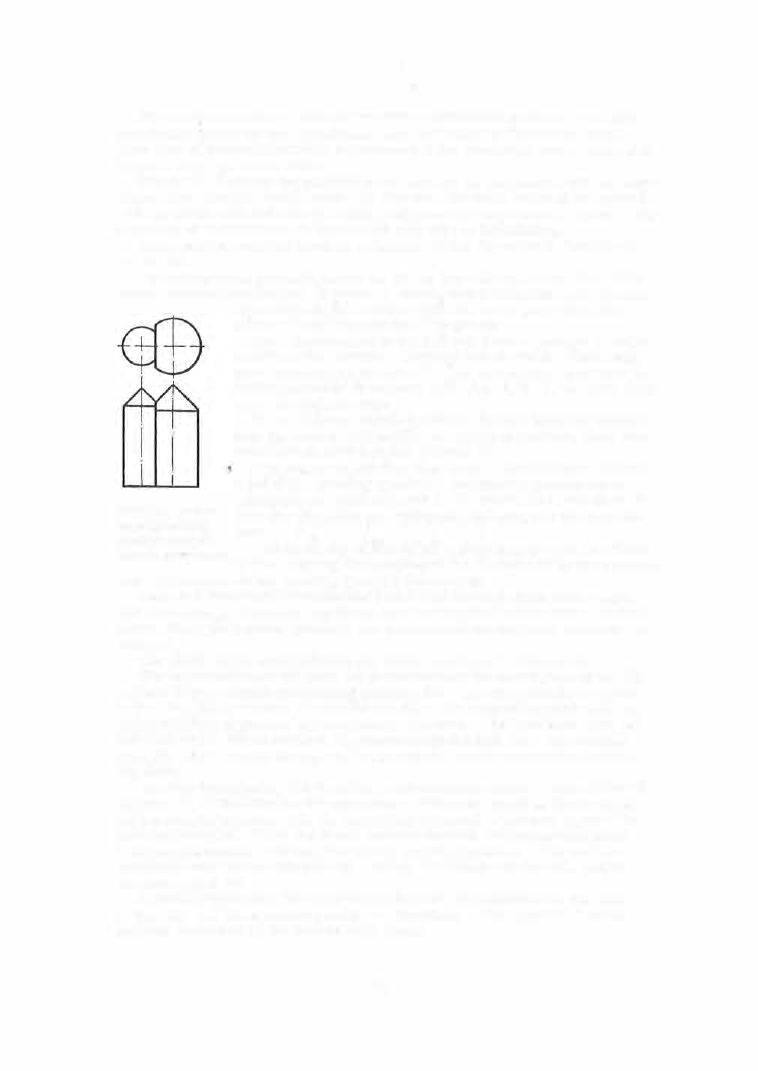
If the  distance between centers  for two holes  is  smaller 

than the s um  of the radii  of the pointing punches ,   flats  are 

machined on both punches  (Figure  4 1  ). 

The  design  of pointing dies  mus t allow for  easy replace­

ment  of the  pointing punche s .   F re quent replacement  is 

necessary  as  metal  adheres  to  the punch point and  sp reads 

FIG URE 

41. 

Mount-

over  the  cone  s urface,  dis torting the  s hape  of the indenta-

iug of the  pointing 

tions . 

punches for small dis-

tances 

be 

tween centers 

The  accuracy of  the  center punching must not be  affected 

by the  frequent  dism antling of the  die  s et  and by the  removal 

and  replacement  of  the  p ointing punches  themselve s .  

Repeated grindings o f  the pointing-punch tips  reduces  their total  length 

and it eventually becomes insufficent fo r  forming the  indentations .  In  s uch 

cases  either the pointing punches  are  replaced o r  the  die-plate  thickness  is 
reduced. 

The  most widely used pointing-die  design is  shown  in Figure  4 2 .  

The  hardened - s teel  die plate  ( 3 )  is  mounted o n  the lower shoe of the  die 

set  and  in it are fixed the pointing punches  (8 ).  The  die plate is  connected 

to the disk ( 6 ) by screws  ( 7 )  and the pin  ( 9 ) .   The  s upporting pins  ( 1 0 ),  o n  

which the  p art i s  placed,  are mounted i n  the  disk.  The  knock-out pins  (5 ), 
actuated by the  knock- out bar  (4 ),  pass through the  disk (6 ) .   The nesting 
pins  (2 ),  which locate  the  part in the  horizontal plane  are  mounted on the 

die plate. 

The  flat- faced punch  ( 1  ),  provided  with  clearance holes  to take  the  nest­

ing pins  (2 ) is  mounted in the upper s ho e .   When the  punch i s  lowered,  the 

part  des cends  together  with  the  s upporting pins  and  is  pressed against the 

pointing punches .  When  the  punch  recedes upward,  the  s upporting pins , 

being spring-loaded,  lift  the  part  off  the  pointing punches .   The  part is 

remo ved from  the nesting pins  by  a p edal,  the  knock- out bar  (4 ),  and  the 

knock- out pins  ( 5 ). 

It  might happen  that  the  longest  punches  are  concentrated  on  one  side 

of the die,  and the sho rtest punches  on the other.  The supporting pieces 

p revent dis tortion of the  part in s uch cases . 

85 

In  watch movements  the  bridges  are mounted above plates  and  the  cor­

responding holes  have the s ame  coordinates  in both parts .  A  single  die 

can therefore be  designed for p ointing the  holes  first in the plate and then, 

simultaneously,  in the  corresponding bridges .  This  increases  the  accuracy 

of hole  location  in m ating parts ,  and als o  reduces  the  number of dies  re­
quired,  althoug s uch  a  combination die is  more complex than  each of a  s et 
of separate  die s .  

FIGURE 

42 . 

Pointing  die 

Only through - holes  can  be  pointed on bridges  by means  of s uch a  die .  

Blind  holes  necessitate  a  s eparate d i e  for  each bridge.  The  accuracy of 

hole location for pointed holes  is  0 . 0 3 mm .  The  positional  accuracy obtain­

able by the  use  of drilling jigs  is  0. 05 m m .  

The  pointing process is  very productive  and the number of holes pointed 

is  limited only by the  part and pointing-punch dimensions .  The  usual  dies 

can point between  2  and  2 5  holes . 

The  shortcoming of  hole location by pointing is  that  the  drill  operator, 

using  a drill of a  given diameter,  c ould  conceivably  e rr  in his  choice  of 

pointing  marks  corresponding to the  given drill,  when faced with a  large 

number of pointing marks .  Perforated  templates (holes  0 . 0 5 - 0 . 1  mm  larger 
than the hole  to  be drilled )  are  used to  o vercome  this  disadvantage.  Each 

template is  designed for holes  of only one  diamete r .  

8 6  

Embossing and  coining*. 

These operations  are  used in  watch production 

for obtaining design  in  relief on the  back lid of watches  (Figure  43 )

for 

producing rais ed figures  and  symbols  on dials  (Figure  44 )  and fo r  other 

si'Tiilar operations . 

FIGURE 43.  Back  lid  of  a  pocket-watch 
c ase  with e mbossed  design 

FIGURE 

45. 

Wristwatch  mechanism  with 

symbols,  figures  and  inscriptions 

FIGURE 44 .  D i a l  1v ith embossed ( raised) 

figures 

FIGURE  46 .  Stamping 

depth of figures  and 
symbols 

• 

[Russian terminology  does  not  differentiate  between embossing  and  coining  dies .  As these two  terms  are 
frequently confused in  American  usage,  it  might  be  w orthwhile  to  attempt a  working definition of the 
difference betlveen the  two :  embossing  dies have  usually  the  same  design  on  the  upper  and  on  the  lower 

die,  one  being  the negative of the  other,  while  coining dies  generally  present different  designs  on  the 

upper  and  lower die ,  respectively .  A  special case  of the  embossing-type  of  die  is  the  die  used  to embellish 
the w atch  lid shmvn  in Figure 43.  Here one  die  represents  the negative of the  desired  lid surface,  while 
the  other  die  is smooth,  serving  only  as  countersupport . ]  

87 

Stamping. 

Symbols  and  figures  are  often  stamped  on  the  bridges  and 

winding wheels  of watch movements .  Stamping is  accompanied by a  local 

plastic  deformation.  Stamped ins criptions ,  figures  and  s ymbols  on  the 

movement  of a  "Pobeda "  wristwatch  are  s hown  in Figure  4 5 .   The  approxi­

mate  s tamping depth is  indicated in Figure  4 6 .  

SIVAGING 

In  s waging the  blank is  completely  contained  in  the  die under pressure 

from all sides . 

The  blanks  us ed are  of  a  s hape  approximating  that  of  the  final part, 

(cylinders ,  disks ,  etc . ).  The volum e  of the  blank is  equal  to  that of the 

FIGURE 47 . 

Pendant  of pocket 

watches 

a-blank;  b- after the first oper­

ation;  c-after  the  second  swag­
ing  operation. 

final  part  with a  s m all s urplus  which  is  required 
to  ensure that the  die  is  completely filled .  This 

s urplus  goes  into  the  formation of flash  (burrs 

at the  parting face  of the  die )  which has  to be 

removed.  The  blank for the pendant  of pocket 

watches is  obtained  by cold heading from bar stock 

and is  s hown  in Figure  47,  a ,   while  Figures  4 7 ,  
b  and  c  show the pendant  after the first and s econd 
s waging s tages  on a hydraulic pres s .  

The  blank i s  annealed  and  cleaned  after  the 

heading and  after  the  first s waging operation. 

Swaging  can be  treated as  a  kind of embossing 

or  coining,  since  the nature of thes e  processes 
is  very similar,  as  are the  working pressures 

involved  (see  Table  5 ) .  

Metals  to b e  s waged must b e  ductil e .   Ductili­

ty is  characterized by the  am ount of  deform ation 

the  metal  can  endure  without fracture.  In s wag­

ing,  the  deformation is  defined by the  relations hip 

o r  

1 00, 

where 

the  deformation in %; 

and 

H f 

the initial  and final  heights  of the blank and part,  respectively. 

and 

the  initial  and final  cross -sectional  areas  of the  blank and part, 

resp ectively. 

Embossing,  coining and  s waging operations  require  considerable p res ­

s ures  (Table  5 

)

The  force 

required  is  determined from  the  formula 

P = q · F, 

where 

q  = 

the  pressure  in  kg/mm 2 ; 

F  = 

the  part  s urface (in plane )  in  mm2 . 

88 


Content   ..  20  21  22  23   ..