Technology of watch production - part 21
 

  Index      Books     Technology of watch production (Tarasov) 1964 year


Search            


Content   ..  19  20  21  22   ..


Technology of watch production - part 21


The  m etal  is  work- hardened  during d rawing  and  the  work hardening must 

be  eliminated before  the  subsequent draw.  The parts  are  therefore  annealed 

and pickled,  after which the scale  is removed by washing. 

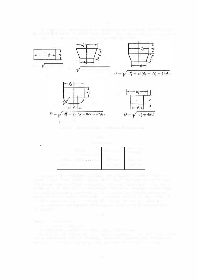
d  + 

4/t) .  

di 

+  21 

(d1 

d2). 

FIGURE  3 7 .   Calculation of blank  diameters  for  dra1"ing operations 

Material 

Brass L62 ,   tombac 

M ild  steel 

TABLE  4 

Draw  coefficients 

First  draw , 

m1 

0 .50-0 .54 

0 .52- 0.60 

Subsequent 

draws, 

m, 

0 .7 0- 0 .75 

0 .72- 0 .8 0  

Clearances between  punch  and  die. 

The m agnitude  of the  clearance be ­

tween the punch  and  the  die  depends  on  the blank  thicknes s  and  on  the  type 
of d rawing  (with  or without  a  decreas e  in the  wall  thicknes s ).  When  the 

thickness  of the  material  is  not  changed  a  clearance  somewhat l arger than 

the  s tock thicknes s  is  specified,  so  as  to  reduce  the friction between the 
s tock and  the  die  walls .  Too large  a  clearance leads  to the appearance of 

wrinkles and  too  s m all a  clearance will  lead  to  reduced  wall thickness . 

The  clearance for  the  cas e  of unchanged thickness  is  determined from 

the formula 

l = A · s, 

whe re 

coefficient; 

s tock thickness .  

is  taken  as  1 . 2 5  for 

s  < 

mm,  and  1 . 1   for s >   1 m m .  

Radii 

of 

the  die  and  punch. 

The  radii of curvature  o f  the  dies  and punches 

are  of  great importance in drawing.  Small radii produce high s tresses  and 

can lead to  tearing,  while  large  radii  may  cause  the  metal  to  wrinkle .  

8 1 

The  radius  of  curvature of  the  die  edge  for  the  firs t  draw  is  usually ten 

times  the  stock  thicknes s  for s teel and  six times  the  s tock thicknes s  for 

bras s .   In s ubsequent draws ,  the  edge  radius  is  reduced to  6 0 - 8 0  o/o  of the 
first- draw edge  radius ,  but should  not be  less  than 

3 s. 

The  punch  radii 

are  generally  equal  to the  die  radii. 

The punch radius  for the final  operation  must,  of course ,   be  equal  to 

the  desired pro duct radius . 

Lubrication. 

F riction in drawing operations ,  between punch,  stock and 

die,  is  cons iderabl e .   This  friction is  reduced by  lubricating  the  blanks 

with  engine  oil,  vas eline,  emulsions ,  or  powdered- graphite  s uspension,  etc . 

Drawing  force  and  blank-holder  pressure. 

The  drawing force is  deter­

mined from the formula 

P1 

1r:d1 · S · aunl 

for the  first operation; 

P2 

1r:d2 · S · aun2 

for  the  s econd and s ubs equent operations , 

where 

d1 ,  d2 

the  diameters  of the  drawn part  after  the  first  and  s econd 

operations ,  respectively; 

n1 ,  n2 

correction factors  depending  on  the  ratio 

The  values of 

n1 

and 

n2 

are usually between  0 . 6  and  0 . 8 .  

The  blank - holder forc e  i s  determined from  the  formula 

qF, 

where  Q 

the holding force,  kg; 

= the  blank- holder pressure,  kg/mm 2 ; 

the  blank-holder area,  mm 2 . 

If  the  holding force is  insufficient,  wrinkles  are formed on  the blanks . 

If  it  is  too  large,  the  blank m ay  tear . 

FIGURE 

38 .  Combination  blanking­

drawing  die 

The  value  of 

can  be  taken  as  0. 1 5  to  0 . 2 0 kg/mm 2  for bras s ,   and 

0 . 2 0 - 0 . 3 0 kg/mm2  for s teel .  The  total  press  force  is 

82 

Drawing  dies  are  clas sified,  according  to  the  operations  they perform, 

as first - draw  dies ,  or dies for s econd,  or s ubsequent draws . 

Firs t - draw  dies  can  be  either s imple  or  combination  die s .   A  simple  die 

draws  a  previously punched blank.  A  c ombination  die  (Figure  3 8 )  performs 

both blanking  and  first- drawing operations . 

The  die  can  operate  on a  s ingle - action press .  The  blanking punch,  a 

hole in which  s e rves  as  a  drawing  die ,  is  fastened  to  the  upper sho e .   The 

blanking die and the  drawing punch are mounted on the  lower  shoe.  The 

die  is p rovided with  a  rubber  cushion for stripping and  ejecting the  part. 

STRAIGH�ENING,  POINTING ( CENTER  PUNCHING), EMBOSSING ,  STAMPING 

Straightening. 

Parts  obtained from  a  blanking operation are  usually not 

completely flat.  Such parts  can be flattened and  smoothed by s queezing 
them between the punch  and  die  s urfaces  of a  die  s et.  If the  s urfaces  of 

the punch and  die  are  s mooth,  the process is called s m o o t h  straightening. 

If  angular slots  are  milled  on the  punch  and  die  s urfaces  in two  mutually 

perpendicular  direction,  (knurling)  pyramids  with  sharp  apices  result. 

A  part s traightened on s uch a  die  bears  imprints  on its  surface and this 

process  is  called  p o i n t   straightening. 

The  apices 

the  punch pyramids  do not necess arily  coincide  with those 

of  the  die pyramids .  Point straightening gives  better  results  than  does 

smooth  s traightening,  and a part subjected to point straightening does  not 

s how elastic  spring-back  If the  apices  of the  punch  and  die  pyramids  are 

blunted,  the  depression pattern  formed on the  surface of the  s traightened 

part is  of the  s o - called w a f e r   type  and  is  us ed for  thick parts  made  of 
s oft metals . 

A  die used in  the point straightening of alarm - clock plates  is  shown in 

Figure  3 9 .   Since  straightening imprints  are not allowed around  the  holes 

in this part,  the pyramidal  apices have been removed near the holes .  The 

alarm - clock plate  is  positioned for straightening by means  of pins  matching 

the  holes  in the plate. 

Pointing  (center punching). 

A  pointing  die  consists  of flat  punch and die 

plates  with hardened- steel  points p ressed into the  die and  protruding above 
its  s urface .  

The  blank is  located i n  a  nest  which is  either fastened t o  the  d i e  or set 

on pins  mounted  on the  die .  

When the  upper shoe o f  the  die  s et  is  lowered,  the lower face o f  the 

punch pres s es  the blank against the  upper die  face,  and the p oints  penetrate 

into  the  metal  and  indent it.  These  indentations  s erve  for  guiding  the 

drill in s ubsequent operations . 

In order to  reduce  the  adherence  of m etal  to  the  points ,  they must have 

a  s moothly polished s urface .   The  indentation  diameter mus t  be larger than 
the  drill  diameter,  and the  angle  of the  indenting point  must  be smalle r  than 

the  drill -point  angle. 

The position of the  drill  in the  indentation as a  function of the  point angle 

and  punching  depth is  s hown in Figure  4 0 .  

Figure  40, a  shows  the  position  of the  drill i n  a n  indentation  of a  diameter 

smaller than the  drill  diameter.  The point angle  is  8 0°  and the drill-point 

83 

angle  is  about  1 2 0° .   Touching,  initially,  only  the  rim  of  the  pointing crater , 

the  drill  is  poorly  guided.  Figure  4 0 ,  b  shows  the  position  of  the  drill  in 

an  indentation  of  a  diameter larger than  the  drill  diameter.  The  point angle 
is  8 0°,  and  the  drill -point  angle  is  about  1 2 0° .   The  displaced metal  is  not 

removed in the s ubsequent  drilling.  In this  cas e ,   the drill  is better guided 

and,  if p rope rly  ground,  will pro duce accurate  holes,  both from  the dimen­

sional and the positional  point  of view. 

FIGURE 

3 9 .   Die 

for  poi nt··strai ghtening  alarm­

clock plates 

FIGURE  40. 

Position of the  drill 

in 

the  pointing 

indentation 

for  different 

punching  depths 

84 


Content   ..  19  20  21  22   ..