Technology of watch production - part 20
 

  Index      Books     Technology of watch production (Tarasov) 1964 year


Search            


Content   ..  18  19  20  21   ..


Technology of watch production - part 20


A  shortcoming of  these dies  is  that  the  whole  s et  has  to  be  dismantled 

for  regrinding.  In other models  the  dies  and punches  are  ground  in  the 

shoes .  Generally,  s tandard  crank presses  are  us ed  for  shaving operations . 
P recision parts ,  in  particular springs  of  the  type  shown  in  Figure  1 0,  are 

sha ved  on vibration presses . 

Bending. 

When a  part  is  bent,  the  external  fibers  of  the  metal  are 

s tretched and,  if the bending  radius  is  small  and the  part  thickness  large , 

failure  occurs  in  the  external  fibers . 

The  values  of  the  smallest bendin g  radius  permissible  depends  on  the 

properties  of the  m etal,  the  strip  thickness  and the  relative  directions  of 

the  axis  of the  bend  and the  grain.  The value of 

is  determined from  the 

formula 

r = k · s, 

where 

=  s trip  thicknes s ,   mm; 

=  a  factor depending o n  the material ,  and having the  following 

values for various  metals : 

Soft  brass 

Semihard 

Soft  steel 

Semihard 

Stainless 

Material 

brass 

steel 

steel 

0 .25 

0 . 35 

0 . 35 

0.6 

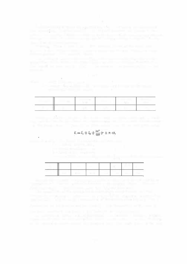
A s suming that  the  length  of  the  neutral  axis  remains  unchanged  in  bend-

ing,  and that the inside fibers  are  compres s ed  and the outside fibers  extend­

ed,  the  blank length  (Figure  3 1 )  is  determined from the  following fo rmula: 

where 

lt 

and 

[2 

= lengths  of  the  straight  sections ,  mm; 

=  bending radius ,  mm; 

= stock thickne s s ,  mm; 

ct 

=  bend angle,  degrees ;  

= a  coefficient depending on ratio  !:..,having the following values : 

-

0 . 1  

0 .25 

0 .5 

0 .18 

0 .26 

0 . 33 

0 .39 

0 .44 

0 .47 

0 . 50 

Elastic  deformation is  always  present in  bending,  and  the  part tends  to 

"spring back" ,  that  is ,  partially  returns  to  its  original  s hape .  The  actual 

final  bend angle  is  therefore  smaller  than  the  die  bend  angle . 

The  magnitude  of  the  spring-back  depends  on  many  factors  and it is 

frequently necessary to  determine  the  punch  and  die  angles  of  bending dies 

empirically.  Figure  32  is  a  nomogram  of  the  spring-back angle 

f. 

ct 

as  a 

function  of  the  bend angle a nd  the  ratio !.._,  The  dispos ition  of  the  axis  of 

the  bend relative to  the  grain  of  the  material  is  very important . 

A s  mentioned  earlier,  rolled  materials ,  i . e .   m aterials  having a  definite 

direction of  grain,  s hould not be bent about  an axis  parallel  to  this  direction 

as the extended outside fibe rs  are  liable  to  fail.  The  angle between the axis 

7 7  

FIGURE 31. 

Bent  plate 

FIGURE 

32.  Dependence  of the  spring-back 

<lc< 

orr the ratio  ¢ 

FIGURE 

3 3 .   Bending die 

7 8  

of  bending  and  the  direction  of  the  grain  should  therefore  preferably be  9 0°, 

but shoul d

not be  reduced  below  30°. 

Bending dies are  relatively  simple in design.  The  shapes  of the punches 

and  dies  correspond  to  that  of the part to  be  bent ,  allowing fo r  spring- back . 
Open- type  dies  are  used for simple  bending operations ,  while  more complex 

operations  are  performed on dies  provided  with  knock- outs  and special 

blank  holders . 

The  design  of  a  bending die  for  alarm - clock  detents  is  shown  in  Figure 3 3 .  

Both  ends o f  the  detent are  bent  simultaneously.  The  die  (6 )  with  the  guide 

pins  (4 )  and  ( 5 )  is  mounted  on the  support ( 7 ) .   The  support can  move  with 

the  slide  (8 )  in  the  base  (9 ).  The punch  (2 )  and  the p ressure pad  ( 3 )  are 

fastened  to the shank  ( 1 )

When the p ress  ram  descends ,  the pad  ( 3 )  presses 

the  part  against the die fac e .   As the punch  (2 )  continues  to descend,  the 

right-hand  end  of' the  detent is  bent by  1 05°.  The  bending  radius 

is  about 

2 . 5  mm,  or 

4 s. 

DRAWING 

Hollow parts  are  d rawn  from  flat blanks  on single- action o r  doubl e - action 

pres ses . 

Drawing  can  be  defined  as  a  process  in  which  a  punch  forces  a  flat blank 

into  a  die  hole  and  caus es  it to  assume  the  shape  of the punch  (Figure  34 ). 

FIG UI<E  34 .  Schematic  dia­
gram of the  dra1ving process 

1 - punch;  2 -die;  3-blank. 

FIGURE  35  Schematic  di agram  of 
dra�;ing  '''ith  a  blank  holder 

1 - punch;  2- die;  3-blank  holder. 

1

Drawing  operations  are  o f  two  types :  1 )   drawing without  changing  the 

initial  s tock thicknes s   (the  thickness  of  the  walls  and  of  the  bottom  of  the 
product  are  equal  to  the  blank  thicknes s );  2 )   drawing with  a  reduction in 

the  s tock thickness  (the  wall thicknes s  of  the  product is  smaller than  the 

blank thicknes s ).  If the  difference between  the  diameter of the p roduct and 

that of the blank is  s m all ,  drawing is  performed without using  a blank holder . 

If  the  difference in  diameters  is  considerable,  a  blank  holder  is  us ed  (Fig­

ure  3 5 ),  as  otherwise  wrinkles  m ay form  (Figure  3 4 ) .   A  blank holder is 

us ed in  all  cases  where  the  blank thicknes s  does  not  exceed  1 / 7 0  of its  dia­

mete r .  

I f  

the  thickness  of the  blank i s  larger than  1 / 5  0  o f  its  diameter,  a 

7 9  

blank holder  is  not necessary.  If  the  thickness  is  s omewhere  in  between , 

either s ystem can  be  us ed.  The  press  force  required increases  when  a 

blank holder  is  used. 

Deep  shells  are drawn  in two,  three or more s tages  with intermediate 

annealings  to  eliminate  the  work- hardening effect.  Alarm - clock cases  and 

air- and  s eaborne watch cases  are  examples  of drawn watch parts . 

Blank 

dimensions . 

Drawing  does  not change  the  volume  of  the  metal . 

If  the  wall  thicknes s   of  the  drawn p roduct is  the  same as  that of the  blank, 

FIGURE  36 .  Development  of 
a  hollow  cylinder : 

1 -blank;  2 -product;  3-de-

velopment . 

the  blank area 

F1 

will  be  equal  to  the  surface  area 

Fz of the  drawn p roduct.  If the  height of the pro duct 

does not  exceed  half  its  diameter and its  wall  is 

not larger than  1 mm, 

F2 

will be the  external  sur­

face  of the p roduct':' . 

The  diameter 

of  the  circular blank from  which 

a  hollow  cylinder  of height  h  and  diameter 

(Fig­

ure  3 6 )  is  to be drawn  is  found from the relation-

.  "D2 

"d2 

.  D 

s h1p 

1t

d

h;  we  obtam: 

+  h). 

An  allowance  of  3  to  5 o/o  is  added  for  trimming 

the  edges  which,  after drawing,  will  be une ven. 

When a  complex part is  drawn in s everal stages , 

the  dim ensions  of  the  blank are  either computed or 

experimentally  determined .  

Figure  3 7  gives  the formulas  for calculating the 

blank  diameter for  various  drawn  shapes. 

Number of  stages  i n  drawing. 

Deep  s hells  cannot 

be pro duced in one  s ingle  draw from  a  flat blank as 

the  extensive  deformation involved  would  caus e  a 

failure.  Deep  shells  are therefore  drawn in several 

s tages ,  the  depth being increas ed in  each s tage . 

for each  draw  is 

The ratio of  product diam eter  to blank diam eter 

expressed as  the  draw coefficient: 

where 

the blank diam eter; 

m1,  m2 ,  m,. 

draw  coefficients; 

d,. 

m,. = d,.-1 ' 

d1,  d2 ,  d,._1 

diameters  obtained  in the  successive  draws; 

d,. 

diam eter  of  the  final  p roduct. 

The draw coefficient 

depends  on the technological properties  of the 

material  as  determined by the  Erichsen test,  on its  surface  condition  and 

thickness,  on the  drawing method us ed  (with  or  without  a  blank  holder),  on 
the pro duct  s hape,  etc . 

Empirical  average  values  of  draw coefficients  for cylindrical products 

are  given in Table 4 .  

The  higher  values  given i n  each cas e  s hould b e  used f o r  s tock not thicker 

than  1 . 5 mm  and  drawn  at high  speed  while the lower values are meant for 

thicke r  s tock,  drawn at  lower  speeds . 

• 

For  dra\v ing  irregularly  shaped  products  of complex shape,  the  calculations  given  in 

V .  P .  

Romanovskii's 

book  " Spravochnik  po  l<holodnoi  shtampovke" ( Handbook ofCold Stamping)  Mashgiz, 

1954, 

will be  useful. 

80 


Content   ..  18  19  20  21   ..