Technology of watch production - part 5
 

  Index      Books     Technology of watch production (Tarasov) 1964 year


Search            


Content   ..  3  4  5  6   ..


Technology of watch production - part 5


REFERENCE  SURFACES 

Parts  which  are  to  be  processed on  a  machine  mus t  be  positioned  rela ­

tive  to  the  cutting tools  and  must then be  held  in pos ition by  clamping de­
vic es . 

Selection of  the  reference  s urfaces  during  the  part-design  s tage  deter­

mines  how the part will  be  dim ens ioned.  Depending upon the reference 

surfaces  s elected,  a  means  for positioning and fastening the parts  for ma­

chining is  adopted,  and this  in turn  determines  the  basic  design  of the 

clamping device .  

The  reference  s urfaces  also  determine  the  pos ition o f  the part i n  the 

as s embled product and its  interconnection with the  other  parts : 

Thus ,  the  concept  of  "reference  s urface "  denotes  the  totality  of  surfaces , 

lines  or  points  in  elation to  which are  orientated those  surfaces  which ad-

join  (in  the  finished product) other c omponents 

or thos e  s urfaces  of a  c omponent  which  are 

machined at the  given s tage of manufacturing 

of said  components . 

We  distinguish between m a i n   r e f e r e n c e  

s u r f a c e s ,  g u i d e   s u r f a c e s ,  a n d  s t o p  

s u r f a c e s . 

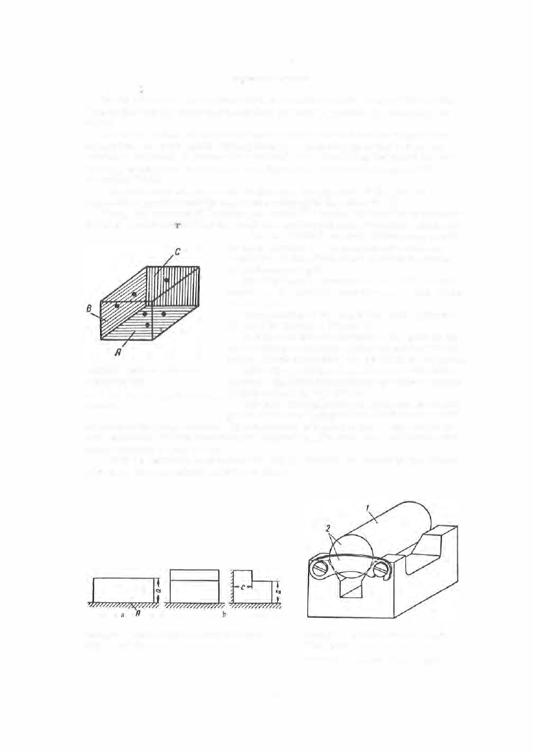
The  pos ition  of  these s urfaces  in a  prisma­

tic part is  shown  in Figure  9 .  

In  o rder to  direct  (orientate) the part o n  the 

main reference surface we have to set it on three 

points  which  determine  the  position of  the  plane . 

After the  part is  s et  on  the  main  referenc e 

surface,  its  orientation  along the  guide  surfac e  

A-maln reference ;  B-guide;  e-stop 

is  determined by  two  points . 

The part  having been s et  along the  main  and 

FIGURE 

9 .  

Reference surfaces on 

a  prismatic  part : 

surfaces. 

guide  s urface s ,   one  point  suffices  to  fix  it with 

respect to  the  stop  s urface.  If orientation  of a  part in  three  directions  is 
not neces sary  during ass embly or  machining,  the  number of  reference  sur­

faces  reduces  to  two  o r  one . 

Let it be  required to  machine  the  upper s urface  and  maintain  the  dimen­

s ion a  on the part shown in Figure  10, a .  

FIGURE 

1 0 .  

Machining parts  according to  different 

holding  surfaces 

1 7  

FIGURE 

1 1 .  

Reference  surfaces  of a  cylin­

drical  part : 

1 -double  guide  surface;  2-stop surface. 

In  this  case  the  part to  be  machined  is  s et  on  the  main  reference  sur ­

face A ,   while  the  guide  and  stop  surfaces  a r e  of n o  special  importanc e .  

If,  o n  the  other hand,  w e  are  required t o  machine  the  dim ensions  a  and 

c  (Figure  1 0 ,  b ),  we  s et  the  part along the  main and  the  guide  reference 

surfaces,  the stop  surface  be ing  of no  spec ial  importance. 

In thes e  examples  the  c oncept  of  " refe rence surface "  includes  one o r  

two  surfaces  of the  part,  respectively . 

The  position  of  cylindrical  parts ,  such as  rolle rs  o r  shafts ,  is  deter­

mined by the position of the axis  of the external  cylindrical  s urface in  the 

horizontal  and  ve rtical  directions ,  and  by  the  pos ition  of  an  end  surface. 

It is sufficient to support cylindrical  parts  on  four points  of  the  external 

cylindrical  surface and  on  the  end,  as  s hown in Figure  1 1 .  

A  cylindrical  surface  along which the  p art  is  s et  as in  Figure  1 1  is  called 

a  d o u b l e   g u i d e   s u r f a c e . 

T h e   s t o p   s u r f a c e   in  this  case is Jhe  cylinder  end. 

Let it be  required  to  turn  a  shoulder on a  cylindrical blank (Figure  12 ). 

When the blank is  clamped,  the cylindrical  surface of the  c ollet serves 

simultaneously as  main  referenc e ,   guide and stop  surface  for obtaining the 

dim ension 2 . s - 0 . 02m m .   The  cylindrical  surface of the  collet als o  serves 

as  the  guide  surface for  obtaining the  dimension  8 . 5 - 0 . 1 0 ,  while  the  in­

ternal  shoulder  of the collet serves  as  both the main reference surface  and 

the  stop  surface .  

FIGURE  12.  A  cylindrical part  held in  a  collet 

Surfaces  are  class ified,  according to  their function,  as  being either 

d e s i g n ,   a s s e m b l y ,   h o l d i n g   o r   m e a s u r i n g   s u r f a c e s . 

T h e   d e s i g n   s u r f a c e s   of  the  part are  the  totality  of  surfaces ,  lines 

or points  relative  to which the other parts  of the product are  o rientated in 

the  designe r ' s  calculations . 

A n   a s s e m  b 

y  s u r f a c e   is  the  totality  of  surface s ,   lines  or  points 

relative  to  which the  other parts  of  the  product  are  actually  o rientated .  

A  h o l d i n g   ( t e c h n o l o g i c a l )  s u r f a c e   is the totality of s urface s ,  

lines  or points  relative t o  which  a  surface being machined i s  orientated 

during the  manufacture  of the  part. 

A  m e  a s  u r i  n g  s u r f a c e   is  that  surface  (or  s et  of surfaces )  from 

which the  dimensions  are  measured . 

Parts  processed  on  machines  are  set and  held in universal  o r  special 

clamping  (fastening )  ':!evices . 

1 8  

Since  all  the  parts  of  a  type  are located  on the  same surface in  the  same 

manner,  and are machined identically,  their  dimensions  will  be  identical 

within the process  accuracy. 

When working with l ocating fixtures ,  l o c a t  i n  g  e r r o r s  appear in 

addition to the  random  errors  described  earlier. 

FIGURE 

13.  Locating  error for  different holding surfaces 

The  following example will  s erve  to  illustrate  how  the  s election  of  the 

holding surface influences  the  machining accuracy  and  the  design  of  the 

fixtures . 

Example,  It  is required that  the  dimension 

1 .2-0.010  be held  in machining the watch plate shown in 

Figure 

13,  a.  This is achieved  directly by  means of the  setup shown in Figure 13, a,  where  the  dimension 

1 .2_ 0.010 is measured from  the holding plane 

B. 

The  variation 

in 

the  dimension 

1.2  in the  parts will depend 

only on random factors causing scatter in the  dimensions. 

In Figure 

13, b,  it is required to hold the  dimension 0.80+ 0.01,  measured not from the  holding  plane 

B, 

but from  the  plane  A .  

I f  the pan  is set o n  plane 

B, 

the  dimension 

0.8 will depend both on random factors an<i o n  the  actual 

magnitude  of the dimension 

2 mm which has been machined previously.  In this case the dimension 0.8  will 

have deviations of a magnitude of 

0.01 +  0.02 

0.03 mm.  In order to increase the accuracy,  the tolerance 

for the  dimension 

2.0 mm would have  to be  narrowed.  This,  however,  would render the machining more 

complex  and  cost! y. 

The  best solution  in  the given  case  is to set the  part  on plane  A .  

This  example  shows  that,  all  other conditions  being equal ,  the  highest 

accuracy  is  achieved when the plane from which the dimension in question 

is  m easured  is  the holding surface,  that is  when the  m e  a s  u r i  n g  and the 

h o l d i n g   s u r f a c e s  coincide. 

1 9  

Technolo gical processes  are  accordingly preferably  designed s o  that 

the  reference  and  design  surfaces  coincide .  It is  also  des irable  to  use  the 
same s urface for as  many  operations  as  pos sibl e .   The  transition from  one 

surface  to  another is  always  bound up with suppleme ntary  errors .  The 

selection of the holding surfaces  must not only ensure  the  required machin­

ing accuracy,  but  must als o  allow the  reliable fastening of the  part  in the 

fixture. 

The calculation of the  locating  error  as  a  function o f  the l ocating m ethod 

for  different cases  is  given in the  specialized literature .  

A LLOWANCES  A ND  INTEROPERATIONAL  TOLERANCES 

The  metal layer which must be  removed in an  operation  or  suboperation 

in order to  obtain  the  specified dimension is  called  the a 

1 1  

o w  a n  c e  f o r  

t h e   g i v e n   o p e r a t i o n   o r   p a s s . 

The  value  of  the  allowances  specified depends  both  on  the  method used 

to make the premachined blanks and on the  machining process in question.  The 

more accurate  the  blank,  the  smaller the  machining allowance  required. 

Larger allowances  are  allowed for roughing operations  than for finishing 

operations . 

The  question  of  the  magnitude  of  machining allowances  is  of  great tech­

nical and economical  importance because the metal  removed by machining 

is  as  good  as  lost,  s ince the  value  of s havings  is  much  smalle r  than  that 

of the  o riginal  metal  stock. 

In addition,  the removal  of an exces s ively large allowance  requires  time ,  

thus  lowering the  productivity and  the  capacity  of the  equipment,  and  raising 

tool- wear and  power -expenditure  rates .  

Excessively large  allowances  are  thus  s een t o  reduce  the  economic  ef� 

fectivenes s  of the process .  

Excessively small  allowances  are not desirable  either,  since  they make 

the  s etting and  adjustm ent  of the parts  on the machines  more  difficult and 

require  higher accuracy in  the blanking operations ,  increasing their cost. 

Machining allowances  specified must therefore be as  s mall as is  poss ible 

under the  given process  conditions . 

Long production  experience  has made it possible to fix ave rage allowances 

for blanks  obtained by various  methods  or being prepared for various  ma­

chining p rocesses  and  thes e  can be found in the handbooks  or factory spe­

cifications ,  o r  can be  calculated . 

The  allowances  for machining  external  and  internal  cylindrical surfaces 

are  given  on the diameter  (for both side s ).  The allowances  on external 

planes  and  end  surfaces  are  given for  one  s ide;  and  their num erical  values 

are  accordingly half  as large as thos e  for  corresponding cylindrical surfaces .  

The  total  allowance for the  machining of  a  surface i s  the  sum  o f  the al ­

lowances  for all  the  various  operations . 

In  order to  ensure  that  one  operation  will  not  remove  the  minimum  al ­

l owance  intended for  the  next operation,  o p e r a t i o n a l   t o l e r a n c e s   a r e  

s et  on  the  nominal  value  of  the  allowance for each  operation,  and  thus  the 
maximum  and  minimum  values  for  each  operational  allowance  are  fixed. 

20 


Content   ..  3  4  5  6   ..