DB2 Server for VSE System Administration (Version 7 Release 5) - page 7
***********************************************************************
* RETURN TO CALLER
***********************************************************************
RETURN
DS
0H
RETURN POINT
L
R2,RETPTR
LOAD RETCODE PTR
ST
R15,0(R2)
STORE EXIT RETURN CODE
L
R14,12(,R13)
RESTORE R14
LM
R0,R12,20(R13)
RESTORE REST OF CALLER’S REGS
BR
R14
RETURN TO CALLER
EJECT
PARMLIST DSECT
,
INPUT PARAMETER LIST
EYECATCH DS
CL8
EYECATCHER
PLEN
DS
F
LENGTH OF PARAMETER LIST
FNPTR
DS
AL4
POINTER TO FUNCTION TYPE
FNLENP
DS
AL4
LENGTH OF FUNCTION TYPE
GLBPTR
DS
AL4
POINTER TO GLOBAL EXIT AREA
GLBLENP
DS
AL4
LENGTH OF GLOBAL EXIT AREA
ISOPTR
DS
AL4
POINTER TO ISO DATETIME AREA
ISOLENP
DS
AL4
LENGTH OF ISO DATETIME AREA
LOCPTR
DS
AL4
POINTER TO LOCAL DATETIME AREA
LOCLENP
DS
AL4
LENGTH OF LOCAL DATETIME AREA
WORKPTR
DS
AL4
POINTER TO USER WORK AREA
WORKLENP DS
AL4
LENGTH OF USER WORK AREA
ENVPTR
DS
AL4
POINTER TO ENVIR. DEPENDANT AREA
ENVLENP
DS
AL4
LENGTH OF ENVIR. DEPENDANT AREA
RETPTR
DS
AL4
POINTER TO RETURN CODE AREA
RETLENP
DS
AL4
LENGTH OF RETURN CODE AREA
EJECT
ARIUXDT
CSECT
,
R0
EQU
00
EQUATES FOR REGISTERS 0-15
R1
EQU
01
R2
EQU
02
R3
EQU
03
R4
EQU
04
R5
EQU
05
R6
EQU
06
R7
EQU
07
R8
EQU
08
R9
EQU
09
R10
EQU
10
R11
EQU
11
R12
EQU
12
R13
EQU
13
R14
EQU
14
R15
EQU
15
END
ARIUXDT
Figure 109. IBM-Supplied Version of ARIUXDT (Part 2 of 2)
Figure 110 on page 282 shows the IBM-supplied ARIUXTM module. This module is
an A-type source member named ARIUXTM. You can modify this source code to
support your local time format requirements.
Chapter 13. Creating Installation Exits
281
TITLE ’ ARIUXTM’
***********************************************************************
* ARIUXTM USER TIME CONVERSION ROUTINE
REGISTER ASSUMPTIONS:
R1
-> PARMLIST
R13 -> SAVE AREA
R14 -> RETURN ADDRESS
R15 -> ENTRY POINT
* ALTHOUGH PROVIDED IN A GENERAL INTERFACE LIBRARY, ARIUXIT IS NOT TO *
* BE USED AS A GENERAL PROGRAMMING INTERFACE. REFER TO PRODUCT
* DOCUMENTATION TO DETERMINE INTENDED USAGE.
***********************************************************************
ARIUXTM CSECT ,
ARIUXTM AMODE 31
ARIUXTM RMODE ANY
USING *,R15
ESTABLISH TEMP ADDRESSABILITY
B
PROLOG
BRANCH TO START OF PROGRAM
DC
C’ARIUXTM’
DROP
R15
DROP R15 AND USE OWN ADDRESSABIL-
ITY
PROLOG STM R14,R12,12(R13)
SAVE REGS IN CALLER’S AREA
LR
R12,R15
SAVE BASE REGISTER
PSTART EQU ARIUXTM
START OF PROGRAM
USING PSTART,R12
SET UP BASE REGISTER
L
R1,0(R1)
POINT TO PARAMETER LIST
USING PARMLIST,R1
ADDRESSABILITY FOR INPUT PARMS
L
R2,FNPTR
POINT TO FUNCTION TYPE
***********************************************************************
* M A I N L I N E
***********************************************************************
MAINLINE DS
0H
START OF CODE
SPACE
SR
R15,R15
INITIALIZE RETURN CODE TO ZERO
***********************************************************************
* HERE YOU WOULD PLACE CODE THAT GETS AND VERIFIES YOUR
* INPUT TIME AND CONVERTS IT TO EITHER TO LOCAL FORMAT OR ISO FORMAT
* A RETURN CODE OF -1 MEANS AN EXIT IS NOT PROVIDED
* A RETURN CODE OF 0 MEANS CONVERSION WAS SUCCESSFUL
* A RETURN CODE OF 4 MEANS THAT THE TIME VALUE WAS OUT OF RANGE
* A RETURN CODE OF 8 MEANS THAT THE TIME WAS INVALID
***********************************************************************
BCTR R15,R0
EXIT NOT PROVIDED
B
RETURN
CONVERSION COMPLETE
Figure 110. IBM-Supplied Version of ARIUXTM (Part 1 of 2)
282
System Administration
***********************************************************************
* RETURN TO CALLER
***********************************************************************
RETURN
DS
0H
RETURN POINT
L
R2,RETPTR
LOAD RETCODE PTR
ST
R15,0(R2)
STORE EXIT RETURN CODE
L
R14,12(,R13)
RESTORE R14
LM
R0,R12,20(R13)
RESTORE REST OF CALLER’S REGS
BR
R14
RETURN TO CALLER
EJECT
PARMLIST DSECT
,
INPUT PARAMETER LIST
EYECATCH DS
CL8
EYECATCHER
PLEN
DS
F
LENGTH OF PARAMETER LIST
FNPTR
DS
AL4
POINTER TO FUNCTION TYPE
FNLENP
DS
AL4
LENGTH OF FUNCTION TYPE
GLBPTR
DS
AL4
POINTER TO GLOBAL EXIT AREA
GLBLENP
DS
AL4
LENGTH OF GLOBAL EXIT AREA
ISOPTR
DS
AL4
POINTER TO ISO DATETIME AREA
ISOLENP
DS
AL4
LENGTH OF ISO DATETIME AREA
LOCPTR
DS
AL4
POINTER TO LOCAL DATETIME AREA
LOCLENP
DS
AL4
LENGTH OF LOCAL DATETIME AREA
WORKPTR
DS
AL4
POINTER TO USER WORK AREA
WORLENP
DS
AL4
LENGTH OF USER WORK AREA
ENVPTR
DS
AL4
POINTER TO ENVIR. DEPENDANT AREA
ENVLENP
DS
AL4
LENGTH OF ENVIR. DEPENDANT AREA
RETPTR
DS
AL4
POINTER TO RETURN CODE AREA
RETLENP
DS
AL4
LENGTH OF RETURN CODE AREA
EJECT
ARIUXTM
CSECT
,
R0
EQU
00
EQUATES FOR REGISTERS 0-15
R1
EQU
01
R2
EQU
02
R3
EQU
03
R4
EQU
04
R5
EQU
05
R6
EQU
06
R7
EQU
07
R8
EQU
08
R9
EQU
09
R10
EQU
10
R11
EQU
11
R12
EQU
12
R13
EQU
13
R14
EQU
14
R15
EQU
15
END
ARIUXTM
Figure 110. IBM-Supplied Version of ARIUXTM (Part 2 of 2)
After the program is coded, assemble it as you would any other program.
Installing Your Version of ARIUXDT or ARIUXTM
After assembling your program, you must catalog the ARIUXDT TEXT (or
ARIUXTM TEXT) file into your private sublibrary. (Your assembled version of
ARIUXDT or ARIUXTM must be named ARIUXDT TEXT or ARIUXTM TEXT.)
Then link-edit the exit router component ARIXSXR.
The ARIXSXR component contains the IBM-supplied version of ARIUXDT (or
ARIUXTM). The link book name is ARISLKXD. When doing the link-edit, specify
your private sublibrary ahead of the DB2 Server for VSE sublibrary on the LIBDEF
statement that defines the search order. The link-edit will then replace the
IBM-supplied version with your version.
Chapter 13. Creating Installation Exits
283
An example of job control to install a user version of ARIUXDT or ARIUXTM is
shown in Figure 111. Here, it is assumed that the ARIUXDT OBJ (or ARIUXTM
OBJ) file is in a sublibrary called LIB.USER, and the ARIXSXR component will be
replaced in PRD2.DB2730.
// JOB INSTALL USER
// LIBDEF *,SEARCH=(LIB.USER,PRD2.DB2730),CATALOG=PRD2.DB2730
* ****************************************************************
* INSTALL ARIUXIT USER EXIT ROUTINE
* ****************************************************************
// OPTION CATAL
INCLUDE ARISLKXD
// EXEC LNKEDT,PARM=’MSHP’
/*
/&
Figure 111. Example Job Control to Install ARIUXDT or ARIUXTM
Updating the SYSTEM.SYSOPTIONS Catalog Table
You need to update the SYSTEM.SYSOPTIONS catalog table to specify the length
of your local datetime format.
If you installed a local date or time format, you can update the local date or time
length by using the database manager. For example, if the length of your local date
format is 10 bytes, enter:
UPDATE SYSTEM.SYSOPTIONS -
SET VALUE = ’10’ -
WHERE SQLOPTION = ’LDATELEN’
The local date length specified must be greater than 9 and less than 255.
If the length of your local time format is 8 bytes, enter:
UPDATE SYSTEM.SYSOPTIONS -
SET VALUE = ’8’ -
WHERE SQLOPTION = ’LTIMELEN’
The local time length specified must be greater than 7 and less than 255.
The changes will be in effect the next time the application server is started.
You can also update the SYSTEM.SYSOPTIONS table by modifying the
IBM-supplied ARISDTM member to specify your datetime defaults, then call the
DBS utility, specifying the ARISDTM member as the control file.
Coding Your Own TRANSPROC Exit
General-Use Programming Interface
The TRANSPROC exit is a General-Use programming interface. General-Use
programming interface is defined in “Programming Interface Information” on page
425.
284
System Administration
The TRANSPROC exit is used for DBCS conversion. The database manager
converts DBCS characters from one DBCS CCSID to another by using the value
specified in the TRANSPROC column of the SYSTEM.SYSSTRINGS catalog table.
This conversion can be performed when the CCSID of the source and the target are
both mixed or are both graphic; that is, the TRANSTYPE column of
SYSTEM.SYSSTRINGS has a value of 'PM', 'MM', or 'GG'.
The TRANSPROC exit is also used
v for EUC conversion, to convert MBCS data to mixed data. In EUC conversions,
the TRANSTYPE column is either 'PM', or 'GG'.
v to convert Unicode data to CCSIDs that are supported on the database manager.
For Unicode to host conversions, the TRANSTYPE column is one of 'US', 'UM'
'UG', or 'UI'.
If you have created your own DBCS CCSIDs, you must create your own
conversion routine. To do so:
1. Compile, link-edit and GENMOD your routine to create a MODULE file, and
store the module on the production disk.
2. Insert the name of the phase in the TRANSPROC column of the row for which
you want either mixed-to-mixed or graphic-to-graphic conversion. (For
example, you could create and run a DBSU job to perform this task.)
3. Stop the application server.
4. Run the job control program ARISCNVD to regenerate the CCSID-related
phases. See the DB2 Server for VSE Program Directory manual for more
information on the job control program ARISCNVD.
5. Restart the application server.
The interface between the database manager and a DBCS conversion routine
supplied by a user must conform to the following:
v Register conventions:
- Register 0 is undefined.
- Register 1 contains the address of the control block that contains the
parameters.
- Registers 2—12 are undefined.
- Register 13 contains the address of a standard register save area.
- Register 14 contains the return address.
- Register 15 contains the address of the user routine.
Registers 2 to 13 must be saved and restored by the routine. If this is not done,
the results are unpredictable.
v Parameter list, which is in the following form:
- Address of the data to be converted (4 bytes)
- Address of the target for the converted data (4 bytes)
- Size of the source data (2 bytes)
- Size of the target area (2 bytes)
- Return code of the routine (4 bytes).
The TRANSPROC must support 31-bit addressing.
The database manager ensures that the size of the target area is at least as large as
that of the source data, and that the size of the source data is always an even
number. The routine supplied by the user should only convert the source data and
Chapter 13. Creating Installation Exits
285
put it in the target area. The database manager should do all other operations,
such as padding the target area after data conversion is complete. You should also
ensure that the routine supplies a nonzero return code if the conversion fails. The
routine that you code should not have the same name as any of the defaults
supplied by the database manager for the TRANSPROC column. Figure 112 shows
the shell for a TRANSPROC routine.
TITLE ’DBCSCONV’ ***********************************************************************
* DBCSCONV USER DBCS CONVERSION ROUTINE
REGISTER ASSUMPTIONS:
R1
-> PARMLIST
R13 -> SAVE AREA
R14 -> RETURN ADDRESS
R15 -> ENTRY POINT
* THIS ROUTINE SHOWS THE INTERFACE TO DB2 Server for VSE
***********************************************************************
DBCSCONV CSECT ,
DBCSCONV AMODE 31 DBCSCONV RMODE ANY
USING *,R15
ESTABLISH TEMP ADDRESSABILITY
B
PROLOG
BRANCH TO START OF PROGRAM
DC
C’DBCSCONV’
DROP
R15
DROP R15 AND USE OWN ADDRESSABILITY
PROLOG STM R14,R12,12(R13)
SAVE REGS IN CALLER’S AREA
LR
R12,R15
SAVE BASE REGISTER
PSTART EQU DBCSCONV
START OF PROGRAM
USING PSTART,R12
SET UP BASE REGISTER
L
R1,0(R1)
POINT TO PARAMETER LIST
USING PARMLIST,R1
ADDRESSABILITY FOR INPUT PARMS
Figure 112. TRANSPROC Shell (Part 1 of 2)
286
System Administration

***********************************************************************
* M A I N L I N E
***********************************************************************
MAINLINE DS
0H
START OF CODE
SPACE
***********************************************************************
* HERE YOU PLACE THE CODE THAT CONVERTS THE INPUT DBCS STRING AND
* PLACES THE CONVERTED STRING IN THE TARGET AREA.
* A NONZERO RETURN CODE INDICATES AN ERROR.
***********************************************************************
RETURN DS
0H
RETURN POINT
L
R14,12(,R13)
RESTORE R14
LM
R0,R12,20(R13)
RESTORE REST OF CALLER’S REGS
BR
R14
RETURN TO CALLER
EJECT
PARMLIST DSECT ,
INPUT PARAMETER LIST
INPTR
DS
F
POINTER TO INPUT STRING
OUTPTR
DS
F
POINTER TO TARGET AREA
INLEN
DS
H
LENGTH OF INPUT STRING
OUTLEN
DS
H
SIZE OF TARGET AREA
RC
DS
F
RETURN CODE
EJECT
DBCSCONV CSECT ,
R0
EQU
00
EQUATES FOR REGISTERS 0-15
R1
EQU
01
R2
EQU
02
R3
EQU
03
R4
EQU
04
R5
EQU
05
R6
EQU
06
R7
EQU
07
R8
EQU
08
R9
EQU
09
R10
EQU
10
R11
EQU
11
R12
EQU
12
R13
EQU
13
R14
EQU
14
R15
EQU
15
END
DBCSCONV
Figure 112. TRANSPROC Shell (Part
2
of
2)
End of General-Use Programming Interface
Coding Your Own Cancel Exit
When coding your own interactive program to process SQL statements, you may
want to code a cancel exit. The ISQL CANCEL command is an example of using a
cancel exit. Specifically, it allows you to stop an in-progress command or logical
unit of work. When a cancel exit is taken, the database manager stops processing
the current SQL statement, and does a ROLLBACK WORK RELEASE for the user
who issued the cancel request.
The Online Resource Adapter provides the user cancel exit primarily to allow
online applications to perform a CANCEL function. When it would be appropriate
to cancel SQL requests (for example, while waiting for an XPCC link or an SQL
request), the resource adapter gives control to the user cancel exit. This cancel exit
Chapter 13. Creating Installation Exits
287
can then do a CICS wait on ECBs pointed to by the RMWL for normal processing
to complete or for the terminal operator to request a cancel.
Once posted, the exit can then set the appropriate post-code in the RMARPC field
and return to the Online Resource Adapter, which interrogates the post-code and
takes the corresponding action.
General-Use Programming Interface
Macro ARIRCAN is a General-Use programming interface. General-Use
programming interface is defined in “Programming Interface Information” on page
425.
ARIRCAN Macro
For the convenience of CICS/VSE user transactions to provide a cancel exit, an
assembler language macro is provided to generate the RDIIN set exit call. The
format of the macro is:
ARIRCAN RMARPTR = addr
where RMARPTR = addr gives the address of a pointer to the RMAR.
Output from this macro with the RMARPTR operand is an RDIIN, type 165
containing the RMARPTR address in field RDIVPARM. (For more information on
the RDIIN, see the DB2 Server for VSE & VM Diagnosis Guide and Reference manual.)
Also generated is a call to ARIPRDI, which when executed invokes the Online
Resource Adapter to perform the Set Exit function.
For the ARIRCAN macro above, the following is required:
1. Invocation must be from a module that has completed assembler preprocessing.
This provides for SQLDSECT and SQLCA addressability.
2. As for EXEC SQL, register 13 must point to a standard 72-byte save area, and
registers 1, 14, and 15 are modified as a result of the call generated by the
macro.
To use the cancel exit for cancel support, an interactive application would need to:
v Define an RMAR as described in the RMAR data area.
v Issue the ARIRCAN macro pointing to the established RMAR. The cancel would
be identified in this RMAR through the RMARXP field.
If your cancel exit is to take advantage of 31-bit addressing, you must set the
high order bit of the cancel exit entry point to ’1’.
When the online support invokes the cancel exit pointed to by RMARXP, R1 points
to a PLIST, the first word of which points to the RMAR. Some actions that the exit
might perform are:
v Save registers using standard register conventions. (required)
v Using R1, establish addressability to RMAR.
v Using RMARWLP, establish addressability to RMWL.
v Set RMWLUEP to point to an ECB which is posted by an application cancel
routine. When this user written routine recognizes that a cancel request has been
made, it posts the ECB pointed to by RMWLUEP. RMWLUEP is immediately
followed by pointers to DB2 Server for VSE ECBs, which are to be posted when
database activity completes.
288
System Administration
v Issue a CICS cancel pointing to RMWLUEP as the beginning of ECB list.
v When the cancel is satisfied, test if the cancel ECB was posted. If so, set
RMARPC=8; otherwise, set RMARPC=0. A value of 8 informs the database
manager to cancel the current SQL request. A value of 0 informs the database
manager to continue processing the SQL request. Any other values in RMARPC
results in the SQL request being canceled, SQLERRD1 being set to 4 and
SQLERRD2 being set to the value returned in RMARPC.
v Restore the registers and return to the online support via R14 (required).
RMAR (Resource Adapter Asynchronous Request)
This control block is used for EXEC RDIIN set or reset user wait exit requests. An
A within the field description indicates that the field is set by the application. An R
indicates that the resource adapter sets the field.
For this type of request, the following is applicable in the RDIIN structure.
v RDICTYPE = 165: This is the value reserved for exit calls to the resource adapter.
v RDICALL = “S” for “SET EXIT” and “R” for “RESET EXIT”.
v RDIVPARM = ADDR(RMAR); The RMAR is provided by the application
program.
v RDICODEP = ADDR(SQLCA). The following SQLCA values are applicable:
- SQLCODE=-914 SQLERRD1 = 0 For valid user requested cancel.
- SQLCODE=-914 SQLERRD1 = 4 For user cancel requested with invalid post
code.
- SQLCODE=-824 For invalid set or reset wait exit requests:
SQLERRD1=4 When exit already exists.
SQLERRD1=8 When RDIVPARM=0.
SQLERRD1=12 When exit pointer is 0.
SQLERRD1=16 When reset finds no exit to reset.
v RDIERROR should be set to B, E, or W if the application requires the
WHENEVER SQL ERROR OR WARNING process to be active for the specific
RDIIN exit request. Otherwise, RDIERROR should be set to a blank (“40”X).
v The remainder of the RDIIN structure is not referenced by the resource adapter
and should be binary zeros.
RESET has two functions: it allows an application to specify a new exit pointer,
and it allows for turning off the exit linkage. For each of these functions,
RDICALL=R. If RMARXP is not 0, RMARXP is taken as a new exit pointer. If
RMARXP is 0, the resource adapter pointer to the RMAR is nullified.
When an exit has been established, RMLORMAR contains the pointer to RMAR.
When the online support invokes an exit, register 1 points to a PLIST, the first
work of which points to RMAR.
Chapter 13. Creating Installation Exits
289
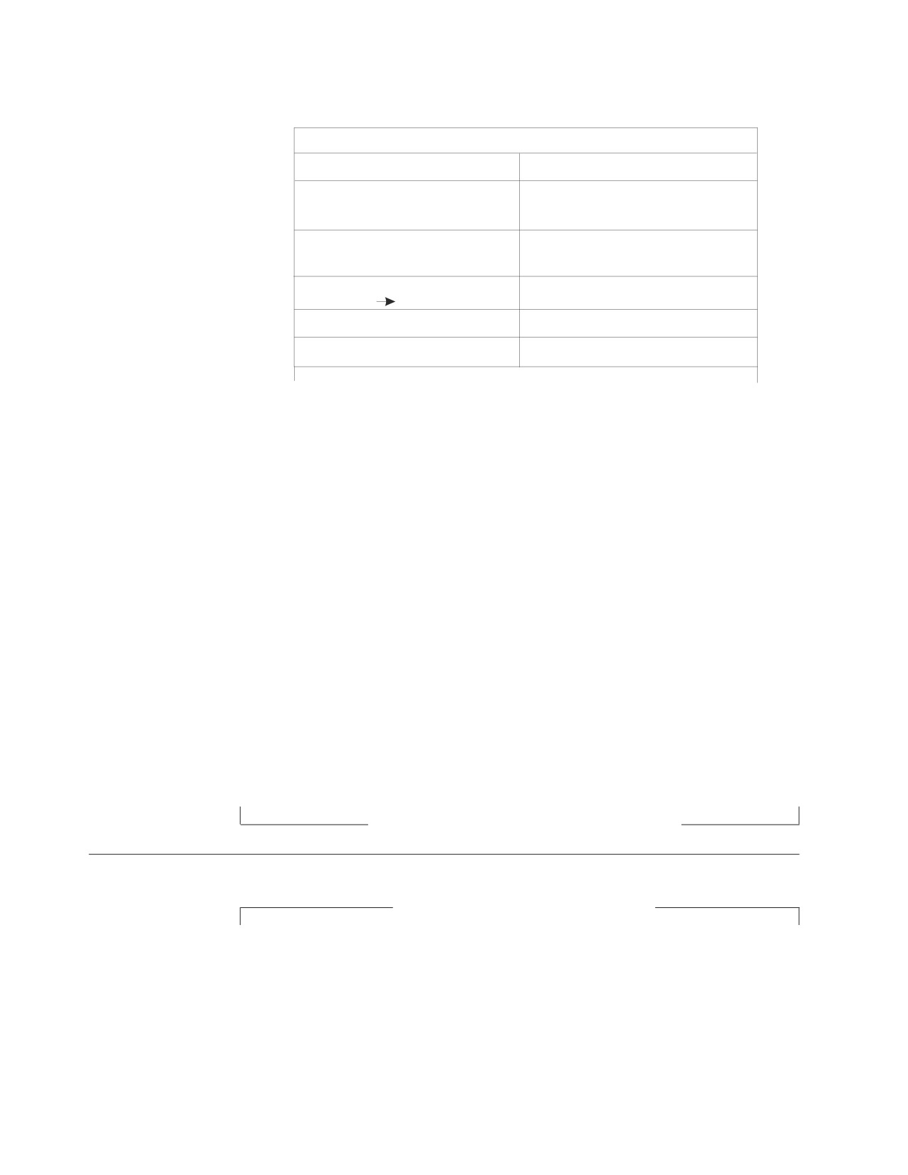
Dec(HEX) RMAR
0(0)
RMAREYEC - 'RMAR' (eyecatcher)
8(8)
RMARLEN - RMAR length (A)
Reserved (Binary zeros) (A) (2)
16(10)
RMARAPPL - Non-architected field
RMARXP - application exit
reserved for the application (A)
24(19)
RMARPC - Post code (A)
(1)
RMARXC - Exit code (R) (2)
32(20)
RMARWLP
RMWL (R)
RMARCNTL - Control Flags (2)
40(28)
RMARUDAT - User data (terminal id)
48(30)
Reserved (16) bytes
Figure 113. Online Resource Adapter Asynchronous Request (RMAR)
(1) 0: Resource adapter should continue
4: Reserved
8: Resource adapter should cancel
Others: Reserved
(2) See "RMAR flags" that follows.
RMAR Flags
OFFSET FIELD NAME BITS
MEANING
36(24)
RMARCNTL
RMARWAIT
1
Tells ARIRSEND to use the
wait exit.
0
Tells ARISEND to not exit
(because call is an EXEC
RDIIN PTC or EXEC SQL
COMMIT/ROLLBACK WORK (R)
RMARDSPR
.1
Tells RMAPI to do a
ROLLBACK via DFHSP. Set by
ARIRSEN when the attempt
to clear did not work
because processing already
finished.
..xx xxxx Reserved. Binary zeros (R)
End of General-Use Programming Interface
Field Procedures
General-Use Programming Interface
A field procedure is a General-Use programming interface. Macro ARIBFPPB is a
General-Use programming interface. General-Use programming interface is defined
in “Programming Interface Information” on page 425.
A field procedure is a user-written exit routine that transforms values in a single
short-string column. When values in the column are changed, or new values are
inserted, the field procedure is run to encode each value, which is then stored.
When values are retrieved from the column, the field procedure is run to decode
each value back to the original string value. A field procedure can be used to alter
290
System Administration
the sorting sequence of values entered in a column. For example, telephone
directories sometimes require that names such as McCabe and MacCabe appear
next to each other. This cannot be achieved with the standard EBCDIC sorting
sequence. Languages that do not use the Roman alphabet have similar
requirements. However, if a column is provided with a suitable field procedure,
you can obtain the desired ordering with the ORDER BY clause.
Any indexes defined on a column that uses a field procedure are built with
encoded values.
The transformation that a field procedure performs on a value is called
field-encoding. The same routine is used to undo the transformation when values
are retrieved; that operation is called field-decoding.
The field procedure is called when a table is created or altered, to define the data
type and attributes of an encoded value to the database manager. That operation is
called field-definition. The data type of the encoded value can be CHAR,
VARCHAR, GRAPHIC, or VARGRAPHIC. If the datatype is VARCHAR the length
must be 254 or less. If the database is VARGRAPHIC, the length must be 127 or
less. For the applicable data types, see the description for the FPVDTYPE field in
Table 30 on page 296. The length, precision, or scale of the encoded value must be
compatible with its data type. Values in columns with a field procedure are
described to the database manager in the following catalog tables:
v SYSTEM.SYSCOLUMNS
v SYSTEM.SYSFIELDS
v SYSTEM.SYSFPARMS
v SYSTEM.SYSKEYCOLS.
For more information about catalog tables, see the DB2 Server for VSE & VM SQL
Reference manual.
Specifying the Field Procedure
To name a field procedure for a column, use the FIELDPROC clause of the
CREATE TABLE or ALTER TABLE statement, followed by the name of the
procedure and, optionally, a list of parameters. You can use a field procedure only
with a short string column. You cannot add a field procedure to an existing
column of a table. You can, however, use the ALTER TABLE statement to add to an
existing table a new column that uses a field procedure. (To do so, you would have
to unload the data, recreate the table, and load the data back into the table.)
The optional parameter list that follows the procedure name is a list of constants,
enclosed in parentheses, called the literal list. The literal list is incorporated into a
data structure called the field procedure parameter value list (FPPVL). That structure is
passed to the field procedure during the field-definition operation. At that time,
the procedure can modify it or return it unchanged. The output form of the FPPVL
is called the modified FPPVL; it is stored in the DB2 Server for VSE catalog as part
of the field description. The modified FPPVL is passed again to the field procedure
when the procedure is called for field-encoding or field-decoding.
When Field Procedures are Called
A field procedure specified for a column is called in three situations:
v For field-definition, when the CREATE TABLE or ALTER TABLE statement that
names the procedure is run. When called, the procedure is expected to:
- Determine whether the data type and attributes of the column are valid
Chapter 13. Creating Installation Exits
291
- Verify the literal list, and change it if required
- Provide the field description of the column
- Define the amount of working storage needed by the field-encoding and
field-decoding processes.
v For field-encoding, when a column value is to be field-encoded. That occurs for
any value that is:
- Inserted in the column by an SQL INSERT or PUT statement, or loaded by
the DBS utility DATALOAD or RELOAD commands
- Changed by an SQL UPDATE statement
- Compared to a column with a field procedure, unless the comparison
operator is LIKE. The value being encoded is a host variable or constant.
v For field-decoding, when a stored value is to be field-decoded back into its
original string value. This occurs for any value that is:
- Retrieved by an SQL SELECT or FETCH statement, or by the DBS utility
DATAUNLOAD or UNLOAD commands
- Compared to another value with the LIKE comparison operator. The value
being decoded is from the column that uses the field procedure.
In this situation the field procedure is called after any DB2 Server for VSE sort.
A field procedure is never called to process a null value.
General Considerations for Writing Field Procedures
Your field procedure must adhere to the following rules:
v It must be written in Assembler.
v Its name must not start with ARI, to avoid conflict with the DB2 Server for VSE
modules.
v It must not call any SVC services.
v It must store registers in an area pointed to by R13, and restore them before
returning.
v It must be serially reusable.
v It must not contain any SQL statements.
v It must reside in the appropriate VSE library and be accessible when the
database manager is running.
v It must support 31-bit addressing (AMODE 31).
Attention: A field procedure should always transform one input data value into
one output data value, unless the parameters are different. This means that the
same field procedure with the same parameters must implement a one to one data
conversion, in both directions. The field-decoding function must be the exact
inverse of the field-encoding function. For example, if a routine encodes
ALABAMA to 01, it must decode 01 to ALABAMA. A violation of this rule can
lead to unpredictable results and possible data corruption.
A Warning about Blanks
When the database manager compares the values of two strings with different
lengths, it temporarily pads the shorter string with blanks (in either single-byte or
double-byte characters, as appropriate) up to the length of the longer string. If the
shorter string is the value of a column with a field procedure, the padding is done
to the encoded value, but the pad character is not encoded. Hence, if the
procedure changes blanks to some other character, encoded blanks at the end of
292
System Administration
the longer string are not equal to padded blanks at the end of the shorter string.
That situation can lead to errors; for example, some strings that should be equal
may not be recognized as such. You should not encode blanks with a field
procedure.
Maintaining Field Procedures
Field procedures are kept in the appropriate VSE library. They can reside in the
PRD2 library as a separate sublibrary. The maximum number of active field
procedures on one installation is 16. If this limit is exceeded, an attempt to load a
field procedure results in an SQLCODE -682 with reason code 4.
Recovering from Abends in Exits
If a field procedure ends abnormally, a message (ARI0022E) to remove the field
procedure from the installation is issued to the operator, the database manager
takes a SNAP dump, and processing continues.
Security with Field Procedures
Since exit routines run as extensions of the database manager and have all its
privileges, they can impact its security and integrity. All field procedures must be
tested and appropriate security measures taken before they are installed on a
system.
Field Procedures for Cultural Sorts
By default, string data is sorted based on the S/390 collating sequence. However,
the collating sequence required for certain alphabets is different from the default
S/390 collating sequence. Users expect that sorted data will match the order that is
culturally correct for them and that searches on data will return the result that is
correct for the sorting sequence of their language. They are at ease with only one
sort order, the one used in their dictionaries, telephone directories, book indices,
and so on.
A way to accommodate special sorting requirements is to use Field Procedures.
Field Procedures can be used to encode data being inserted into a column. The
encoding effectively alters the collating sequence for the data in the column,
enabling the special sorting requirements to be met by the S/390 collating
sequence.
Two field procedures are provided. The procedures are supplied as A-type
members.
The field procedures provided are:
v FP870L2 for Slovenia, Poland and Romania
v FP102CY for Russia, Bulgaria, Serbia and Montenegro
The field procedures are written in Assembler. The field procedure must be
assembled and the corresponding phase must be generated and placed in a library
that is accessible to the database manager when it is running.
Once the phase for the field procedure has been generated and made accessible to
the database manager, it can be used by specifying its name in the FIELDPROC
clause of the CREATE TABLE or ALTER TABLE statement.
Chapter 13. Creating Installation Exits
293
Field Procedure Interface to the Database Manager
This section describes certain control blocks that are used to communicate to a
field procedure, under the following headings:
v
“The Field Procedure Parameter List (FPPL)”
v
“The Work Area”
v
“The Field Procedure Information Block (FPIB)” on page 295
v
“Value Descriptors” on page 295
v
“The Field Procedure Parameter Value List (FPPVL)” on page 296.
The Field Procedure Parameter List (FPPL)
The FPPL is pointed to by register 1 on entry to a field procedure. It, in turn,
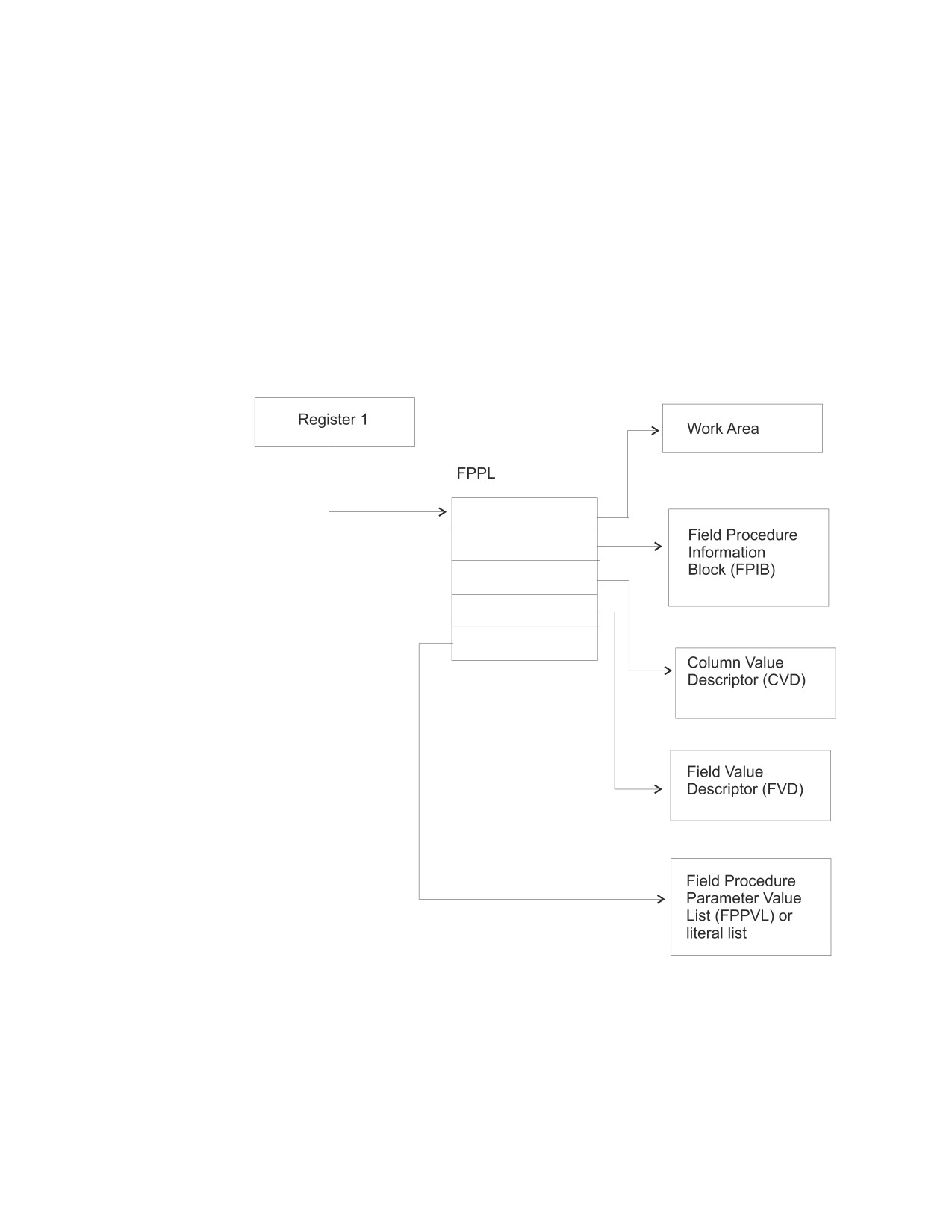
contains the addresses of five other areas, shown in Figure 114. The FPPL and the
areas to which it points are all described by the mapping macro ARIBFPPB, which
is provided as an E-type member.
Figure 114. Field Procedure Parameter List
The Work Area
The work area is an area of storage used by a field procedure as working storage.
A new area is provided each time the procedure is called.
The size of the area you need depends on the way you have programmed your
field-encoding and field-decoding operations. For the field-definition operation, the
database manager passes your routine a value of 512 bytes for the length of the
294
System Administration

work area (FPBWKLN in FPIB). If, for example, the longest work area you need for
field-encoding or field-decoding is 1024 bytes, your field-definition operation must
change the length to 1024. Thereafter, whenever your field procedure is called for
either encoding or decoding, the database manager makes an area of 1024 bytes
available to it.
If 512 bytes is sufficient for your operations, your field-definition operation need
not change the value supplied by the database manager. If you need less than 512
bytes, your field-definition can return a smaller value. However, your
field-definition itself must not use more than 512 bytes.
The Field Procedure Information Block (FPIB)
The FPIB communicates general information to a field procedure. For example, it
tells what operation is to be done, allows the field procedure to signal errors, and
gives the size of the work area. Its format is shown in Table 29.
Table 29. Format of FPIB, Defined in Copy Macro ARIBFPPB
'Hex'
Name
Offset
Data Type
Description
FPBFCODE
0
Signed halfword
Function code.
integer
Code Means
0
Field-encoding
4
Field-decoding
8
Field-definition
FPBWKLN
2
Signed halfword
Length of work area; the maximum is
integer
32767 bytes.
4
Signed halfword
Reserved.
integer
FPBRTNC
6
Character, 2 bytes
Return code set by field procedure.
FPBRSNC
8
Character, 4 bytes
Reason code set by field procedure.
FPBTOKP
12
Address
Address of a 40-byte area, within the
work area or within the field
procedure’s static area, containing an
error message.
Value Descriptors
Value descriptors describe the data type and other attributes of a value. They are
used with field procedures in these ways:
v During field definition, they describe each constant in the field procedure
parameter value list (FPPVL). The set of these value descriptors is part of the
FPPVL control block.
v During field encoding and field decoding, the decoded (column) value and the
encoded (field) value are described by the column value descriptor (CVD) and
the field value descriptor (FVD).
The CVD contains a description of a column value and, if appropriate, the value
itself. During field encoding, the CVD describes the value to be encoded; during
field decoding, it describes the decoded value to be supplied by the field
procedure; and during field definition, it describes the column as defined in the
CREATE TABLE or ALTER TABLE statement.
The FVD contains a description of a field value and, if appropriate, the value itself.
During field-encoding, the FVD describes the encoded value to be supplied by the
Chapter 13. Creating Installation Exits
295

field procedure; during field-decoding, it describes the value to be decoded.
Field-definition must put into the FVD a description of the encoded value.
The format of value descriptors is shown in Table 30.
Table 30. Format of Value Descriptors
'Hex'
Name
Offset
Data Type
Description
FPVDTYPE
0
Signed halfword
Data type of the value:
integer
Code Means
16
CHAR
20
VARCHAR
24
GRAPHIC
28
VARGRAPHIC
FPVDVLEN
2
Signed halfword
For a varying-length string value, its
integer
maximum length.
FPVDVALE
4
None
The value. If the value is a
varying-length string, the first half
word is the value’s actual length in
bytes. This field is not present in a
CVD, or in an FVD used as input to
the field-definition operation.
The Field Procedure Parameter Value List (FPPVL)
The FPPVL communicates the literal list, supplied in the CREATE TABLE or
ALTER TABLE statement, to the field procedure during field definition. At that
time the field procedure can reformat the FPPVL. The reformatted FPPVL is stored
in SYSTEM.SYSFPARMS and communicated to the field procedure during field
encoding and field decoding as the modified FPPVL.
Its format is shown in Table 31.
Table 31. Format of FPPVL, Defined in Copy Macro ARIBFPPB
'Hex'
Name
Offset
Data Type
Description
FPPVLEN
0
Signed halfword
Length in bytes of the area containing
integer
FPPVCNT and FPPVVDS. At least 254
for field-definition.
FPPVCNT
2
Signed halfword
Number of value descriptors that
integer
follow, equal to the number of
parameters in the FIELDPROC clause.
Zero if no parameters were listed.
FPPVVDS
4
Structure
For each parameter in the FIELDPROC
clause, there is:
v A signed fullword integer giving the
length of the following value
descriptor.
v A value descriptor.
Field-Definition (Function Code 8)
The input provided to the field-definition operation, and the output required, are
as follows:
296
System Administration
On ENTRY
The registers have the following information:
Register
Contains
1
Address of the field procedure parameter list
(FPPL). For a schematic diagram, see Figure 114 on
page 294.
2-12
Unknown values that must be restored on exit.
13
Address of the register save area.
14
Return address.
15
Address of entry point of exit routine.
The contents of all other registers, and of fields not listed below, are unpredictable.
The work area consists of 512 contiguous uninitialized bytes.
The FPIB has the following information:
Field
Contains
FPBFCODE
8, the function code.
FPBWKLN
512, the length of the work area.
The CVD has the following information:
Field
Contains
FPVDTYPE
One of these codes for the data type of the column
value:
Code Means
16
CHAR
20
VARCHAR
24
GRAPHIC
28
VARGRAPHIC
FPVDVLEN
The length attribute of the column.
The FPVDVALE field is omitted.
The FVD provided is 4 bytes long.
The FPPVL has the following information:
Field
Contains
FPPVLEN
The length, in bytes, of the area containing the
parameter value list. The minimum value is 254,
even if there are no parameters.
FPPVCNT
The number of value descriptors that follow; zero
if there are no parameters.
FPPVVDS
A contiguous set of value descriptors, one for each
parameter in the parameter value list, each
preceded by a 4-byte length field.
Chapter 13. Creating Installation Exits
297
On EXIT
The registers must have the following information:
Register
Contains
2-12
The values they contained on entry.
15
The integer zero if the column described in the
CVD is valid for the field procedure; otherwise the
value must not be zero.
Fields listed below must be set as shown; all other fields must remain as on entry.
The FPIB must have the following information:
Field
Contains
FPBWKLN
The length, in bytes, of the work area to be
provided to the field-encoding and field-decoding
operations; 0 if no work area is required.
FPBRTNC
An optional 2-byte character return code, defined
by the field procedure; blanks if no return code is
given.
FPBRSNC
An optional 4-byte character reason code, defined
by the field procedure; blanks if no reason code is
given.
FPBTOKP
Optionally, the address of a 40-byte error message
residing in the work area or in the field
procedure’s static area; zeros if no message is
given.
Errors signaled by a field procedure result in an SQL return code of -681, which is
set in the SQL communication area (SQLCA). The contents of FPBRTNC and
FPBRSNC, and the error message pointed to by FPBTOKP, are also placed into the
tokens, in SQLCA, as field SQLERRMT. The meaning of the error message is
determined by the field procedure.
The FVD must have the following information:
Field
Contains
FPVDTYPE
The numeric code for the data type of the field
value. Any of the data types listed in Table 30 on
page 296 is valid.
FPVDVLEN
The length of the field value.
Field FPVDVALE must not be set; the length of the FVD is 4 bytes only.
The FPPVL can be redefined to suit the field procedure, and returned as the
modified FPPVL, subject to the following restrictions:
v The field procedure must not increase the length of the FPPVL.
v The FPPVLEN must contain the actual length of the modified FPPVL, or 0 if no
parameter list is returned.
The modified FPPVL is recorded in the SYSTEM.SYSFPARMS catalog table and is
passed again to the field procedure during field-encoding and field-decoding. The
298
System Administration
modified FPPVL need not have the format of a field procedure parameter list, and
it need not describe constants by value descriptors.
Field-Encoding (Function Code 0)
The input provided to the field-encoding operation, and the output required, are as
follows:
On ENTRY
The registers have the following information:
Register
Contains
1
Address of the field procedure parameter list
(FPPL). For a schematic diagram, see Figure 114 on
page 294.
2-12
Unknown values that must be restored on exit.
13
Address of the register save area.
14
Return address.
15
Address of entry point of exit routine.
The contents of all other registers, and of fields not listed below, are unpredictable.
The work area is contiguous, uninitialized, and of the length specified by the field
procedure during field-definition.
The FPIB has the following information:
Field
Contains
FPBFCODE
0, the function code.
FPBWKLN
The length of the work area.
The CVD has the following information:
Field
Contains
FPVDTYPE
The numeric code for the data type of the column
value, as shown in Table 30 on page 296.
FPVDVLEN
The length of the column value.
FPVDVALE
The column value; if the value is a variable-length
string, the first halfword contains its length.
The FVD has the following information:
Field
Contains
FPVDTYPE
The numeric code for the data type of the field
value.
FPVDVLEN
The length of the field value.
FPVDVALE
An area of unpredictable content that is as long as
the field value.
The modified FPPVL produced by the field procedure during field-definition is
provided if it exists.
Chapter 13. Creating Installation Exits
299
On EXIT
The registers must have the following information:
Register
Contains
2-12
The values they contained on entry.
15
The integer zero if the encoding is successful;
otherwise the value must not be zero.
The FVD must contain the encoded (field) value in field FPVDVALE. If the value is
a varying-length string, the first halfword must contain its length.
The FPIB may have the following information:
Field
Contains
FPBRTNC
An optional 2-byte character return code, defined
by the field procedure; blanks if no return code is
given.
FPBRSNC
An optional 4-byte character reason code, defined
by the field procedure; blanks if no reason code is
given.
FPBTOKP
Optionally, the address of a 40-byte error message
residing in the work area or in the field
procedure’s static area; zeros if no message is
given.
Errors signaled by a field procedure result in an SQL return code of -681, which is
set in the SQL communication area (SQLCA). The contents of FPBRTNC and
FPBRSNC, and the error message pointed to by FPBTOKPT, are also placed into
the tokens, in SQLCA, as field SQLERRMT. The meaning of the error message is
determined by the field procedure.
All other fields must remain as on entry.
Field-Decoding (Function Code 4)
The input provided to the field-decoding operation, and the output required, are as
follows:
On ENTRY
The registers have the following information:
Register
Contains
1
Address of the field procedure parameter list
(FPPL). For a schematic diagram, see Figure 114 on
page 294.
2-12
Unknown values that must be restored on exit.
13
Address of the register save area.
14
Return address.
15
Address of entry point of exit routine.
The contents of all other registers, and of fields not listed below, are unpredictable.
300
System Administration
The work area is contiguous, uninitialized, and of the length specified by the field
procedure during field-definition.
The FPIB has the following information:
Field
Contains
FPBFCODE
4, the function code.
FPBWKLN
The length of the work area.
The CVD has the following information:
Field
Contains
FPVDTYPE
The numeric code for the data type of the column
value, as shown in Table 30 on page 296.
FPVDVLEN
The length of the column value.
FPVDVALE
An area of unpredictable content that is as long as
the column value.
The FVD has the following information:
Field
Contains
FPVDTYPE
The numeric code for the data type of the field
value.
FPVDVLEN
The length of the field value.
FPVDVALE
The field value; if the value is a varying-length
string, the first halfword contains its length.
The modified FPPVL, produced by the field procedure during field-definition, is
provided if it exists.
On EXIT
The registers must have the following information:
Register
Contains
2-12
The values they contained on entry.
15
The integer zero if the decoding is successful;
otherwise the value must not be zero.
The CVD must contain the decoded (column) value in field FPVDVALE. If the
value is a varying-length string, the first halfword must contain its length.
The FPIB may have the following information:
Field
Contains
FPBRTNC
An optional 2-byte character return code, defined
by the field procedure; blanks if no return code is
given.
FPBRSNC
An optional 4-byte character reason code, defined
by the field procedure; blanks if no reason code is
given.
FPBTOKP
Optionally, the address of a 40-byte error message
Chapter 13. Creating Installation Exits
301
residing in the work area or in the field
procedure’s static area; zeros if no message is
given.
Errors signaled by a field procedure result in an SQL return code of -681, which is
set in the SQL communication area (SQLCA). The contents of FPBRTNC and
FPBRSNC, and the error message pointed to by FPBTOKP, are also placed into the
tokens, in SQLCA, as field SQLERRMT. The meaning of the error message is
determined by the field procedure.
All other fields must remain as on entry.
A Sample Exit
Figure 115 on page 303 shows an example of a field procedure.
302
System Administration
FLCTFLC TITLE ’DB2 Server for VSE FIELD PROCEDURE EXAMPLE’
FLCTFLC START 0
FLCTFLC AMODE 31
FLCTFLC RMODE ANY
************************************************************
DB2 Server for VSE FIELD PROCEDURE TO CONVERT
FIXED LENGTH CHARACTER TO FIXED
LENGTH CHARACTER USING A LOOKUP TABLE
************************************************************
SPACE 3
PRINT GEN
USING FLCTFLC,R3
BASE REGISTER
USING FPIB,R9
COMMON INFORMATION BLOCK
USING FPVD,R10
VALUE DESCRIPTOR
USING FPPL,R11
PARAMETER LIST
USING WA,R12
WORK AREA
USING FPPVL,R8
PARAMETER VALUE LIST
USING TBLHDRD,R7
TABLE HEADER
SPACE 3
*************************************************************
SET UP MAIN LINE
RETURN R14
*************************************************************
SPACE 3
SAVE
(14,12),,FLCTFLC
LR
R3,R15
LOAD BASE REGISTER
LR
R11,R1
PARAMETER LIST POINTER
L
R12,FPPWORK
WORK AREA ADDRESS
ST
R13,SAVE13
L
R9,FPPFPIB
COMMON INFORMATION BLOCK
MVC
FPBRTNC,=AL2(FPBRC0)
RETURN CODE = 0
LH
R2,FPBFCODE
L
R15,FDLFC(R2)
SELECT APPROPRIATE ROUTINE
LA
R14,RET1
BR
R15
RET1
DS
0H
PACK
WADW,FPBRTNC
SET RETURN CODE R15
CLI
FPBRTNC+L’FPBRTNC-1,C’ ’
BNE
NOTBL
PACK
WADW,FPBRTNC(L’FPBRTNC-1)
NOTBL
DS
0H
CVB
R15,WADW
L
R13,SAVE13
RETURN (14,12),T,RC=(15)
LTORG
FDLFC
DC
A(ENCODE,DECODE,DEFINE)
SPACE 3
Figure 115. Field Procedure Example (Part 1 of 9)
Chapter 13. Creating Installation Exits
303
****************************************************************
ENCODING ROUTINE
RETURN R14
****************************************************************
SPACE 3
ENCODE DS
0H
MVC FUNCT,=C’ENCD’
LA
R5,B1
B
CHKINP
CHECK INPUT DESCRIPTION
B1
DS
0H
LA
R5,B2
B
CHKOUT
CHECK OUTPUT DESCRIPTION
B2
DS
0H
SPACE 3
******************************************************************
LOOKUP ROUTINE FOR ENCODING
******************************************************************
SPACE 3
L
R10,FPPCVD
INPUT VALUE
L
R6,TABADDR
TOP OF LOOKUP TABLE
LA
R5,B3
B
SETLUP
SET UP LOOKUP VARIABLES
B3
DS
0H
SPACE 3
*****************************************************************
SET UP LOOP VARIABLES
*****************************************************************
SPACE 3
SR
R4,R4
CLEAR R4
IC
R4,ILEN
LENGTH FOR COMPARE
SH
R4,=H’1’
-1
ITOP
DS
0H
EX
R4,CLCINST
BE
IHIT
A
R6,INCRLEN
INCREMENT TO NEXT ENTRY
BCT
R13,ITOP
LA
R13,ER5
B
ERROR4
IHIT
DS
0H
L
R10,FPPFVD
SPACE 3
Figure 115. Field Procedure Example (Part 2 of 9)
304
System Administration
***************************************************************
SET UP MOVE INSTRUCTION
***************************************************************
SPACE 3
SR
R13,R13
CLEAR R13
IC
R13,OLEN
OUTPUT LENGTH
SH
R13,=H’1’
-1
SR
R5,R5
CLEAR R5
IC
R5,ILEN
INPUT LENGTH
AR
R6,R5
POINT TO OUTPUT VALUE IN TABLE
EX
R13,MVCINST
BR
R14
SPACE 3
*******************************************************************
MOVE AND COMPARE INSTRUCTION FOR EXECUTION INSTRUCTION
*******************************************************************
SPACE 3
DS
0H
CLCINST CLC
0(1,R6),FPVDVALE
MVCINST MVC
FPVDVALE,0(R6)
SPACE 3
*******************************************************************
DECODING ROUTINE
*******************************************************************
SPACE 3
DECODE DS
0H
MVC FUNCT,=C’DECD’
LA
R5,BB1
B
CHKINP
CHECK INPUT DESCRIPTION
BB1
DS
0H
LA
R5,BB2
B
CHKOUT
CHECK OUTPUT DESCRIPTION
BB2
DS
0H
SPACE 3
*******************************************************************
LOOKUP ROUTINE FOR DECODING
*******************************************************************
SPACE 3
L
R10,FPPFVD
OUTPUT VALUE
L
R6,TABADDR
TOP OF LOOKUP TABLE
LA
R5,BB3
B
SETLUP
SET LOOKUP VARIABLES
BB3
DS
0H
SPACE 3
Figure 115. Field Procedure Example (Part 3 of 9)
Chapter 13. Creating Installation Exits
305
*******************************************************************
SET UP LOOP VARIABLES
*******************************************************************
SPACE 3
SR
R4,R4
CLEAR R4
IC
R4,OLEN
LENGTH FOR COMPARE
SH
R4,=H’1’
-1
SR
R5,R5
CLEAR R5
IC
R5,ILEN
INPUT LENGTH
AR
R6,R5
POINT TO OUTPUT VALUE IN TABLE
OTOP
DS
0H
EX
R4,CLCINST
BE
OHIT
A
R6,INCRLEN
POINT TO NEXT ENTRY
BCT
R13,OTOP
LA
R13,ER8
B
ERROR4
OHIT
DS
0H
L
R10,FPPCVD
SPACE 3
******************************************************************
SET UP MOVE INSTRUCTION
******************************************************************
SPACE 3
SR
R13,R13
CLEAR R13
IC
R13,ILEN
INPUT LENGTH
SR
R6,R13
POINT TO INPUT VALUE IN TABLE
SH
R13,=H’1’
-1
EX
R13,MVCINST
BR
R14
SPACE 3
*******************************************************************
DEFINE ROUTINE
RETURN R14
*******************************************************************
SPACE 3
DEFINE DS
0H
MVC FUNCT,=C’DEFN’
LA
R5,BBB1
B
CHKINP
BBB1
DS
0H
SPACE 3
******************************************************************
UPDATE WORK AREA LENGTH IN FPIB
******************************************************************
MVC FPBWKLN,=Y(WAEND-WA)
SPACE 3
Figure 115. Field Procedure Example (Part 4 of 9)
306
System Administration
********************************************************************
SET UP FIELD VALUE DESCRIPTOR
********************************************************************
SPACE 3
L
R10,FPPFVD
OUTPUT DESCRIPTOR
MVC
FPVDTYPE,=Y(FPVDTCHR)
FIXED CHARACTER
MVI
FPVDVLEN,X’00’
AH
R10,=H’3’
MVC
0(1,R10),OLEN
BR
R14
SPACE 3
********************************************************************
CHECK INPUT ROUTINE
RETURN R5
********************************************************************
SPACE 3
CHKINP
DS
0H
L
R8,FPPPVL
L
R10,FPPCVD
INPUT DESCRIPTOR
CLC
=Y(FPVDTCHR),FPVDTYPE
FIXED CHARACTER ?
BNE
CHKINPE1
CLC
FPPVCNT,=H’1’
ONLY ONE PARAMETER ?
BNE
CHKINPE2
NO, ERROR
LA
R7,TBLHDR
POINT TO TABLE HEADER TABLE
LOOP1
DS
0H
CLC
CODE,FPPVVDS+8
IS VALUE IN TABLE
BNE
CPEND
NO, INCREMENT
B
CINCL
YES, A HIT
CPEND
DS
0H
AH
R7,=H’8’
EACH TABLE ENTRY 8 BYTES
CLI
CODE,X’FF’
END OF TABLE?
BNE
LOOP1
NO
LA
R13,ER3
B
ERROR8
YES, ERROR
CINCL
DS
0H
CLC
ILEN,FPVDVLEN+1
CHECK INPUT LENGTH
BER
R5
LA
R13,ER4
B
ERROR4
CHKINPE1
DS
0H
LA
R13,ER1
B
ERROR4
CHKINPE2
DS
0H
LA
R13,ER2
Figure 115. Field Procedure Example (Part
5 of 9)
Chapter 13. Creating Installation Exits
307
ERROR8
DS
0H
MVC
FPBRTNC,=AL2(FPBRC8)
B
ERROR
ERROR4
DS
0H
MVC
FPBRTNC,=AL2(FPBRC4)
ERROR
DS
0H
MVC
FPBRSNC,FUNCT
ST
R13,FPBTOKP
BR
R14
SPACE 3
*************************************************************
CHECK OUTPUT DESCRIPTOR
RETURN R5
*************************************************************
SPACE 3
CHKOUT DS
0H
L
R10,FPPFVD
FIELD DESCRIPTOR
CLC
=Y(FPVDTCHR),FPVDTYPE
FIXED CHARACTER ?
BNE
CHKOUTE1
CLC
OLEN,FPVDVLEN+1
CHECK OUTPUT LENGTH
BER
R5
LA
R13,ER6
B
ERROR4
CHKOUTE1 DS
0H
LA
R13,ER7
B
ERROR4
SPACE 3
*******************************************************************
SET UP LOOKUP VARIABLE ROUTINE
RETURN R5
*******************************************************************
SPACE 3
SETLUP DS
0H
SR
R4,R4
CLEAR R4
IC
R4,ILEN
INPUT LENGTH
ST
R4,INCRLEN
SAVE INPUT LENGTH
SR
R4,R4
CLEAR R4
IC
R4,OLEN
OUTPUT LENGTH
A
R4,INCRLEN
ADD INPUT LENGTH
ST
R4,INCRLEN
STORE TABLE ENTRY LENGTH
SR
R13,R13
CLEAR R13
IC
R13,NENTR
NUMBER OF ENTRIES
BR
R5
SPACE 3
Figure 115. Field Procedure Example (Part 6 of 9)
308
System Administration
********************************************************************
ERROR MESSAGES
********************************************************************
ER1
DC
CL40’INVALID COLUMN TYPE’
ER2
DC
CL40’INVALID NUMBER OF PARAMETERS’
ER3
DC
CL40’INVALID PARAMETER VALUE’
ER4
DC
CL40’INVALID COLUMN LENGTH’
ER5
DC
CL40’INVALID INPUT VALUE TO ENCODE’
ER6
DC
CL40’INVALID FIELD LENGTH’
ER7
DC
CL40’INVALID FIELD TYPE’
ER8
DC
CL40’INVALID FIELD VALUE TO DECODE’
SPACE 3
**********************************************************************
TABLE HEADER TABLE
**********************************************************************
TBLHDR DS
0F
**********************************************************************
FIRST TABLE CODE = ’A’
**********************************************************************
DC
C’A’
CODE
DC
X’01’
INPUT LENGTH
DC
X’01’
OUTPUT LENGTH
DC
X’03’
NUMBER OF ENTRIES
DC
A(TABA)
ADDRESS OF LOOKUP TABLE
**********************************************************************
SECOND TABLE CODE = ’B’
**********************************************************************
DC
C’B’
CODE
DC
X’04’
INPUT LENGTH
DC
X’01’
OUTPUT LENGTH
DC
X’22’
NUMBER OF ENTRIES
DC
A(TABB)
ADDRESS OF LOOKUP TABLE
*******************************************************************
PUT ADDITIONAL TABLE HEADER ENTRIES HERE
*******************************************************************
SPACE 3
*******************************************************************
END OF TABLE HEADERS
*******************************************************************
DC
X’FF’
SPACE 3
TABA
DS
0H
DC
C’H’
HIGH
DC
C’7’
DC
C’M’
MEDIUM
DC
C’5’
DC
C’L’
LOW
DC
C’3’
SPACE 3
Figure 115. Field Procedure Example (Part 7 of 9)
Chapter 13. Creating Installation Exits
309
TABB
DS
0H
DC
C’AAA ’
DC
X’F0’
240
DC
C’AA+ ’
DC
X’E6’
230
DC
C’AA
’
DC
X’DC’
220
DC
C’AA- ’
DC
X’D2’
210
DC
C’A+
’
DC
X’C8’
200
DC
C’A1
’
DC
X’BE’
190
DC
C’A
’
DC
X’B4’
180
DC
C’A-
’
DC
X’AA’
170
DC
C’BBB+’
DC
X’A0’
160
DC
C’BBB ’
DC
X’96’
150
DC
C’BBB-’
DC
X’8C’
140
DC
C’BB+ ’
DC
X’82’
130
DC
C’BB
’
DC
X’78’
120
DC
C’BB- ’
DC
X’6E’
110
DC
C’B+
’
DC
X’64’
100
DC
C’B
’
DC
X’5A’
90
DC
C’B-
’
DC
X’50’
80
DC
C’CCC ’
DC
X’46’
70
DC
C’CC
’
DC
X’3C’
60
DC
C’C
’
DC
X’32’
50
DC
C’D
’
DC
X’28’
40
DC
C’NR
’
DC
X’1E’
SPACE
3
Figure 115. Field Procedure Example (Part
8 of 9)
310
System Administration
**********************************************************************
TABLE HEADER TABLE DSECT
**********************************************************************
TBLHDRD DSECT
CODE
DS
CL1
ILEN
DS
CL1
OLEN
DS
CL1
NENTR
DS
CL1
TABADDR
DS
A
SPACE 3
*********************************************************************
WORK AREA
*********************************************************************
SPACE 3
WA
DSECT
SAVE13
DS
F
INCRLEN
DS
F
FUNCT
DS
CL4
WADW
DS
D
WAEND
DS
0H
SPACE 3
ARIBFPPB
R0
EQU
0
R1
EQU
1
R2
EQU
2
R3
EQU
3
R4
EQU
4
R5
EQU
5
R6
EQU
6
R7
EQU
7
R8
EQU
8
R9
EQU
9
R10
EQU
10
R11
EQU
11
R12
EQU
12
R13
EQU
13
R14
EQU
14
R15
EQU
15
END
Figure 115. Field Procedure Example (Part 9 of 9)
End of General-Use Programming Interface
Chapter 13. Creating Installation Exits
311
312
System Administration
Chapter 14. Using a DRDA Environment
The Distributed Relational Database Architecture (DRDA) environment provides
the architecture for access to data that is distributed across different operating
systems. The application requester and the application server do not have to be
running with the same database manager.
This chapter discusses:
v Benefits and added responsibilities of a DRDA environment
v Types of distributed access
v Preparing to implement DRDA
v Installing and removing the DRDA code
v Using DRDA
v Creating the DBS Utility on remote DRDA application servers
v Using ISQL on remote DRDA application servers
v Two phase commit processing
Not all extended features are supported by the DRDA protocol. Refer to
Appendix H, “DRDA Considerations,” on page 385 for more details.
For detailed information on Distributed Relational Database Architecture, see the
manuals in the Distributed Relational Database Architecture Library listed in the
Bibliography.
Benefits of Using the DRDA Protocol
The DRDA option does the following:
v Makes DB2 Server for VSE data accessible to users equipped with the DRDA
application requester function. Users on platforms such as OS/2, AIX, OS/400,
OS/390, or Microsoft Windows™ can run applications that utilize DRDA remote
unit of work or DRDA distributed unit of work processing to access data
residing in DB2 Server for VSE application servers.
v Enables DB2 Server for VSE users to use remote unit of work access to work
with data on non-DB2 Server for VSE application servers. This allows access to
data that would otherwise remain unavailable.
To support this access, application programs can contain SQL statements that are
specific to the target system, and both the DBS Utility and ISQL can be run on
non-DB2 Server for VSE application servers. The SQL statements in these
application programs can be static, dynamic, and extended dynamic, even if the
target system does not support extended dynamic statements. In addition, portable
packages can be loaded on non-DB2 Server for VSE application servers.
The DRDA option provides the following additional functions:
v To determine the status of connections in an environment that may have local
and remote systems, you can use the SHOW CONNECT operator command.
v To aid in the diagnosis of errors, first failure data capture is automatically
performed. IBM service can use the captured data for diagnosis, decreasing the
probability of having to rerun applications to acquire data for diagnosis.
v Another aid in the diagnosis of errors is the LUWID support. The LUWID is a
unique identifier associated with each application requester connection. It is
313
composed of four parts: network id, LU name, LUW instance number, and LUW
sequence number. This provides additional information that may be required in
problem diagnosis.
Added Responsibilities in Using the DRDA Protocol
Use of the DRDA protocol requires assuming extra responsibilities that are usually
not required in a non-distributed environment.
Because the communications between database managers can be in different time
zones or countries, some allowance must be made for scheduling and
communication problems (particularly when different languages are involved).
The operation of applications may be similar, but the different platforms will
require modifications. These modifications may require that as system
administrator you become familiar with the terminology used on non-DB2 Server
for VSE database managers. In situations such as adding users, assigning resources,
ascertaining the authorization schemes available, and performing diagnosis, the
different terminology of the different database managers can lead to
misunderstandings. Similarly, because communications software is involved, you
may have to become familiar with communication terminology that may not be
required in a non-distributed environment.
Applications that run in a DRDA environment also require attention. In some
instances, they may have to be recoded to compensate for system-to-system
processing differences. As an example, consider the differences between collating
sequences on different database managers. Quite apart from the differences
between the ASCII and EBCDIC collating sequences, differences can occur between
EBCDIC collating sequences on two different database managers: the same
character can appear in a different sequence because of the way in which a system
processes information. If an application is not recoded to correct for this variability,
the results generated by that application can be misleading.
Types of Distributed Access
Two types of access to data in distributed relational database systems are currently
available. They are remote unit of work, which is also known as DRDA1, and
distributed unit of work, which is also known as DRDA2.
Remote Unit of Work
Remote unit of work (RUOW) allows a user or an application to read or update
data at one remote location per unit of work. With remote unit of work, you can
have many SQL statements within a unit of work. You can access one database
management system with each SQL statement, and you can access one database
management system within a unit of work.
Consider a banking example. Using remote unit of work, you can transfer funds
from a savings account table to a checking account table, if both tables are at the
same remote location. Figure 116 on page 315 shows how the application first
requests an update to the savings account table (1) and then requests an update to
the checking account table (2).
314
System Administration
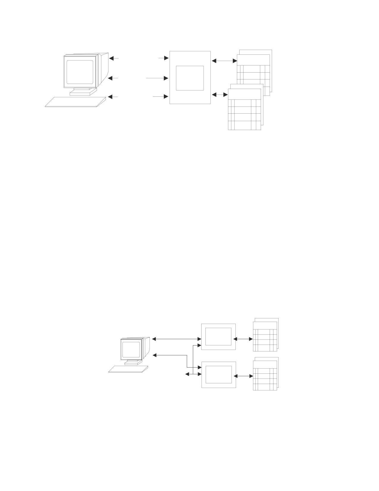
Savings/Checking System
1. Subtract from
Savings
Savings
Funds
Transfer
2. Add to
RDBMS
Checking
Checking
3. Commit or
Roll back
Figure 116. Remote unit of work
If both requests are processed successfully, the application can direct the database
management system to commit both updates (3). If either request is not processed
successfully, the application can issue a ROLLBACK, leaving both tables as they
were before the transaction began. This ensures that requests are neither lost nor
duplicated.
Distributed Unit of Work
Distributed unit of work lets a user or application program read or update data at
multiple locations within a single unit of work. With distributed unit of work, you
can:
v Have many SQL statements within a unit of work
v Access one database management system with each SQL statement
v Access many database management systems within a unit of work.
Using the banking example (see Figure 117), imagine that the savings account table
and the checking account table are on two different computer systems. Distributed
unit of work processing permits an application to debit the savings account (1),
credit the checking account (2), and either commit or roll back the operations in
both computer systems (3), treating all of the changes as a single transaction, or
unit of work.
Savings
1. Subtract from
RDBMS
Savings
Funds
Transfer
2. Add to
Checking
Checking
3. Commit or
Roll back
RDBMS
Figure 117. Distributed unit of work
Commit and rollback are coordinated at all locations so that if a failure occurs
anywhere in the system, data integrity is preserved. If there was a failure in the
middle of the banking transaction just described, and commit or rollback was not
coordinated, the savings account could be debited money and the checking account
might not be credited the money. This costly error is avoided by the coordination
Chapter 14. Using a DRDA Environment
315
of commit and rollback, or two-phase commit processing. For more information on
two-phase commit processing, see “Two-Phase Commit Processing” on page 325.
Summary of DRDA Support in DB2 Server for VSE
Table 32 summarizes the level of DRDA support available for the DB2 Server for
VSE application server (AS) and application requester (AR):
Table 32. DRDA Support in DB2 Server for VSE
VM or VSE AS
VM AR
VSE Batch AR
VSE Online AR
RUOW over SNA
yes
yes
no
yes
RUOW over TCP/IP yes
yes
yes
yes
DUOW over SNA
yes
no
no
no
DUOW over TCP/IP no
no
no
no
Preparing to Implement DRDA
You can use the application requester, the application server, or both in a
distributed environment. This section provides a checklist of the required tasks for
implementing DRDA over SNA. For information on implementing DRDA over
TCP/IP, refer to Chapter 15, “Using TCP/IP with DB2 Server for VSE,” on page
335. For detailed information on DRDA, see the Distributed Relational Database
Connectivity Guide.
On the Application Requester
The following tasks must be completed before a batch or online application
requester can access a remote server via TCP/IP:
v The DRDA code must be activated. See “Installing the DRDA Code on the
Application Requester” on page 320 for more details.
v VSE TCP/IP support must be installed and enabled.
v The DBNAME Directory must be updated to identify the remote application
server as accessible via TCP/IP.
v Optionally, the SQLGLOB file can be updated with default parameters for
application requesters accessing remote servers.
The following tasks must be completed before a CICS online application requester
can access a remote DRDA application server via SNA:
v Update the DBNAME Directory with the remote application server’s SNA
information
v Issue CEDA DEFINE CONNECTION (or equivalent DFHCSDUP) to define the
remote LU associated with the remote application server. See Figure 12 on page
31 for an example of the CEDA DEFINE CONNECTION.
v Issue CEDA DEFINE SESSION to define the LU 6.2 sessions with the remote
system.
v Define the CCSIDs-related phases to CICS. Figure 118 on page 317 shows the
DFHCSDUP commands for the new CCSIDs-related programs that must be
added.
316
System Administration
* Phase for SYSCCSIDS
DEFINE PROGRAM(ARISCCSD) GROUP(DB2710) LANGUAGE(ASSEMBLER)
* Phase for SYSSTRINGS
DEFINE PROGRAM(ARISSTRD) GROUP(DB2710) LANGUAGE(ASSEMBLER)
* Phase for SYSCHARSETS
DEFINE PROGRAM(ARISSCRD) GROUP(DB2710) LANGUAGE(ASSEMBLER)
Figure 118. Sample commands of the DFHCSDUP command to define a program
v Define the Online Resource Adapter DRDA Router program ARI0RTRM to CICS.
Figure 119 shows the DFHCSDUP commands for the new program that must be
added.
* Phase for Online Resource Adapter DRDA Router
DEFINE PROGRAM(ARI0RTRM) GROUP(DB2710) LANGUAGE(ASSEMBLER)
Figure 119. Sample commands of the DFHCSDUP command to define a program
v Activate the DRDA code for the Online Resource Adapter. See “Installing the
DRDA Code on the Application Requester” on page 320 for more information.
v Issue CIRB or CIRA to enable online access to the remote application server.
v Issue DSQU (if a CICS user) to override any default global SQLGLOB parameter
settings, if required. The SQLGLOB environmental parameters are used by the
Online Resource Adapter when accessing a remote application server. Note:
When the Online Resource Adapter processes an SQL request from ISQL, CBND,
or any task started by the EXEC CICS START command, the Online Resource
Adapter uses the default global SQLGLOB parameter values, instead of the user
SQLGLOB parameter values.
On the Application Server
Several CICS definitions are required in order to use DRDA support on the VSE
application server. See the following sections for more details.
CICS Transaction Definitions Required for DRDA
All DB2 Server for VSE transactions that are used for DRDA processing must be
defined to CICS using the Resource Definition Online (RDO) facility or
DFHCSDUP commands. Each Transaction Program Name (TPN) in the DBNAME
directory that is an APPC-to-XPPC exchange (AXE) transaction must be defined to
CICS. The default DBNAME directory entry defines a TPN with a hexadecimal
value of X’07F6C4C2’. To define this default TPN to CICS, refer to the CAXE entry
in Table 33 on page 318. Additional AXE transactions can be added with different
TRANS IDs and, optionally, the TCLASS parameter to provide access control. The
TCLASS parameter is not required for the default CAXE entry. To define an
alphanumeric TPN, refer to the CAX2 entry in Table 33 on page 318.
The DB2 Server for VSE DRDA2 administration routines must also be defined to
CICS if you intend to establish protected conversations between a remote client
and the DB2 Server for VSE application server. This includes the DB2 Server for
VSE DAXP and DAXT transactions. The DAXP transaction sets parameters that are
used when an AXE transaction subsequently autostarts DRDA2 support. The
DAXT transaction is responsible for disabling DRDA2 support.
Use the sample entries in Table 33 on page 318 as a guideline for making your
transaction definitions.
Chapter 14. Using a DRDA Environment
317

Table 33. Defining the DB2 Server for VSE DRDA Transactions
TRansaction
PROGram
TWasize Xtranid
SPurge
TPurge
DRDA Server Support AXE Transaction
CAXE
ARICAXED
0
07F6C4C2
YES
YES
CAX2
ARICAXED
0
YES
YES
DRDA2 Parm Setting Entry
DAXP
ARICDAXD
0
YES
YES
DRDA2 Disable TRUE Entry
DAXT
ARICDAXD
0
YES
YES
CICS Programs Required for DRDA
DB2 Server for VSE programs that support DRDA processing and run in the CICS
partition must be link-edited and defined to CICS using the Resource Definition
Online (RDO) facility or DFHCSDUP commands.
The following programs must be link-edited and defined to CICS, if you have
remote clients accessing the DB2 Server for VSE application server:
v The AXE transaction
v AXE TRUE support, to obtain the LUWID for the AXE transaction
v DBName Directory services
In addition, if you intend to establish a protected conversation between a remote
client and the DB2 Server for VSE application server, you must link-edit and define
the following programs to CICS:
v DRDA2 administration routines (DAXP and DAXT) responsible for updating the
DAXP parameter table and for disabling the DRDA2 TRUE support
v DRDA2 TRUE support enabling routine
v DRDA2 TRUE support
v DRDA2 DAXP parameter control block (DR2DFLT)
Use the sample entries in Table 34 to make your definitions to CICS. The column
″Link Book″ specifies which DB2 Server for VSE link book to use when link-editing
a specific program.
Table 34. Defining the DB2 Server for VSE DRDA Programs
Program
Description
Link Book
Resident
Language
APPC-XPCC
ARICAXED
ARISLK9D
YES
ASSEMBLER
Exchange (AXE)
ARICAXLD
AXE TRUE Support
ARISLK9Z
YES
ASSEMBLER
DBNAME Directory
ARICDIRD
ARISLKDA
ASSEMBLER
Services
ARICDAXD
DAXP and DAXT
ARISLKND
YES
ASSEMBLER
DRDA2 TRUE
ARICDEBD
ARISLKVD
ASSEMBLER
Enabling
DRDA2 TRUE
ARICDRAD
ARISLKOD
ASSEMBLER
Support
DR2DFLT Control
ARICDR2
ARISLKWD
ASSEMBLER
Block
318
System Administration
Entries Required in DFHSIT
In order for CICS/VSE to be accessible to the SNA network as an LU (logical unit
of type 6.2), you must define the name of the LU using the APPLID parameter of
the DFHSIT macro. The name specified must be the same as the name specified on
the VTAM “APPL” definition when CICS was defined to VTAM. Also, if you are
using user-defined AXE entries in the DFHPCT table and specifying the TCLASS
parameter, the DFHSIT macro must include the CMXT parameter to provide access
control.
Terminal Definitions Required by AXE
Each remote DRDA system must be defined to CICS as remote LU 6.2 terminals by
updating the CICS System Definitions as follows:
v The remote system itself is defined with the DEFINE CONNECT definition.
v Use DEFINE SESSIONS to define the session characteristics for the remote
systems.
Refer to the CICS/VSE Intercommunication Guide, and the CICS/VSE Resource
Definition (Online) for complete information on defining remote systems in CICS.
Entries Required in DFHSNT
Every user ID and password used by a remote DRDA requester must be defined to
CICS in the DFHSNT table. Using the DFHSNT TYPE=ENTRY macro, define the
user ID using the USERID parameter and define the password using the
PASSWRD parameter.
CICS Transaction Server (TS) Considerations
CICS internal security and therefore the CICS Sign-On table (DFHSNT) has been
withdrawn in CICS TS for VSE/ESA 2.4. Instead, any external security manager
(ESM) may be used that conforms to the VSE/ESA RACROUTE interface.
Alternatively, the basic form of external security manager (BSM) provided with
VSE/ESA 2.4 may be used. The BSM provides sign-on and transaction attach
security only.
When using an ESM, refer to the relevant documentation supplied with the ESM
on defining DB2 for VSE user id(s) and operator data and transaction security.
If the BSM is used, DB2 for VSE userids in the DFHSNT and DB2 for VSE
transactions must be defined using the VSE Interactive Interface (II).
As the CICS TS System Definition (CSD) file is not compatible with earlier versions
of CICS (for example, CICS 2.3), a separate CSD file must be defined and all DB2
for VSE entries added using the DFHCSDUP utility provided with CICS TS.
For DB2 for VSE with CICS TS, the following System Initialization (DFHSIT)
parameters are obsolete.
AMXT=
EXEC=
(command level is mandatory)
EXITS= (the user-exit interface is always enabled)
MONITOR= (replaced by new monitoring parameters)
Chapter 14. Using a DRDA Environment
319
Refer to the CICS/VSE Release Guide manual for a complete list of obsolete DFHSIT
parameters.
For more information on installing DB2 for VSE V6.1 with CICS TS, refer to the
following publications:
v CICS/VSE Release Guide, GC33-1645
v CICS/VSE Migration Guide, GC33-1646
v CICS/VSE Resource Definition Guide, SC33-1653
Installing and Removing the DRDA Code
Installing the DRDA code is an optional customization step that follows either
installation or migration. You install it:
v Immediately after installing or migrating the base code
v At a later date, whenever it is required
v On either the application server or the application requester, or both
You can remove the DRDA code if it is no longer required.
When the DRDA code is installed on the application server, access from DB2
Server for VSE and non-DB2 Server for VSE application requesters is allowed.
When the DRDA code is installed on the application requester, access to remote
application servers is allowed.
Do not install the DRDA code unless it is specifically required, as the additional
code required for distributed communications requires a significant amount of
storage. For details on virtual storage requirements, see Appendix A, “Processor
Storage Requirements,” on page 339.
Installing the DRDA Code on the Application Server
To enable DRDA server support, execute job control member ARIS732D. This job
can be executed any time when DRDA server support is to be enabled. The
support is activated the next time the DB2 Server for VSE database manager is
started.
Removing the DRDA Code on the Application Server
To disable DRDA server support, the job control member ARIS733D can be
executed any time. The support is deactivated the next time the DB2 Server for
VSE application server is started.
Installing the DRDA Code on the Application Requester
There are two linkbooks for the Online Resource Adapter. The first linkbook is
used when the shipped Online Resource Adapter phase is linkedited. The second
linkbook is used to complete the enablement of the DB2 Server for VSE online
DRDA application requester support.
To enable DRDA online application requester support, execute job control member
ARIS735D. This job can be executed any time when DRDA online application
requester support is to be enabled. The support is activated the next time the
Online Resource Adapter is recycled.
320
System Administration
To enable DRDA batch application requester support, execute job control member
ARIS73LD.
Removing the DRDA Code on the Application Requester
To disable DRDA online application requester support, execute job control member
ARIS736D. This job can be executed at any time when DRDA online application
requester support is to be disabled. The support is deactivated the next time the
Online Resource Adapter is recycled.
To disable DRDA batch application requester support, execute job control member
ARIS73MD.
Using DRDA
For the DRDA code to be used on the VSE application server the following
conditions must be met:
v The application server DRDA code must be linkedited. See “Installing the DRDA
Code on the Application Server” on page 320 for more information.
v A non-zero value must be specified for the database startup parameter
RMTUSERS. The RMTUSERS parameter specifies how many application
requesters can connect to the VSE application server concurrently.
The recommended supervisor modes for operation are the ESA mode or the
VMESA mode. DRDA support is not provided with the VSE Guest Sharing
function.
For the DRDA code to be used on the VSE application requester the following
conditions must be met:
v The application requester DRDA code must be linkedited. See “Installing the
DRDA Code on the Application Requester” on page 320 for more information.
v The DBNAME Directory entry for the database that the VSE application
requester will access must indicate that the database is remote. The VSE
application requester always uses DRDA protocol to access remote databases.
The DBNAME Directory entry contains other important information as well. For
more information, see “Setting Up the DBNAME Directory” on page 23.
CICS/VSE online application programs and VSE batch application programs have
the ability to execute SQL statements to access and manipulate data managed by
any remote application server that implements the DRDA architecture. The SQL
statements in these application programs can be static, dynamic, and extended
dynamic, even if the target system does not support extended dynamic statements.
Note: Application programs accessing a local AS (or a VM database via guest
sharing) will always use Private protocol.
Application programs use the facilities of an accessible DB2 Server for VSE Online
Resource Adapter, running in the same partition as the application and acting as a
DRDA application requester, to route SQL requests to a DRDA application server.
This is illustrated in Figure 120 on page 322.
Chapter 14. Using a DRDA Environment
321
┌───────────┐
┌──────────────┬────┐
│ DRDA
│
│ CICS APPL’N
│ AR ├─────────────────►│ REMOTE
│
└──────────────┴────┘
│
AS
│
└───────────┘
Figure 120. Online DRDA Application Requester (AR) Support
The batch application programs use the facilities of the Batch Resource Adapter
which executes in the same partition as the batch application program. The batch
application requester is loaded into the partition when the first SQL request is
issued by the application program.
The Online Resource Adapter establishes communication links to local application
servers at initialization time and maintains these links. CICS applications accessing
the local application servers use these links. For remote application servers, the
Online Resource Adapter does not establish any communication links at
initialization time. Instead, the Online Resource Adapter acquires a session to the
remote system where the remote server runs when the application program first
connects to the remote server. The session is freed when either:
v the application program ends, or
v the application program switches to another server, or
v the application program switches to another authorization id
The Batch Resource Adapter establishes communication links to local or remote
application servers as needed. These links are freed from either:
v the application program ends, or
v the application program switches to another server, or
v the application program switches to another authorization id
An application program can access only one application server (remote or local) in
a single unit of work (LUW). A COMMIT RELEASE or ROLLBACK RELEASE
must be issued to terminate the LUW before an attempt is made to connect to
another application server.
In addition to the remote server it is updating, a CICS/VSE application program
can, within the same unit of work, update another CICS resource which
participates in two-phase commit processing. Note that VSAM does not participate
in two-phase commit processing. In this case, the user executing the program must
specify a value of 2 for the SQLGLOB parameter SYNCPOINT. The CICS/VSE
syncpoint manager establishes a protected conversation with the remote server and
the CICS/VSE syncpoint manager ensures that updates made to the remote server
and these other CICS resources are synchronized. Note that to the remote DRDA
application server this connection looks like a DRDA 2 connection. However the
CICS/VSE application is still limited to accessing a single DRDA server within one
LUW. That is, the CICS/VSE application is not able to use CONNECT (Type 2)
connections as defined in the IBM SQL Reference, Version 2, Volume 1.
Batch applications always use single phase commits (SYNCPOINT 1).
Creating Packages on the Remote Server
If an application program is to access a remote application server, a package
corresponding to the application program must be created in the remote
application server. This can be done in one of two ways:
322
System Administration
v Preprocess the program directly against the remote application server by using
the DBNAME preprocessing parameter
|
v Preprocess the program to create a bind file, then use the on-line transaction
|
CBND or Batch Binding to bind the package to the remote application server.
|
The DB2 Server for VSE preprocessor can create a package in a single remote
|
application server. Also, the DB2 Server for VSE preprocessor can generate an
|
optional bind file, in addition to the package it creates on the application server.
|
The bind file contains the preprocessor options and the SQL statements from the
|
application program. This information is used by the online binder CBND and
|
Batch Binder to create a package in a remote (or local) application server in the
|
online and batch environment respectively. For more information on how to create
|
a bind file and use the online bind utility (CBND) and Batch Binding, see the DB2
|
Server for VSE & VM Application Programming manual.
Using the DBS Utility on Remote Application Servers
|
For a user to be able to use the DBS utility on a remote DRDA target application
|
server, you must first preprocess the DBS utility package ARIDSQLP or create the
|
DBSU package using VM Binding facility on the target application server and then
|
create the table SQLDBA.DBSOPTIONS on that application server. This is done by
|
the DB2 Server for VSE application requester. You must then obtain the necessary
|
program bind and table creation privileges for your authorization-id on the target
|
application server.
Note: If the target application server does not support the ERROR option when
preprocessing, you must create the DB2 Server for VSE & VM system
catalog tables on the target application server for the preprocessing to work.
The database managers that do not support the ERROR option (such as the
common server database managers) generally supply a command file that
creates the necessary table definitions. The command file to create the tables
for the DBS Utility is typically called SQLDBSU.CMD or SQLDBSU.BAT.
To create the DBS Utility package, do the following from a DB2 Server for VSE
application requester:
1. Ensure that the remote server is identified in the application requester’s
DBNAME Directory and can be accessed via a TCP/IP network.
2. Preprocess the DBS Utility against the remote application server to create the
DBS Utility package. Use the preprocessor options
’PREP=SQLDBA.ARIDSQL,BLK,ISOL(CS),NOPR,NOPU,CTOKEN(NO),ERROR’
(omit the ERROR option if the target application server does not support it).
Use the member ’ARIDSQLP.A’ as the input to the preprocessor. See the DB2
Server for VSE & VM Application Programming manual for more information on
preprocessing.
3. If you ran a command file to create the table definitions necessary for
preprocessing, the DBSOPTIONS table should have been created for you. If this
table does not exists, enter the following DBS Utility commands:
SET ERRORMODE CONTINUE;
CREATE TABLE SQLDBA.DBSOPTIONS
(SQLOPTION VARCHAR (18) NOT NULL,
VALUE
VARCHAR (18) NOT NULL);
CREATE UNIQUE INDEX SQLDBA.DBSINDEX
ON SQLDBA.DBSOPTIONS (SQLOPTION,VALUE);
Chapter 14. Using a DRDA Environment
323
INSERT INTO SQLDBA.DBSOPTIONS
VALUES (’RELEASE’,’7.1.0’);
COMMIT WORK;
You must now obtain the necessary program bind and table creation privileges for
your authorization-id on the target application server.
|
To create the DBSU package using VM Binding facility, do the following:
|
1. Store the DBSU bind file, which was initially shipped as an 80-byte A-type
|
source member (ARIDSQLB), in the ″DB2.BIND.MASTER″ bind file or in your
|
private VSAM file.
|
For more information on storing the DBSUL bind file in the
|
″DB2.BIND.MASTER″ bind file, see DB2 Server for VSE Program Directory.
|
2. Binding can be done using online transaction CBND or Batch Binding.
|
3. For online binding, execute CBND, specifying the package name
|
SQLDBA.ARIDSQL, against the target application server.
|
4. Batch binding can be done by invoking ARIPBIN phase through a jcl and
|
specifying the package name and bindfile.
|
Create the DBSOPTIONS using DBSU. Enter the following DBS Utility commands:
|
SET ERRORMODE CONTINUE;
|
CREATE TABLE SQLDBA.DBSOPTIONS
|
(SQLOPTION VARCHAR (18) NOT NULL,
|
VALUE VARCHAR (18) NOT NULL);
|
CREATE UNIQUE INDEXSQLDBA.DBSINDEX
|
ON SQLDBA.DBSOPTIONS (SQLOPTION,VALUE);
|
INSERT INTO SQLDBA.DBSOPTIONS
|
VALUES (’RELEASE’,’7.5.0’);
|
COMMIT WORK;
Using ISQL on non-DB2 Server for VSE Application Servers
|
For a user to be able to make ISQL requests against a remote application server,
|
you must create the ISQL package on the remote application server. You can use
|
the DBS Utility RELOAD PACKAGE command or online/batch binding facility to
|
do this.
Job ARIS120D can be used to create the ISQL package using the DBS Utility.
|
To create the ISQL package using binding, do the following:
|
v Store the ISQL bind file, which was initially shipped as an 80-byte A-type source
|
member (ARISIQBD), in the ″DB2.BIND.MASTER″ bind file or in your private
|
VSAM file. . For more information on storing the ISQL bind file in the
|
″DB2.BIND.MASTER″ bind file, see the DB2 Server for VSE Program Directory.
|
v Binding can be done using online transaction CBND or Batch Binding.
|
v For on-line binding, execute CBND, specifying the package name
|
SQLDBA.ARIISQL, against the target application server. For more information
|
on the CBND transaction and Batch Binding, see the DB2 Server for VSE & VM
|
Application Programming manual. If the target application server does not support
|
the ERROR option, it should supply a command file named ISQL.CMD or
|
ISQL.BAT, which creates the tables that must exist in order to create the ISQL
|
package.
|
v Batch binding can be done by invoking ARIPBIN phase through a jcl and
|
specifying the package name and bindfile.
324
System Administration
|
v Create the table SQLDBA.ROUTINE, and any other userid.ROUTINE tables that
|
you want.
Two-Phase Commit Processing
Distributed unit of work is a coordinated approach involving two phases. This
coordination is done by a sync point manager. DB2 Server for VSE uses CICS/VSE
as its sync point manager. A sync point manager maintains consistency in changes
which are made to protected resources. The primary functions of a sync point
manager include, but are not limited to, the following:
1. Keeping track of and logging LUW state information
2. Keeping track of and logging all local protected resource manager (PRM)
names that are involved with a logical unit of work
3. Coordinating the COMMIT and ROLLBACK of all local PRMs
4. Initiating resynchronization protocols for any logical unit of work that may be
in the in-doubt state because of a system or communications failure.
A sync point manager is required wherever resources may be updated. This
requires that sync point managers at each distributed location communicate with
one another using architected protocols. These protocols are fully discussed in the
SNA LU 6.2 Reference: Peer Protocols manual.
For a full explanation of what two-phase commit is, see the following manuals:
v IBM Systems Network Architecture, Format and Protocol Reference
v Reference Manual: Architecture Logic for LU Type 6.2
v IBM Systems Network Architecture, Logical Unit 6.2 Reference: Peer Protocols
v IBM Distributed Relational Database Architecture Reference
v Distributed Data Management (DDM) General Information.
Using the Two-Phase Commit Protocol
An example of a two-phase commit protocol sequence is shown in Figure 121 on
page 326. SNA LU 6.2 functions provide so many capabilities that it is impossible
to show all the possible sequences. Notes describing key points in the sequence
follow the sequence diagram.
The following assumptions have been made for the example:
v A conversation has been successfully established between the Source Server and
the target communications manager (TCM) using a protected conversation.
v No error situation occurs.
For example:
v The ″Source Server″ could be DDCS Multi-User Gateway V2.3.1. In this case, the
″SYNCPNTMGR″ would be function included with DDCS. Also, the ″SNA LU
6.2″ function could be provided by Communications Server for OS/2 Version 4.
v The ″Target Server″ would be DB2 Server for VSE. The ″TCM″ is the AXE
transaction. The ″SYNCPNTMGR″ would be CICS/VSE. The ″Other Protected
Managers″ would be the database manager function of DB2 Server for VSE.
Chapter 14. Using a DRDA Environment
325
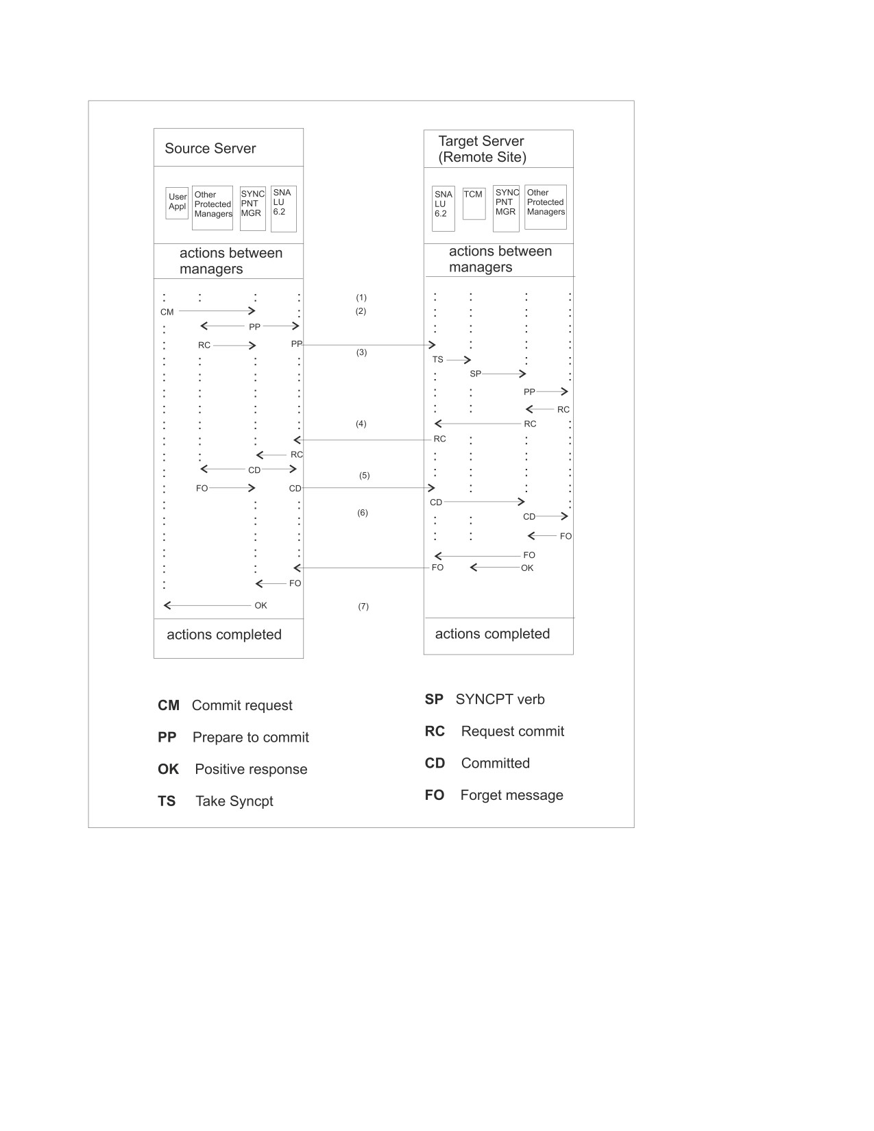
Figure 121. Successful Two-Phase Commit
Figure Notes:
(1)
The Target Communications Manager (TCM) issues a
RECEIVE_AND_WAIT APPC verb to receive the next SQL Request from
the Source Server.
(2)
The source application program requests the SYNCPNTMGR to commit
the logical unit of work (LUW). The source SYNCPNTMGR notifies the
SNA LU 6.2 communications facilities to prepare to commit and notifies
the source database (and other protected resource managers registered with
the SYNCPNTMGR) to prepare to commit. The source communications
326
System Administration
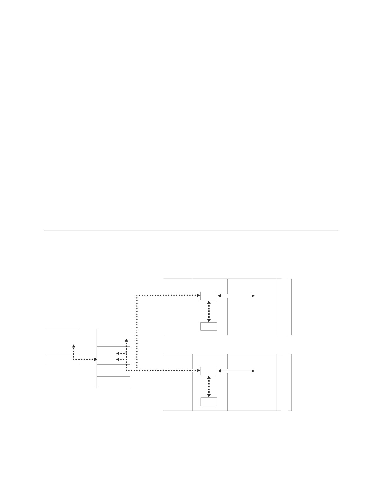
facility sends the SNA LU 6.2 prepare message to the target system. The
local protected resource managers respond to the source SYNCPNTMGR
with the ″Request Commit″ message.
(3)
On the target system, the RECEIVE_AND_WAIT verb is completed and the
WHAT_RECEIVED parameter is set to TAKE_SYNCPT.
The TCM issues a SYNCPT verb to the target SYNCPNTMGR which
begins the commit processing. The SYNCPNTMGR prepares the protected
resources to commit.
(4)
The SYNCPNTMGR sends the SNA LU 6.2 request commit message to the
source system.
(5)
The source SYNCPNTMGR collects the request commit messages from the
SNA LU 6.2 communications facilities and the other protected resource
managers. The source SYNCPNTMGR then commits the logical unit of
work by requesting that all of the resources commit. This causes an SNA
LU 6.2 committed message to be sent to the target system.
(6)
The target SYNCPNTMGR requests that the local resources commit the
logical unit of work and causes an SNA LU 6.2 forget message to be sent
to the source system. In addition, the target SYNCPNTMGR posts a
positive response to the TCM for the SYNCPT verb issued in note (3).
(7)
When the source SYNCPNTMGR receives the ″FO″ responses from the
protected resource managers, a positive response to the commit is given to
the application program.
CICS/VSE Syncpoint Manager and the Task Related User Exit (TRUE)
In the DRDA2 VSE environment, DB2 Server for VSE uses CICS/VSE as its sync
point manager. The environment can be shown as follows:
VSE / VSA 1
//
VTAM 1
CICS 1
DB2 for VSE
//
PC
Server 1
//
AXE
//
//
//
//
//
SPM
//
DB2
DRDA Sync
//
Application
Point Mgr
DDCS
//
DB2 CAE
V2.3.1
VTAM 2
CICS 2
DB2 for VSE
//
PC
Server 2
//
CM/2
AXE
//
//
OS/2
//
//
//
SPM
//
//
VSE / VSA 2
Figure 122. DB2
Server for VSE Distributed Unit of Work
This diagram shows how a workstation application might use DDCS for OS2
V2.3.1 to execute a distributed unit of work between 2 DB2 Server for VSE servers
Chapter 14. Using a DRDA Environment
327
on different VM/ESA systems. Notice that DDCS registers itself with its own sync
point manager. DDCS then establishes protected conversations with CICS AXE
transactions. Each AXE transaction registers itself with a locally installed
CICS/VSE sync point manager and CICS will perform any sync point logging and
resynchronization activity. The AXE transactions use the VSE XPCC protocol to
communicate with the DB2 Server for VSE servers 1 and 2.
DB2 Server for VSE also requires the use of a task-related user exit (TRUE) to
interface with the CICS/VSE syncpoint manager and with the DB2 Server for VSE
database manager as it participates in a coordinated commit or backout process.
This interface is described in the CICS/VSE Customization Guide.
A separate task-related user exit program is enabled and started for each DB2
Server for VSE application server in support of distributed unit of work (two-phase
commit). This is done by the AXE transaction under the following circumstances:
v DB2 Server for VSE database start-up parameter SYNCPNT=Y, and
v The conversation with the application requester is a protected basic conversation
(synclevel 2), and
v The application starts doing some work (for example, begins using an agent),
and
v The task-related user exit is not yet enabled.
The entry name of the task-related user exit program is ’ARI0xAXE’, where x is
0->9, A->Z. x is the last character of a DB2 Server for VSE application server
APPLID. The APPLID of a DB2 Server for VSE application server can be any of the
following reserved DBNAMES:
v SYSARI00 to SYSARI09,
v SYSARI0A to SYSARI0Z.
Therefore, the corresponding entry name of the task-related user exit program is
v ARI00AXE to ARI09AXE,
v ARI0AAXE to ARI0ZAXE.
CICS transactions for managing DRDA task-related user exits:
DAXP The DAXP transaction is a CICS transaction that sets the parameters that
will be used when an AXE transaction subsequently autostarts DRDA
TRUE (task-related user exit) support for an application server.
For more information on DAXP, see the DB2 Server for VSE & VM
Operation manual.
DAXT The DAXT transaction is a task-related user exit administration routine
that is responsible for disabling DRDA support within CICS/VSE. It issues
the EXEC CICS DISABLE command to disable a task-related user exit
program.
For more information on DAXT, see the DB2 Server for VSE & VM
Operation manual.
Managing In-Doubt LUW’s
Operator Commands
The following DB2 Server for VSE operator commands can be used to manage
in-doubt LUWs:
328
System Administration
SHOW ACTIVE
Displays the status of active agent structures1
SHOW CONNECT
Displays the status of all users or selected users connected to the
application server.
FORCE COMMIT
Heuristically forces an in-doubt LUW to COMMIT
FORCE ROLLBACK
Heuristically forces an LUW to ROLLBACK
SHOW INDOUBT
Displays the status of all DRDA2 distributed units of work that are:
v currently in-doubt
v were heuristically committed or rolled back but RESYNC has not yet
been performed nor has RESET INDOUBT been performed
v RESYNC failed for some in-doubt unit of work, because the status of the
LUW was the opposite of what RESYNC required. (for example,
RESYNC required that the unit of work be COMMITTED, but it had
been heuristically ROLLED BACK). At the same time, RESET INDOUBT
has not been performed.
RESET INDOUBT
Causes a heuristically committed or rolled back unit of work to be
forgotten by the database, (that is, causes a forget log record to be written.)
Making Heuristic Decisions
In a DRDA environment, resynchronization occurs if two-phase commit processing
is interrupted by a resource failure. However, the decision to commit or roll back
an in-doubt LUW by any way other than the normal resynchronization process is a
heuristic decision. If you commit or roll back a unit of work and your decision is
different from the other system’s decision, data inconsistency occurs. This type of
damage is called heuristic damage.
An example of heuristic damage would be if the operator performed a heuristic
commit and then the transaction manager requested that the unit of work be rolled
back. If this situation occurs, and your system then updates any data involved
with the previous unit of work, your data is corrupted and is difficult to correct.
The only way to correct heuristic damage is to restore the database from an archive
by manually correcting the data based on knowledge from the application. This
damage correction must be coordinated with all of the participating application
servers to ensure that the data is consistent in each individual application server
and between all of the participating application servers.
You can perform heuristic actions on in-doubt transactions that are not involved in
a distributed unit of work. The heuristic actions performed are not logged and
therefore are also not displayed by the SHOW INDOUBT operator command.
(Note that heuristic damage is still possible on these transactions.) See the DB2
Server for VSE & VM Operation manual for more information on the SHOW
INDOUBT command.
1. An agent is the internal database manager representation of an active user
Chapter 14. Using a DRDA Environment
329
Performing heuristic actions on distributed unit of work transactions must be done
with caution. You can use the FORCE command to perform heuristic functions on
distributed unit of work in-doubt LUWs when the resource owner cannot wait for
the sync point manager to perform the resynchronization action. See the DB2
Server for VSE & VM Operation manual for more information on the FORCE
command.
Resynchronization
Resynchronization occurs if two-phase commit processing is interrupted by a
resource failure. A resource failure may be caused by a node failure, a session
failure, a program failure or other problems by a protected resource manager. The
resource failure may be between a sync point manager and local resource
managers or sync point manager and remote resource managers.
Resynchronization is conducted independently for each failed protected resource
for which it is required. Resynchronization has the following purposes:
v To place distributed resources in consistent states, if possible; if not possible, to
notify the operator at the LU that detected the damage and at the LU of the root
of the sync point tree. The LU for DB2 Server for VSE is CICS/VSE.
v To unlock locked resources in order to free them for other uses
v To update the log showing that no more sync point work is needed for that
protected resource, for that LUW.
Resync When Partner is Not Active
After an LU failure, it is possible that the partner that is responsible for resync is
unable to establish the resync conversation because the failed LU has not been
restarted. The responsible LU retries the resync at implementation-defined
intervals.
In order to reduce the delay for resynchronization after an LU is restarted, the
partner LU may signal to the resync initiator that it is available by sending an
Exchange Log Names GDS variable that is not accompanied by a Compare States
GDS variable.2 Once the responsible LU has received this signal that the failed LU
is active, it can initiate resync, sending the Exchange Log Names and Compare
States GDS variables.
Sending the Exchange Log Names GDS variable as a signal of LU availability need
be done only once, no matter how many protected conversations require
resynchronization between the two LUs. Also, if the LU that becomes available is
responsible for initiating resync for some conversations, it need not send another
Exchange Log Names GDS variable as a signal that the LU is available, since the
partner SPM can infer that a partner is available from the other resyncs the partner
SPM initiates.
Resolution of In-doubts
In the VSE environment, resynchronization has two components:
2. The partner can tell that a Compare States GDS variable is not present because SPM’s RECEIVE_AND_WAIT verb will complete
with a WHAT_RECEIVED of SEND rather than DATA_COMPLETE.
330
System Administration