PowerWorld Simulator version 11. Manual - page 5
Series Capacitor Fields on Onelines
Series capacitor f ields are used to show field values specific to series capacitors.
Run Mode
If the Series Capacitor field for capacitor status is displayed, the capacitor status can be toggled in run mode when
you left-click on the field.
Right clicking on the series c apacitor field gives the option to display the Series Capacitor Field Dialog or the
Line/Transformer Information dialog.
Edit Mode
To enter a new series capacitor field, select Insert > Fields > Series Capacitor Field from the main menu or the
Series Capacitor Field button on the Insert Toolbar, and then click on or near the series capacitor object for which
you want to add the new field. This calls up the Series Capacitor Field Dialog. Enter the from and to bus numbers
associated with the device (the default values for these fields correspond to the series capacitor on which you
clicked), and the circuit number of the device. Enter the total number of digits that the field should display, as well
as the number of digits to the right of the decimal point. Finally, specify what the field should display: the capacitor
status or the series capacitance.
To modify the parameters of an existing series capacitor field, position the cursor anywhere on the object and right-
click to bring up the Series Capacitor Field Dialog. Use the Format > Display/Size main menu option to change
various display attributes for the series capacitor field, including its font and background color. Finally, you can use
the Format > Font option to change the font for selected fields on the display.
144
Building a Oneline Diagram
Switched Shunts
Switched Shunt Display Objects
Switched shunts are either capacitors that supply reactive power to the system or reactors that absorb reactive power.
Simulator represents switched shunts as a number of blocks of admittance that can be switched in a number of
discrete steps or over a continuous range. Switched shunt display objects come equipped with a circuit breaker that
indicates the shunt's status. If the switched shunt is closed, the circuit breaker appears as a filled red square. If the
switched shunt is open, the circuit breaker appears as a green square outline. To change the status of the switched
shunt, click the corresponding circuit breaker.
Switched shunt fields are often placed next to switched shunts to indicate the amount of reactive power supplied by
the device. For switched shunts with such a field, you can manually increase the reactive power supplied by the
device (provided its control mode is discrete) by clicking on the up-arrow associated with the device's reactive power
field. Likewise, you can decrease the reactive power supplied by the device by clicking on the down-arrow. To make
the up/down arrows visible, set the Delta per Mouse Click on the switched shunt field to a nonzero value.
Right-clicking on the switched shunt displays the Switched Shunt Dialog. Use the Switched Shunt Dialog to inspect or
modify the model of the switched shunt.
You can add a new switched shunt to the case in Edit Mode. Select Insert > Switched Shunt from the main menu, or
click the Switched Shunt button on the Insert Toolbar. Then click the bus where you would like to attach the device.
The Switched Shunt Dialog will appear. The bus number is automatically determined from the bus to which you
attached the capacitor. Enter the size, the thickness of the pen [in pixels] used to draw the device, and its orientation.
The Nominal Mvar field gives the amount of reactive power the device would supply if its terminal voltage were 1.0 per
unit. The Control Mode field determines whether the switched shunt has a fixed value or will vary discretely or
continuously within its operating limits to maintain its terminal voltage within the voltage range specified in the Voltage
Regulation field.
The amount of shunt admittance is specified in the Switched Shunt Blocks table. The columns in this field correspond
to different blocks of admittance. The first row indicates the number of steps in each block, and the second row gives
the amount of nominal Mvars per step. The switched shunts are always switched in the order specified in this field.
Select OK to add the device. If you do not want to add the switched shunt to the case, select Cancel.
To modify the parameters for an existing switched shunt, position the cursor on the device and right-click. This again
brings up the Switched Shunt Dialog. You can then change any parameter of the switched shunt. Choose Format >
Display Appearance from the main menu to change the color and/or line thickness.
To delete an existing switched shunt, use the Edit > Cut or Edit > Delete menu items.
145
Switched Shunt Fields on Onelines
Switched Shunt field objects are used primarily to indicate various quantities associated with switched shunt devices.
Furthermore, some switched shunt field types, which are distinguished by an integrated spin button, may be used to
change switched shunt device properties.
Run Mode
For switched shunt fields with an associated spin button, clicking on the up/down arrows will change the value of the
associated field.
Right clicking on a generator field gives you the option to open the Switched Shunt Field Dialog or the Switched
Shunt Information Dialog.
Edit Mode
Simulator offers two options for adding switched shunt fields to a oneline in Edit Mode. If you need to enter only a
single field, the easier approach may be to choose Insert > Field > Switched Shunt Field from the main menu or
the Switched Shunt Field button from the Insert Toolbar and then select the switched shunt to which you want to
add the field. This invokes the Switched Shunt Field Dialog. Enter the bus number associated with the device (the
default is the bus associated to the closest switched shunt to the field), the ID field, the total number of digits to
show, and the number of digits to the right of the decimal point. Next, select the type of field to show.
The second approach for adding new switched shunt fields entails right-clicking the bus and selecting Add New
Fields Around Switched Shunt from the resulting local menu. Please see Inserting and Placing Multiple Display
Fields for more details.
To modify the parameters of an existing swtched shunt field, position the cursor anywhere on the object and right-
click. This brings up the Switched Shunt Field Dialog. Choose Font > Line/Fill, or Font > Display/Size from the
Format menu to change various display attributes of the field, including its font and background color.
146
Building a Oneline Diagram
Interfaces
Interface Display Objects
Interface display objects are used on the onelines to visualize the flow of power through an interface record. Interface
records are used to show the net real power (MW) flow on a group consisting of one or more of the following devices:
1) transmission lines and/or transformers, 2) total tie-lines between two adjacent areas, and 3) total tie-lines between
two adjacent zones. Only area-area and zone-zone interface records can be displayed using interface display
objects.
Interfaces, like transmission lines, are represented as multi-segment lines, except that they may be drawn between
area/zone objects in addition to buses. Drawing interface display objects involves the same steps as drawing
transmission lines and transformers. The line thickness and color of interface objects may be customized by selecting
Format > Display/Size from the main menu.
Interface Fields and Interface Pie Charts are often placed close to or on the interface to indicate the power flow
through the device.
Run Mode
When animation is active, the flow of the arrows on the interface object may represent either the MW flow through
the interface or the currently calculated power transfer distribution factor (PTDF) pertaining to that interface. You
can customize the appearance of the animated flows using the Animated Flows Tab of the Oneline Display Options
Dialog available using the local menu.
Right-click on the interface to view the Interface Dialog for the interface.
Edit Mode
The quickest method of inserting new interface objects is to use the Options > Auto Insert Interfaces. Please see
Automatically Inserting Interfaces for details.
To manually add a new interface object to the case, first select Insert > Interface from the main menu, or click the
Interface button on the Insert Toolbar. Then place the cursor on the starting location for the interface (usually an
area/zone object or a bus object) and left-click. Add more segments to the interface by moving the cursor and the
left-clicking at the end of the segment. To finish adding an interface, place the cursor on the terminal object for the
interface and double-click. This then calls up the Interface Dialog. Either select an existing interface, or define a
new interface (see Interface Dialog for details).
Interfaces can be anchored to either area/zone objects or bus objects.
To change the shape of the interface, first left-click on the object to select it. This causes handles to appear at each
vertex. You can then move any vertex by dragging it with the left mouse button down. To remove a vertex, hold
down the CTRL key and then click the vertex you would like to delete. To add a vertex, hold down the CTRL key
and then click on the interface where you would like to add the vertex.
147
Automatically Inserting Interface Display Objects
The Automatic Insertion of Interfaces Dialog is used to automatically insert interface objects on the oneline diagram
between existing area/zone display objects. Interface pie chart objects can also be inserted as part of this process.
The automatic insertion of interface display objects greatly accelerates the construction of interface diagrams, which
are particularly useful for animating the results of PTDF calculations. Only area-area and zone-zone interface records
can be displayed using interface display objects.
The following procedure describes the quickest way to create an interface diagram for showing PTDF information and
area-area or zone-zone flows. It steps through the process from the creation of area-area or zone-zone interface
records to the addition of the area or zone display objects and, finally, to the automatic insertion of interface display
objects.
· Select Case Information > Interfaces from the main menu to bring up the Interfaces Display.
· Right-click on the Interface Records Display to show its local menu. Select Auto Insert Interfaces from the local
menu. This generates the Auto-Insert Interfaces Dialog.
· Use the Auto-Insert Interfaces Dialog to create the area-area or zone-zone interface records automatically.
At this point, the interface records have been created automatically. We now want to generate an interface diagram,
with the interface display objects added to it automatically.
· On a oneline diagram (either an already open diagram or a brand new one created by choosing File > New Oneline
from the main menu), place area/ zone objects at the desired locations.
· Select Insert > Auto Insert > Interfaces to display this dialog.
· Check the Insert Pie Charts on Interfaces box to automatically insert interface pie chart objects when the
interfaces are inserted. If this option is selected, change the Default Size of Interface Pie Charts to specify their
size.
· Select OK to insert the new oneline objects. New interface objects are automatically inserted between any
area/zone objects that have a corresponding interface record that is not already represented.
Note that you can do this automatic insertion as often as you like. The Number of Interfaces Not Shown field
indicates how many interfaces still need to be added to the diagram to represent all defined area-area or zone-zone
interfaces. It is a read-only field.
148
Building a Oneline Diagram
Interface Fields on Onelines
Interface field objects are used to show values associated with interface records.
Run Mode
Right clicking on the interface field displays the Interface Field Dialog.
Edit Mode
To enter a new interface field, select Insert > Field > Interface Field, and then click on the background of the
oneline diagram where you want the field placed. This calls up the Interface Field Dialog. Enter the name of the
interface, the total number of digits desired in the field, and the type of field.
To modify the parameters of an existing interface field, position the cursor anywhere on the object and right-click.
This again brings up the Interface Field Dialog. Use the Format > Font command to change the font (including its
color) used with the field. Use the Format > Line/Fill command to change the background color used for the field.
149
InterArea Flow Options Dialog
This dialog is outdated in PowerWorld Simulator version 5.0 and later. See help on the Interface Field Information
Dialog for the updated dialog.
When viewing an area diagram containing inter-area objects created using PowerWorld Simulator version 4.2 or older,
this dialog allows you to set text fields displaying either the actual or scheduled MW flow on the inter-area object.
150
Building a Oneline Diagram
Interface Pie Charts on Onelines
Interface pie charts are used to graphically show the percentage loading on an interface record. The amount of
shaded region of the pie chart indicates how close the interface is to its limit (provided the interface has a nonzero
limit). The appearance of the interface pie charts, including their color and the ability to automatically change size
based upon loading level, can be customized on the Oneline Display Options Dialog.
Right-clicking on the interface pie chart displays the Interface Pie Chart Dialog. This dialog can be used to customize
the size of the pie chart, or change the interface's limit.
Edit Mode
To enter a new interface pie chart, select Insert > Interface Pie Chart from the main menu or click the Interface
Flow Pie Chart button on the Insert Toolbar. Then, click the left mouse on the interface object with which you want
to associate the pie chart. This calls up the Interface Pie Chart Dialog, which is used to customize the appearance
of the pie chart.
151
Loading NERC Flowgates
This command reads flowgates from a text file and inserts them as interface records. The format for this file should be
similar to the file found at http://www.nerc.com/~oc/dfwg.html. To access this file you must have a NERC-supplied
username and password. At the time of writing we have not seen an official description of the format -- currently
Simulator just mimics the format found in this file. Flowgates are used by NERC (under Policy 9) as proxies for
transmission limitations and transmission service usage on the interconnected electric power network. Simulator
models flowgates using the interface records. Interface records MAY include contingency elements.
The Load NERC Flowgates option is available from the local menu of the Interface Records display.
152
Building a Oneline Diagram
Saving NERC Flowgates
This command writes all the interfaces to a text file using the NERC flowgate format. See the file found at
http://www.nerc.com/~oc/dfwg.html for an example of the NERC format. To access this file you must have a NERC-
supplied username and password.
The Save NERC Flowgates option is available from the Save As option of the local menu of the Interface Records
display.
153
Oneline Links
Links to Other Onelines
Run Mode
Oneline links are one of the mechanisms used in Simulator to allow you to view multiple oneline diagrams on the
same screen. By default, the oneline links are shown as blue rectangles surrounding a text identifier of the linked
oneline diagram. Double-clicking the left mouse button anywhere within the oneline link object will display the
linked oneline diagram, even if it has not already been opened.
The ability to associate multiple oneline diagrams with a single case may prove particularly helpful when dealing
with large cases. If a single oneline diagram is used to display a case having many buses, the diagram may
become cluttered, and it will be difficult to analyze the case in sufficient detail. The ability to associate additional
onelines with the case and to call up those additional onelines using one-links can significantly enhance your view
of the system.
Note that you can also use the File > Open Oneline command from the main menu to open any oneline diagram
(*.pwd) file directly. See Opening a Oneline Diagram for further details.
Edit Mode
To add a new oneline link to a oneline diagram, first select Insert > Oneline Link from the main menu, or select the
Link button on the Insert Toolbar. Then, click the left mouse button at the location where you would like to display
the new link. The Oneline Link Options Dialog box will open, asking you to enter the name of the file that stores the
linked oneline and a caption for the clickable oneline link object. Note that you can enter simply the name of the
oneline file in this location. Simulator will look in the same directory as the case file by default. However, you can
also specify additional directory locations to search for oneline diagrams by opening the Solution/Environment
Options, switching to the Oneline tab, and using the Edit Oneline Browsing Path option to add additional search
locations for oneline diagrams
To modify the parameters of an existing oneline link, position the cursor anywhere on the object and right-click.
This invokes the Oneline Link Options Dialog, allowing you to change the identity of the linked file and the caption.
Select Format > Display/Size from the main menu to modify various display attributes of the oneline link, including
font size and background color.
154
Building a Oneline Diagram
Document Links on Onelines
Just as you can link to other oneline displays from a oneline diagram using oneline link objects, you can also link to
documents and data on the world-wide web using Document Link Objects. When you click on Document Link Objects
in Run Mode, your system's default browser will be launched to retrieve the linked URL address. This feature is not
only for web URL's, though. Any file can be linked and its associated application will automatically open. This means
that power point files, word documents or spreadsheets can also be linked.
To add a Document link to a oneline diagram, select Insert > Document Link from the main menu. Then, click the
left mouse on the oneline diagram at the position where you would link to insert the Document link. The Document
Link Options Dialog box will appear, asking you to specify the world-wide web address to which to link as well as a
clickable caption to display on the oneline diagram. Enter the requested information and press OK to add the
Document link object to the oneline.
To modify the caption or address for a Document link object, right-click anywhere on its text. Specify its new
parameters in the Document Link Options Dialog and press OK. You may also modify various aspects of its
appearance, including the font size, by choosing Format > Display/Size from the main menu.
Note that Document links are active only in Run Mode. Clicking on a Document link object from the Edit Mode will
have no effect other than to select the object for placement, formatting, etc.
155
Background Objects and Text
Background Lines on Onelines
The background of an oneline diagram can display added lines, polylines, and filled polygons among other items.
Edit Mode
To add a new background line, first select Insert > Background Graphic > Background Line from the main menu
or click the Background Line button on the Insert Toolbar. To draw a series of straight line segments on the
background, follow these steps:
· Position the mouse cursor where you want the series to begin and click and release the left mouse button.
· Move the mouse to the desired termination point of the first line segment. A straight segment will follow your
mouse movements. Click and release the left mouse button to complete the line segment and prepare for
drawing the next line segment, or double-click if this line segment is the last segment you wish to draw.
To draw a freehand shape rather than a series of straight line segments, click and hold the left mouse button where
you would like the freehand shape to begin and drag the mouse to trace the shape you desire (while holding the left
mouse button down). Release the left mouse button to complete the section of the freehand shape you have been
drawing. At this point, you can add either another freehand section or a straight line segment. When you have
finished drawing in the background, double click the mouse button.
Note that background display objects composed of straight line segments display significantly faster than lines
drawn freehand. Lines draw freehand (holding down mouse button) leave a vertex point at every point on the
screen, where a line composed of straight-line segments (left-clicking only where you want a vertex point) takes
considerably less effort for the PC to draw.
Use the Format > Display/Size command to change the color, line thickness and fill color associated with the line.
If the Use Background Fill option on the Line/Fill Tab of the Edit Multiple Objects Dialog is checked, the line is
assumed to be a polygon, with a line automatically drawn between the first point on the line and the last point. The
polygon is filled using the color specified in the Fill Color Field.
To change the shape of the line, first left-click on the line to select it. This causes handles to appear at each vertex.
You can then move any vertex by holding the left mouse button down and dragging the vertex to a new location. To
remove a vertex, hold down the CTRL key and then click the vertex you would like to delete. To add a vertex, hold
down the CTRL key and then click on the line where you would like to add a vertex. Note that freehand lines are
nothing more than a continuous series of vertices.
156
Building a Oneline Diagram
Background Rectangles on Onelines
The background of an oneline diagram can display rectangles among other items.
Edit Mode
To add a new rectangle, first select Insert > Background Graphic > Background Rectangle from the main menu.
Position the cursor where you would like to place the upper left-hand corner of the rectangle and click with the left
mouse button. A rectangle having the default size is inserted. Drag the rectangle's resizing handles to
resize/reshape the rectangle.
To resize or reshape an existing rectangle, click on it to select it. The resizing handles will appear, which you can
then drag to reshape or resize the rectangle.
To change the color, line thickness or fill color of the rectangle, first select it by clicking on it and then choose
Format > Display/Size from the main menu.
157
Background Ellipses on Onelines
The background of a oneline diagram can display ellipses among other items.
Edit Mode
To add a new ellipse, first select Insert > Background Graphic > Background Ellipse from the main menu, or
click the Background Ellipse button on the Insert Toolbar. Then position the cursor where you would like to place
the upper left-hand corner of the ellipse and click with the lef t mouse button. An ellipse having the default size and
shape is inserted. Drag the ellipse's resizing handles to resize/reshape it.
To resize or reshape an existing ellipse, click on it to select it. The resizing handles will appear, which you can then
drag to reshape or resize the ellipse.
Select Format > Display/Size from the main menu to change the color, line thickness and fill color of the ellipse.
158
Building a Oneline Diagram
Background Pictures on Onelines
The background of an oneline diagram can display a variety of objects, including lines, filled polygons, and even
pictures. The latter will be discussed in this section.
Edit Mode
Simulator can insert bitmaps, jpegs, enhanced and standard metafiles, and icons from files into the oneline
diagram. These pictures may either serve as a background or appear above other objects on the oneline.
To add a picture object to the oneline diagram, select Insert > Background Graphic > Picture from the main
menu. Then, click the oneline diagram at the point where you would like the top left corner of the graphic to be
placed. The Open Picture Dialog will open, asking you to select the graphic file that you want to insert. When you
select a file from the dialog, the dialog displays a preview image so that you can be sure that you are selecting the
right file. When you have identified the file to insert, click OK. The image will then appear on the oneline. It may be
resized by dragging its resizing handles.
By default, pictures are inserted at the middle stack level. Thus, they hide most other oneline display objects. To
change the stack level of the picture, click it to select it, and then select Format > Display/Size from the main
menu. From the Line/Fill Tab , select the stack level of your choice. The Base stack level places the picture below
all other oneline display objects, while the Top stack level will cause the picture to obscure all other display objects.
To resize or reshape an existing picture object, click on it to select it and then drag its resizing handles. To change
the stack level of an existing picture object, click on it to select it and then select Format > Display/Size from the
main menu for access to the Line/Fill Tab , from which you can modify the picture's stack level.
159
Converting Background Lines
Background lines can be converted to other objects by splitting, merging, or converting to power system objects. To
convert a background line, click with the right mouse button on a selected background line and the local menu will be
displayed with the conversion options. Most options are available if only a single background line has been selected
and no other objects are selected. The following options are available for converting a background line:
Split Background Line
A background line can be split at a vertex or anywhere along the line. Click the point on the line where the split
should be made and then click with the right mouse button and select the Split Background Line… option from the
local menu. Two background lines will result. This option is available only if exactly one background line has been
selected and no other objects have been selected.
Merge Background Lines
This option is only available if exactly two background lines have been selected. The two selected background lines
will be merged at the two closest ends and a single background line will result.
Convert to ac Transmission Line
After selecting this option, the Line/Transformer Information dialog will be displayed. The dialog options can be set
the same as they would be set when inserting an ac transmission line from the Insert menu. This option is available
only if exactly one background line has been selected and no other objects have been selected.
Convert to Bus
After selecting this option, the Bus Information Dialog will be displayed. The dialog options can be set the same as
they would be set when inserting a bus from the Insert menu. This option is available only if exactly one
background line has been selected and no other objects have been selected.
Convert to Substation
After selecting this option, the Substation Information Dialog will be display. The dialog options can be set the same
as they would be set when inserting a substation from the Insert menu. This option is available only if exactly one
background line has been selected and no other objects have been selected.
160
Building a Oneline Diagram
Oneline Text Fields
The Oneline Text Fields are fields that can be placed on an oneline diagram that display values specific to the current
display of the diagram, such as x and y coordinate of the mouse cursor, animation rate, zoom percentage, and x and y
coordinate of the center of the diagram at the center of the screen. These fields can be inserted on a oneline diagram
by choosing Insert > Field > Oneline Field.
161
Text on Onelines
Text display objects are used to show single lines of text on the oneline.
Edit Mode
To add descriptive text to the oneline, selec t Insert > Text from the main menu and click the oneline where you
would like the text to appear. The Text Options Dialog will open, asking you to enter the desired text string, and the
angle at which the text is to appear on the oneline diagram.
To modify an existing text object, position the cursor anywhere on the text and right-click. The New Text Options
Dialog will appear, allowing you to edit the text. Use the Format > Display/Size menu option to control the font and
background color of the text object.
162
Building a Oneline Diagram
Generic Model Fields
The Generic Model Fields are fields that can be placed on an oneline diagram that display any value for any object in
the case on the diagram. These fields can be inserted on an oneline diagram by choosing Insert > Field > Generic
Model Field.
This type of field comes in handy when you want to place a variety of fields on the diagram, without inserting specific
object-type fields. All fields of data are available in one location for placement on a diagram.
163
Edit Mode Tools and Options
Chapter 5: Edit Mode Tools and Options
Edit Mode provides a number of commands for customizing and modifying the case that are different from Run Mode.
This chapter covers the following:
· General Edit Mode Tools
· Insertion Using Palettes
· Automatic Object Insertion
· Equivalencing
· System Scaling
· Facility Analysis
165
General Tools
Appending a Case
The Append Case command allows you to append additional power system components to an existing case. Unlike
the Open Case command, Append Case does not delete the existing case (if any) before loading the selected case.
To append a case to the existing case, select Tools > Append Case in Edit Mode.
The Append Case command can be useful when used in conjunction with the Equivalencing Display.
Notes
Appended data completely overwrites an existing record corresponding to the same bus number(s).
Branch elements are appended to a case only if both of their terminal buses exist.
166
Edit Mode Tools and Options
Refresh Anchors
The Refresh Anchors option of the Edit Mode Options/Tools menu allows you to update or reset the anchoring of
objects on an oneline diagram to their respective anchor. When building oneline diagrams and adding several new
devices, it can sometimes be advantageous to use the Refresh Anchors option when finished to ensure the anchoring
of objects to the appropriate anchor on the finished oneline diagram.
167
Bus Renumbering Dialog
The Renumber Buses Display allows you to change the bus numbers for either the entire power system case, and/or
for any open oneline diagrams. To show this display, select Tools > Renumber Buses.
The bus renumbering feature is provided because it is sometimes necessary to renumber buses in the power system
model, either to make room for new buses or to move buses to a different zone or area that has a different numbering
scheme. It may also be necessary to renumber bus display objects on the oneline if you want to use the oneline with
a case other than the one for which it was originally designed. The bus-renumbering feature provides a convenient
way of accomplishing this.
The table at the bottom of the Bus Renumbering Dialog is used to manage the lists of current bus numbers and any
desired changes to the numbering scheme. You can specify the bus numbers to change and their new values by
directly typing them into the table. Alternatively, you can generate the bus list automatically by selecting one of the
Automatic Setup of Bus List Options and clicking the Setup Bus Swap List button. The Automatic Setup options
allow you to add to the list all buses in the case, all buses in the case subject to the area/zone/owner filter constraints,
all buses currently displayed on the oneline, or a set of numbers from a text file.
The table behaves just like a Case Information Display and thus has a local menu that can be invoked by clicking the
right mouse button. Select Insert from the local menu to insert a new bus number to change, or select Delete to
delete a bus number that is currently in the list. Select Show Dialog to display the Bus Information Dialog
corresponding to the bus number on which you right-clicked. You may clear the entire list by pressing the Clear Bus
List button.
Once you have indicated which buses you would like to renumber in the table, select an option from Bus Change
Options to specify where you would like to implement the changes (in both the case and the oneline, in the case only,
or in the oneline only). Make the changes by pressing the Change Bus Numbers button. Close the dialog by
pressing Close.
The option groups at the top of the dialog deserve further discussion. See Bus Renumbering Options for further
details or click NEXT.
168
Edit Mode Tools and Options
Bus Renumbering: Automatic Setup of Bus List Options
This section of the Bus Renumbering Dialog is used to generate automatically a list of the buses to be renumbered.
Select an option from the list and click on the Setup Bus Swap List button to generate the list, or Clear Bus Swap
List to clear the list.
Load All Buses in Cases
Creates entries in the table for every bus in the system. By default the new bus number is the same as the old bus
number. Of course you do not have to renumber every bus. If you would like a bus to keep its same number, either
add that bus to the table, or simply have an entry with the old and new bus numbers identical.
Load Buses with Valid Area/Zone Filters
Same as the Load All Buses In Case option except only those buses with valid area/zone/owner filters are added.
This allows you to easily modify the bus numbers in just an area or zone.
Load Only Buses on Oneline
Creates entries in the table only for those buses on the current oneline. This option is most useful when you are
just changing the buses on the onelines.
Load Buses From Text File
Creates entries in the table using an external text file. The format of this file is as follows:
1
11
Specifies converting from old bus number 1 to new bus number 11
2
22
Specifies converting from old bus number 2 to new bus number 22
etc.
Freshen Current Oneline
The Freshen Buses option is designed to help you quickly renumber an existing oneline to work with a new
numbering scheme. You will find this method helpful if you have been using the oneline with a case and now must
use it with a different case having a different set of bus numbers, but the same bus names. Freshen Buses will try to
match the buses on the oneline with the buses in the new case by matching bus names and kv, rather than by
number (which is how Simulator usually tries to link bus display objects with bus records in the case). The best way
to learn how to use Freshen Buses is to consider the following example:
To update an old oneline to work with a new bus numbering scheme:
· Open the oneline and the old case with which it was used.
· Choose Options/Renumber Buses from the edit-mode menu.
· Select "Load Only Buses on Oneline" and press the "Set up Bus Swap List" button.
· Change the "Swap?" field values all to Yes.
· Right click on the table and choose Save List to File. Give the file a name. For this example, we'll name the file
"oldscheme.txt." This file will contain the list of buses represented on the oneline, specifying each bus's
number, name, kv, and area.
· Close the old case.
· Open the new case and the oneline you wish to renumber. If any other onelines open with the case, close
them. You w ant only the oneline you wish to renumber to be shown.
· Choose Options/Renumber Buses from the edit-mode menu.
· Select "Freshen Current Oneline" and specify the file "oldscheme.txt" (for this example). Click the "Set up
Swap List" button. Simulator will match the old numbering scheme used in the oneline with elements in the new
case by name and kv. If it finds more than one match, it will use the element's area name as a tie breaker. If it
still can't reconcile the multiple matches, it will add both renumbering options to the table.
· Go through the new list and make sure that you want to swap the buses that are listed. If you do, change the
"Swap?" field value for each to Yes (you can do this quickly for all buses by right-clicking on the Swap? column
and choosing "Toggle All Yes." Be sure to reconcile any duplicate bus renumbering suggestions. These are
cases for which Simulator could not determine how to renumber the buses a bus on the diagram matches more
than one bus in the case by name, kv, and area.
· Click the Change Bus Numbers button at the bottom of the form.
169
Once the oneline has been renumbered, save it with the case by selecting File / Save (or File / Save As if you wish
to give it a different name) from the main menu. See Bus Change Options for additional details.
170
Edit Mode Tools and Options
Bus Renumbering: Bus Change Options
This option is used to specify which buses to change.
Change Both Case and Onelines (default)
Renumbers the buses in both the case and any open oneline diagrams.
Change Only Case
Only renumbers the buses in the case. The oneline bus numbers are not changed.
Change Only Onelines
Only renumbers the buses on the onelines. The case itself is not changed. You would want to select this option if
you have already changed the case (or loaded a different one), but now have several onelines based on that case
that also need to be changed. See Automatic Setup of Bus List Options for more details. This is the most
commonly used option.
171
Merging Buses
Two or more buses can be merged to a new bus in "Edit Mode" with the loads, generators, and shunts of the buses
merged moved to the new bus. The transmission lines among the buses merged will be deleted while the transmission
lines connecting the merged buses and buses which are not selected to merge will be moved to the new bus.
To join two or more buses together, select at least two power system elements (at least one of them being a bus), then
right click to invoke the one-line popup menu and select Merge selected buses. Specify the buses to merge further if
needed by clicking Add and/or Delete button. To add buses to merge, click Add and select all the needed buses in
the Choose a Bus dialog and click OK. To delete from already selected buses, select the buses to delete and click
the Delete button.
Once you have the elements to merge selected, enter the number, name, nominal voltage, zone number, area number
and substation number for the new bus. These properties can be set to be the same as one of buses to merge by
selecting it in the Specify buses to merge box and pressing the Set new bus properties same as selected bus .
Buses can also be merged in the Bus Records case information display. To do so, select a cell and right click to popup
the local menu. Select Merge selected buses which is the third item in the second group. The buses to merge and
the properties of the new bus can be edited in the Bus Merging Dialog.
When buses are merged from the one-line diagram, the selected buses will be joined in both the PWB case and the
one-line. When buses are merged from the bus grid, the selected buses will be joined only in the PWB case but not in
the one-line. This might result in bus objects not connected to bus records in the one-line.
172
Edit Mode Tools and Options
Splitting Buses
Simulator assists you in transforming one bus into two connected buses. This process is called splitting a bus. In
performing the split, the user is able to decide which equipment to keep connected to the original bus and which
equipment to move to the new bus. Because this activity impacts the structure of the power flow equations, bus
splitting can be performed only in Edit Mode.
To split a bus from the oneline diagram, right click on the bus you wish to split, and click Split from the resulting local
menu. To split a bus from the Bus Case Information Display, right-click on its corresponding record and again click
Split from the resulting local menu. In either case, the Bus Split Dialog will appear.
Multi-section lines merit special consideration during bus split operations. These are the rules Simulator follows when
you try to split a bus that is part of a multi-section line. If the original bus is the endpoint bus of a multi-section line and
the ending line segment was transferred to the new bus, then the new bus becomes the new ending terminal of the
multi-section line. If the original bus was a dummy bus of the multi-section line, and if exactly one of the branches
connected to the original bus is rerouted to the new bus, then both the new bus and the original bus will be dummy
buses in the reconstituted multi-section line. If neither or both of the lines connected to the original dummy bus were
rerouted to the new bus, then the multi-section line definition is eliminated, since Simulator has no way to determine
how the multi-section line should be redefined.
A final consideration involving bus splits is how sequence data is treated. If you have defined sequence data for fault
analysis, Simulator will recalculate the sequence data for the original and new buses after the split. In this case, the
zero sequence impedance for the new branch that connects the original and the new bus will be set to j0.0001.
173
Split Bus Dialog
The Split Bus dialog contains two sections labeled Existing Bus and New Bus . These sections enable you to
designate the bus you want to split and the name and number of the new bus created by the bus split operation. If you
opened the Split Bus Dialog from either the Bus Case Information Display or an oneline diagram, the Existing Bus
Name and Number fields will be read-only and will identify the bus you selected. How ever, if you opened the Split Bus
Dialog from Simulator’s main menu, you will first have to choose a bus to split. In this case, use the Find… speed
button located next to the Existing Bus label to select the bus to split, or simply type its number in the Existing Bus
Number field. Then, provide the name and number for the new bus to create using the New Bus Name and Name
fields. The number you specify in the New Bus Number field must be unique; it cannot be a number that identifies
another bus in the case. If you do specify an existing number, Simulator will issue an error message and require you
to specify a different number. If you choose not to specify a name for the new bus, Simulator will set the name of the
new bus to be the same as the bus’s number.
Once you have identified the bus to split and the name and number for the new bus resulting from the split, you may
then specify whether a bus tie should be inserted between the existing bus and the soon-to-be-created new bus. By
checking the Insert bus tie between existing and new buses checkbox, you command Simulator to place a very
low -impedance bus tie between the bus to split and its offspring. The new branch will have an impedance of 0.0000 +
j0.0001 ohms. If the bus tie should be inserted as an open branch, check the Normally open checkbox. This option
becomes available, of course, only if you elect to have Simulator automatically add the new bus tie.
After you have finished making your selections, click OK. Simulator will create the new bus, assign its electrical
attributes to match those of the existing bus, and add the bus to the power system model. If a oneline diagram is
currently active and the existing bus is represented on it, Simulator will add a symbol for the new bus to the diagram,
placing it immediately to the right of the existing bus’s symbol. If you elected to create a bus tie between the existing
and new buses, Simulator will also add a symbol for the bus tie to the diagram.
Finally, Simulator will automatically open the Equipment Mover Dialog to help you manage the transfer of equipment
from the existing bus to the new bus.
174
Edit Mode Tools and Options
Equipment Mover
Simulator provides a convenient tool for transferring equipment between buses. Simulator allows you to move bus
shunts, loads, generators, switched shunts, and transmission lines between buses. For loads, generators, and both
varieties of shunts, Simulator offers you the ability to transfer all or part of the equipment from the origin bus to the
destination bus.
Equipment may be transferred between buses using the Equipment Mover Dialog. The Equipment Mover Dialog can
be opened in any of four ways:
· From the main menu, choose Options / Tools > Move Bus Equipment …
· Right click on the bus from which you want to move equipment and select Move Equipment… from the resulting
local menu.
· From a Bus Case Information Display, right-click on the record corresponding to the bus from which you want to
move equipment and select Move Equipment … from the resulting local menu.
· As the final step of the Bus Split operation.
Regardless of the approach you take, Simulator will then open the Equipment Mover Dialog. The Equipment Mover
Dialog consists of three sections. The top portion of the dialog is split in two sections that identify the bus from which
equipment will be transferred (on the left) and the bus equipment w ill be transferred to (on the right). If the dialog was
opened as the final operation of the Bus Split operation, these two buses will be hard-coded to identify the original bus
and the bus resulting from the split. If the dialog was opened from the main menu, you must select both the origin and
destination buses from lists that are reminiscent of case information displays. If the dialog was opened using one of
the other two methods, the origin bus will be set to the bus you selected, and you will then have to choose the
destination bus. To select a bus to be an origin or destination bus, simply select the corresponding record from the
appropriate list.
Once the origin and destination buses have been identified, you must then select the equipment to transfer from the
origin to the destination bus using the case information display that occupies the bottom of the dialog. To move a
particular piece of equipment, toggle the value of the Move Object? field to YES. To move just portions of loads,
generators, or shunts from the origin to the destination bus, adjust the value of the Move % field from 100.0 to the
percentage you desire.
Once you have selected the equipment you wish to transfer, click the Move equipment button. Simulator will adjust
the power system model to reflect your equipment transfer requests. Furthermore, Simulator will provide you an
opportunity to manually adjust all open oneline diagrams to reflect the equipment transfers. To facilitate this activity,
Simulator will open a Potential Misplacements Dialog for each oneline that displays the origin bus. The Potential
Misplacements Dialog lists the display objects associated with the equipment that had just been transferred from the
origin to the destination bus. By clicking on an entry in this list, you can pan the associated oneline diagram to focus
on that object. This allows you to identify display objects that perhaps should be relocated to reflect their new bus
associations. Once you have finished addressing these potentially misplaced display objects, click the OK button to
close the Potential Misplacements Dialog.
If you find that you would like to reopen the Potential Misplacements Dialog after you have closed it, click the List
most recent transfers button. This will reopen the Potential Misplacements Dialog associated with the most recent
equipment transfer operation.
To conclude the equipment transfer operation, click the Close button.
175
Potential Misplacements Dialog
In the wake of an equipment transfer operation using the Equipment Mover Dialog, some oneline display objects may
be out of place. To ease the task of correcting these misplacements, Simulator provides the Potential Misplacements
Dialog. Simulator opens a Potential Misplacements Dialog for each oneline that displays the bus that served as the
origin for equipment transfer. The Potential Misplacements Dialog lists the display objects associated with the
equipment that had just been transferred from the origin to the destination bus. By clicking on an entry in this list, you
can pan the associated oneline diagram to focus on that object. This allows you to identify display objects that
perhaps should be relocated to reflect their new bus associations. Once you have finished addressing these
potentially misplaced display objects, click the OK button to close the Potential Misplacements Dialog.
176
Edit Mode Tools and Options
Tapping Transmission Lines
Simulator eases the process of inserting a bus at some location along an existing transmission line. This feature can
be extremely useful when you want to add a new generation site to a model, for example. Rather than having to
delete an existing line, place the bus, and draw two new transmission lines, Simulator simplifies the task to a one-step
process.
A line can be tapped from a oneline diagram, the transmission line case information display, or by choosing Tap
Transmission Line from the Tools menu. From the oneline diagram, right-click on a transmission line and select
Insert Line Tap from the popup menu. From the case information display, simply right-click on the corresponding
branch record and select Tap Transmission Line from the popup menu. Either of these methods will open the
Automatic Line Tap dialog for setting up and inserting the new bus.
Note that transmission lines may be split only from Edit Mode. You cannot access this functionality from Run Mode.
177
Automatic Line Tap Dialog
The Automatic Line Tap Dialog will allow you to define the settings to use for inserting a new bus along a transmission
line. The transmission line to tap will be represented in the panel at the top of the dialog, displayed as a Near Bus and
Far Bus. If the Automatic Line Tap Dialog was opened by right-clicking a line on a oneline diagram, or by right-clicking
on a record in the case information display, the line will already be selected in the panel. You can change the line
selection by first choosing the Near Bus you desire, and then selecting the Far Bus from the list of possible
connections to the chosen Near Bus. Note that the percentage entered in the Position along line field will be in
relation to the selected Near Bus. The inserted bus and new sections of the tapped line will adhere to the following
settings:
Position along line
The field labeled Position along line will indicate the point where you right-clicked the mouse relative to the
location of the nearest of the two buses to the mouse-click in terms of a percentage of the total line length. In other
words, if the line is 10 units long, and you clicked the right mouse at location 7 units from one end of the line, the
Position along line will indicate 30% from the bus at the other end of the line, identified on the display as the Near
Bus. If you opened the Automatic Line Tap Dialog from the case information display or the Tools menu, the
Position along Line will be set to 50%. In either case, you can adjust this setting to place the new bus more
precisely. The placement of the new bus controls how the impedances of the new lines are set, as the impedance
of each section will equal the section’s corresponding percentage length multiplied by the impedance of the original
line. Note that the original charging capacitance of the line will be reassigned as determined by the selection under
the Shunt Model option.
New Bus Number
By default, Simulator will find and set an unused bus number for you, but you can specify the number to be used for
the new bus, between 1 and 99999. If you enter a bus number that already exists, you will be prompted to enter a
different number when you click the Tap button.
New Bus Name
Specify a name to be assigned to the new bus. By default this field is blank, and if left blank Simulator will set the
name of the bus the same as the new bus number.
New Bus Area
You can specify the area for the new bus to be the same as the Near Bus , the Far Bus , or another value of your
specification. If you select the Specify option, the edit box and find button will become enabled. You can then
enter an area number manually, or click Find to locate an area from the list of areas currently in the case. If you
want a new area to be assigned to the case for this bus, simply enter an unused area number manually in the box,
and Simulator will automatically set up the new area record for the case. You can then open the Area Information
Display and set the name and other values for the new area.
New Bus Zone
You can specify the zone for the new bus to be the same as the Near Bus, the Far Bus , or another zone of your
specification. If you select the Specify option, the edit box and find button will become enabled. You can then
enter a zone number manually, or click Find to locate a zone from the list of zones currently in the case. If you
want a new zone to be assigned to the case for this bus, simply enter an unused zone number manually in the box,
and Simulator will automatically set up the new zone record for the case. You can then open the Zone Information
Display and set the name and other values for the new Zone.
Shunt Model
By default, Simulator will reassign the original charging capacitance as line shunts at the original terminal bus ends
of the two new line segments. The charging capacitance of the two new branch elements will be set to 0. This will
result in an exact match of power flows before and after the line tap.
Alternatively, you can choose to have the capacitance converted approximately using percentage entered as the
Position along line. In other words, the original capacitance will be scaled and assigned to the two new segments
as charging capacitance. This will result in a slightly different power flow result after the line tap, as it is an
approximation of charging capacitance on the two new segments.
Treat sections as a multi-section line
Check the box labeled Treat sections as a multi-section line to force the status of the two new line sections to be
controlled in unison.
Click the Tap button to close the Automatic Line Tap Dialog and perform the line tap. If a value on the dialog is not set
properly, a warning message will appear, and you will need to either change the specified value or cancel the process.
178
Edit Mode Tools and Options
Setting Default Drawing Options
The Default Drawing Options Dialog is used to define the default sizes of new display objects, as well as various other
display parameters. These options are available only from Edit Mode. To open the Default Drawing Values Dialog,
select the menu option Options > Default Drawing Values in Edit Mode.
The Default Drawing Values Dialog is organized using tabs showing the types of objects that can be added to
onelines. Each type of object has a table which describes the defaults available for that object.
Generally, the Default Drawing Values apply when you insert new objects on an oneline diagram. Changing the
Default Drawing Values does not automatically affect the existing objects already drawn on the diagram. However,
you can select multiple objects on a oneline diagram, and right-click on any one object to invoke the object's popup
menu. You will find the option Apply Default Draw Values, which will modify the formatting of the selected objects to
meet the default drawing value specifications.
Variable Defaults depending on Voltage Level
Many kinds of objects can have more than one set of defaults specified depending on their voltage level. When
more than one set of defaults is specified, the table is always sorted by Nom KV.
A new object is inserted with properties corresponding to the default with the lowest Nom KV that the object's
nominal KV is larger than. If the object's nominal KV is smaller than all defaults, then it will be set according to the
default with the lowest nominal KV.
For instance, assume 4 sets of defaults are defined for buses roughly as follows
Nom KV
Size
>400
15
>300
10
>200
8
>100
5
A new bus with nominal voltage of 345 kV is inserted with size 10.
A new bus with nominal voltage of 299 kV is inserted with size 8.
A new bus with nominal voltage of 69 kV is inserted with size 5.
In order to add another set of defaults for a kind of object, right-click on the table and choose Insert from the local
menu. In order to delete a set of defaults, right-click on the table and choose Delete. Once you have inserted a
new default, specify the new Nom KV for the default along with the new defaults.
Notes: When you c hange the Nom KV of a default, the list always sorts itself according to Nom KV. Insert will not
be enabled in the local menu for objects that can not have more than one set of defaults. Delete will not be enabled
if only one set of defaults is defined.
Modifying Values in the Default Drawing Values Dialog
The font colors in tables of this dialog follow the conventions of the Case Information Displays. Most default values
are enterable and can be modified by selecting the value you want to change and then typing in the new value.
Other values are toggleable and can be changed by double-clicking on the value. For reference regarding what the
various "size" defaults mean, when the zoom level is at its nominal value (100%), the size of the screen is 100 by
100. There are also some special kinds of fields in this dialog which are discussed next.
Editing Colors and KV-Based Color Coding
In order to modify a color value, double-click on the colored rectangle to bring up the Color Dialog. Then specify the
color you want. For some defaults, such as fill color, it is possible to specify the default color to be "none". In order
to set a color default to "none", select the colored rectangle and press the Delete key.
At times, a user may want to see the kV level of screen objects directly from the oneline diagam, without having to
open a text display. One way to do this is to color code the elements on the oneline diagram according to kV level.
Right-click on the table and choose Insert from the local menu. Specify the Nom kV and color.
Editing Default Field Positions ("Pos1", "Pos2", etc…)
Many objects allow you to specify some default fields to be automatically added when a new object is drawn. For
example, you may want to insert the bus name next to all new Bus Objects. In order to specify these defaults, click
on the table row corresponding to defaults you are interested in. Then click on the Show Field Positions button.
This brings up the Positions for Adding New Fields Dialog and will show you the present settings for new fields.
Positions that have a default specified will be highlights and the name of the default field will be shown. Positions
with no default field will not be highlighted and will say "Pos1", "Pos2", etc…. For objects that have more than one
possible orientation (e.g. generators can be up, right, left or down), the Adding New Fields Dialog will show
positions for each orientation.
179
In order to modify the settings, move your mouse over the position on the dialog you want to change and click. This
will bring up the appropriate Field Options Dialog such as the Bus Field Options, Generator Field Options, Load
Field Options, Switched Shunt Field Options, Line Field Options, Interface Field Options, Substation Field Options,
Area Field Options, Super Area Field Options, or the Zone Field Options. Simply select the field you want and
choose OK. If you would like to set a default field to "none", click Remove Field instead of OK. You can also
modify default fields by double-clicking on the table for "Pos1", "Pos2", etc… This brings up the appropriate Field
Options Dialog as well. If you press the Delete key while on a "Pos" field in the table, it will set the default field to
"none".
Note that as you navigate through the tabs on this Default Drawing Values Dialog, the Positions for Adding New
Fields Dialog will update to show you the default for the present object and voltage level you have selected.
Editing Stub Size and Stub Space
When utilizing the Automatically Insert Transmission Lines feature, the Stub Size and Stub Space values are used.
Simulator will draw each automatically inserted branch such that it emerges from both its terminal buses at right
angles. To accomplish this, Simulator draws each automatically inserted branch in three segments: two stubs
perpendicular to the terminal buses having a length specified by the value supplied for Stub Size, and a third
segment joining the two stubs. The amount of space between lines as the converge into a bus is set by Stub
Space .
If you do not want transmission line stubs to be inserted, then set Stub Size to 'none' or to a negative number. Note
in order to set a value for Stub Space , Stub Size must be set to a positive number first.
Editing CB Size
When you insert new transmission lines or transformers, circuit breakers will automatically be inserted on the
branch with their size specified by CB Size. If you do not want Circuit Breakers inserted for a particular voltage
level, then set CB Size to 'none' or a negative number.
Editing Pie Size
When you insert new transmission lines or transformers, pie charts will automatically be inserted on the branch with
their size specified by Pie Size. If you do not want pie charts inserted for a particular voltage level, then set Pie Size
to 'none' or a negative number.
Set Default Font
Click on this button to set the default font used for new text fields. This is the font which will be used for all new text
fields. Note however that the default font size set using this dialog is not used unless the option Use the default
font size for new text objects is selected. Otherwise, the specific kind of object and voltage level specifies what
the font size should be. For example, in the Interface tab, one of the defaults is Font Size. New Interface Fields will
use this font size.
Only Cut/Copy Display Objects, Not Power System Records
When you cut or delete an object from the oneline, Simulator needs to know whether you simply want to delete the
display object from the oneline or to purge the definition of the power system object from the model. Check this box
to tell Simulator to assume that it should always delete objects just from the oneline display, not from the power
system model.
Oneline / Bus View Background Color
To change the default oneline background color, click on the Change button to select a new color. This color
applies to both new oneline diagrams and the background color of the bus view oneline diagram.
180
Edit Mode Tools and Options
Bus Selection Page
The Bus Selection page is currently used with two displays:
·
The Equivalencing Display, to partition the system into the study subsystem ("Study") and the external
subsystem ("External").
·
The Facility Analysis Dialog, to determine the buses in the external subsystem from which the buses in the
facility would be isolated.
The following description concerns the Equivalencing Display, but the functionality of the Bus Selection Page is similar
for both applications.
Buses, Areas, and Zones lists
For both equivalencing and facility analysis, use these lists to manually change the system designation of individual
buses, areas, or zones. Note that changing the system designation on the area or zone tab is jus t another form of
changing the designation of study / external system of individual buses. Click on the Which System field in each of
these tables to toggle the object’s affiliation with the study or external systems, subject to the values of the Filter by
kV option and the Neighbor Tiers field.
In addition, the bus selection table for facility analysis contains one additional column labeled Selected. This Yes
or No field indicates which buses in the Study system belong to the Facility being analyzed. Double-clicking one of
the fields in this column will toggle the value of the field between Yes or No.
External
Use these fields to specify a range of areas, zones, or buses to be added to the external system. The Filter by kV
and Neighbor Tiers controls will also shape the selection of buses to add to the external system.
Study
Use these fields to specify a range of areas, zones, or buses to be added to the study system. The Filter by kV and
Neighbor Tiers controls will also shape the selection of buses to add to the study system.
Include how many tiers of neighbors?
This value indicates the number of tiers of neighbors to carry with each selected bus when adding the selected bus
to either the study or external system. For example, if Neighbor Tiers is 1 and we elect to add bus X to the external
system, both bus X and its first tier of neighbors will be added to the external system. If Neighbor Tiers is 0, only
bus X will be added to the external system.
Filter by kV
If the Filter by kV box is checked, then only buses having a nominal voltage level between the values given in the
Max kV and Min kV fields can be selected.
Set All As External
Click this button to assign all buses to the external system.
Set Branch Terminals External or Study
Clicking either of these two buttons allows setting advanced filter criteria which define a branch or group of
branches. Once the criteria are set, clicking Filter will select the terminal buses of all branches meeting the filter
criteria, and set those buses to either the External or Study system, depending on which button was pressed.
Select Buses using a Network Cut
A custom network cut can be defined for choosing which buses should remain in either the Study or External
system.
Save Buses to File
Once the system has been partitioned, this command allows you to store the numbers of the buses of the study
system in a text file.
Load Buses from File
Click on this button to load a listing of the buses to be included in the study system from a text file. You will be
prompted to select the text file. The format of this text file is such that one bus number occupies each line. Any
buses not identified in this file are defined as being in the external system.
Example
Assume you would like to create an equivalent containing all the buses in areas 1-5 and 10, plus any tie buses, and
bus number 2050.
·
Since initially all buses are in the study system, first enter 1-1000 in the Areas field of Add to External
System. Since the area of every bus is within this range, this places all the buses in the external system.
Alternatively, click Set All As External to accomplish the same objective.
181
·
Set Neighbor Tiers to 1. This indicates that all subsequent selections will affect the specified buses and their
first tier of neighbors.
·
In the Areas field of Add to Study System, enter 1-5,10. This places all the buses in these areas, plus any
tie buses (since Neighbor Tiers is 1), into the study system.
·
In the Buses list, click on bus 2050 to change its status.
182
Edit Mode Tools and Options
List Unlinked Display Objects
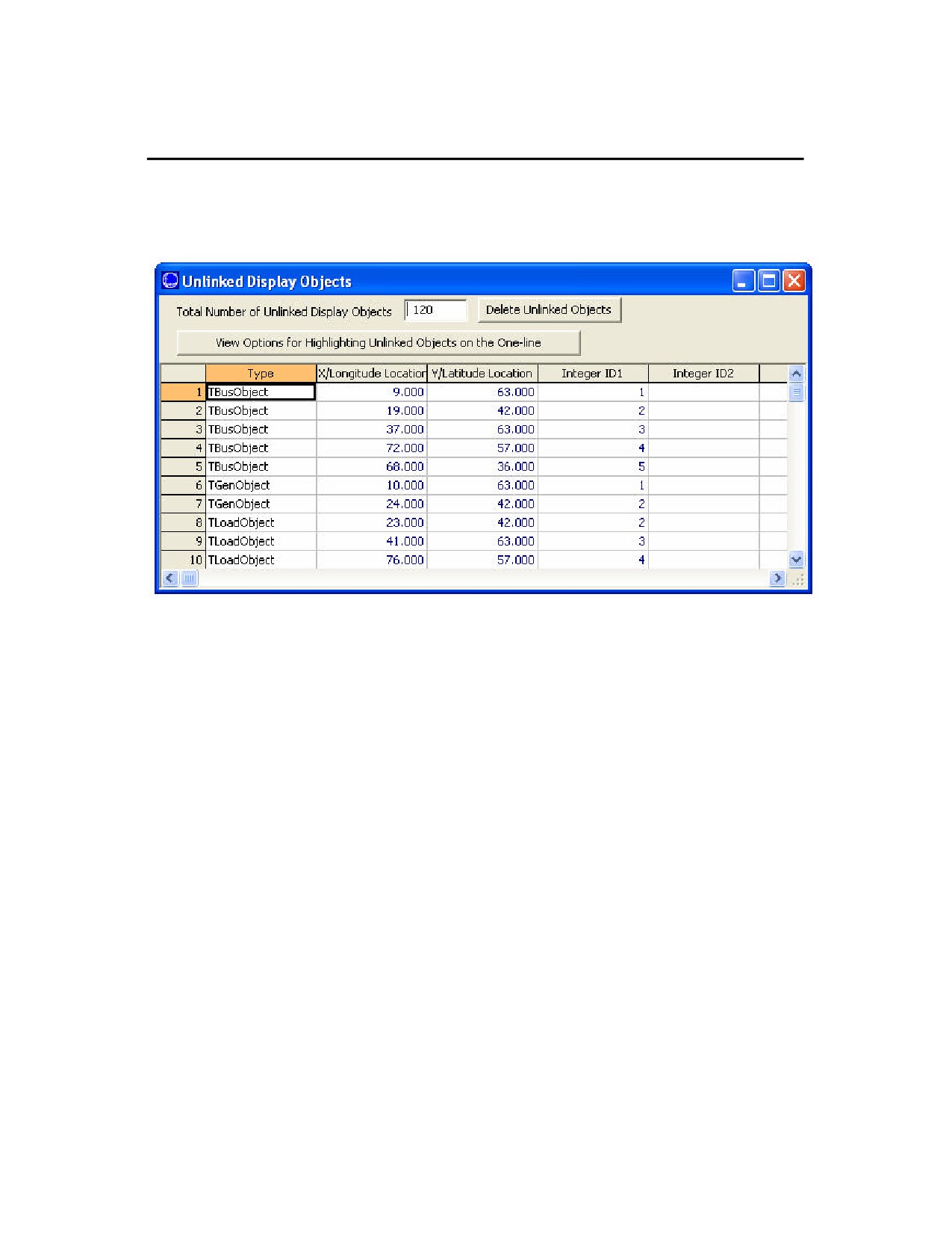
An unlinked object is a display object not linked to a record in the power system model (model object). The existence
of unlinked display objects on a oneline diagram can be misleading because they have zero flows and zero bus
voltages associated with them. See Object Relationships for more information.
Select Options > List Display Objects > Unlinked from the main menu in Edit Mode to identify unlinked objects.
Unlinked Display Objects Dialog
Total Number of Unlinked Display Objects
Indicates the total number of unlinked objects on the display. Ideally, this number should be zero. If nonzero, the
unlinked objects are identified in the table by type, screen location, and zoom range over which the object is visible.
Delete Unlinked Objects
Click on this button to permanently remove all unlinked objects from the display. Exercise this option carefully.
Generally, you will want to do this either when you have substantially modified a power flow case, such as by
creating an equivalent, or when you are using the oneline with a new power system case.
View Options for Highlighting Unlinked Objects on the Oneline
Click on this button will open the Grid/Highlight Unlinked Objects tab of the Oneline Display Options Dialog.
Type, X/Y Location
The remainder of the display shows the type, location, identification, layer, applicable zoom level, anchored
property, and font size for each unlinked object. This table is a type of Case Information Display and thus behaves
similarly to all other case information displays. Right-click on a record in this table to invoke the local menu. Select
Pan Oneline to Object to locate and select the unlinked object on the oneline diagram.
183

List All Display Objects
Select Options > List Display Objects > All from the main menu in Edit Mode to generate a list of all display objects
featured on the oneline diagram.
Oneline Objects Display
The Oneline Objects Dialog features a Case Information Display that identifies each display object by its type, X and
Y screen coordinates, what layer the object is contained in, whether or not it is subject to conditional zooming, if it is
anchored, and the font size (if applicable.) Since the table is a type of Case Information Display, it exhibits behavior
similar to that of all other case information displays.
Right-click on a record in the display to view the local menu. From the local menu, choose Delete to remove the
display object from the oneline. Choose Show Dialog to show the object’s corresponding information dialog. Finally,
choose Pan Oneline to Object to locate and select the corresponding display object on the oneline.
184