Amtrak. Graphic Signage Standards Manual (2010) - page 6

Electronic Signage
8.25
Train Information
and Visual
Messaging Screens
(Two Dedicated
Monitors)
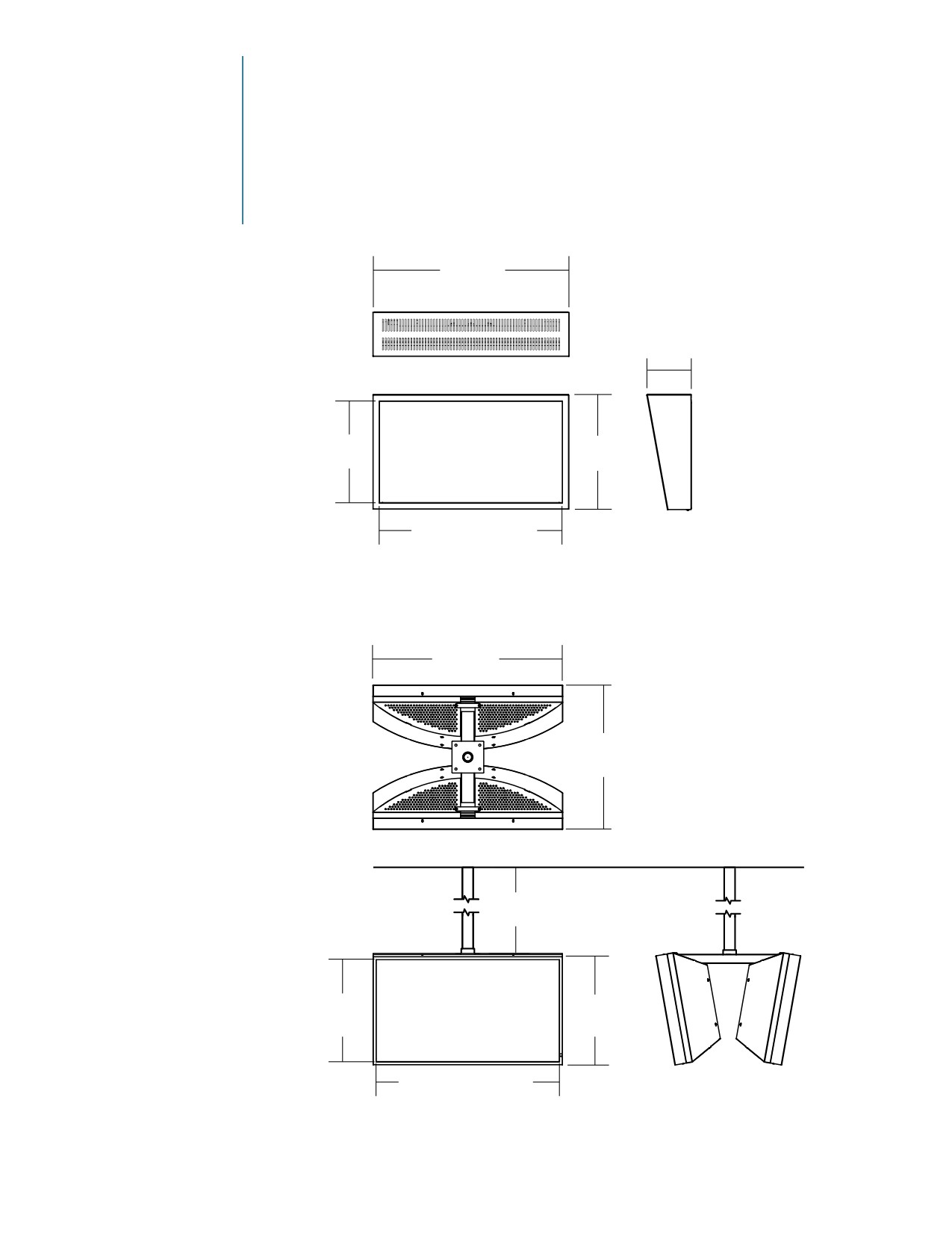
E7c and E7d Sign
Types
Sign Size and Layout
Display Technology
1'-2 1/2"
46” LCD flat screen dis-
(1'-1 3/4")
play monitor, NEC LCD
4620-2-AV, landscape
format.
3'-5 3/4" (3'-1/2")
40” LCD flat screen
display monitor, NEC LCD
4020-2-AV, landscape
Varies
format.
4" min.
12" max.
Screen Graphics
Proprietary Amtrak-
branded screen layouts
display all electronic
1'-10 1/2"
1'-11 7/8"
information in preset
(1'-8 7/8")
(1'-7 3/4")
text sizes for each moni-
tor size.
The Train Information
3'-4 1/2" (2'-11 1/4")
monitor lists up to 12
E7c Sign Type Ceiling Hung, Single-sided, Side-by-Side, 46” monitor
trains and can display
(40” monitor dimensions in parentheses)
one line of horizontally
scrolling free text. The
Visual Messaging monitor
displays several lines of
public announcement,
9 1/2"
emergency, or free text
which can be vertically
3'-4"
scrolled. Both screens
have a header which
displays current time and
2'-11 1/4"
a footer which displays
current day and date.
Static Graphics
Amtrak Logo: 1’-6” Wide
3'-11"
x 2” High (Sign Type E7d
only)
1'-7 3/4"
Comment
6'-6"
LCD screen graphics
are designed with ADA
guidelines in mind and
to reinforce the Amtrak
brand.
2'-3 1/2"
E7d Sign Type Freestanding, 40” monitor

Electronic Signage
8.26
Train Information
and Visual
Messaging Screens
(Two Dedicated
Monitors)
E7a and E7b Sign
Types
Design Intent
Drawing
Weight and power
1
requirements are listed
below each mounting
2
configuration.
Comments
• Power requirements
vary according to
E7a Sign Type Wall Mounted
number of monitors.
46” Monitors
40” Monitors
• Weight can change
Weight: 272 lbs.
Weight: 235 lbs.
based on prevailing
Power: 480 watts @ 120 volts
Power: 480 watts @ 120 volts
technology.
*For paint and color
specifications please refer
to page 2.10.
2
2
1
2
3
E7b Sign Type Ceiling Hung, Double-sided
46” Monitors
40” Monitors
Weight: 283 lbs.
Weight: 244 lbs.
Power: 480 watts @ 120 volts
Power: 480 watts @ 120 volts
General Specifications
1) Flatscreen LCD display monitor with tempered glass lens
2) Metal cabinet and support structures powdercoated to match Silver*
3) Reveals powdercoated to match Black*
■

Electronic Signage
8.27
Train Information
and Visual
Messaging Screens
(Two Dedicated
Monitors)
E7c and E7d Sign
Types
Design Intent
Drawing
Weight and power
requirements are listed
below each mounting
2
configuration.
Comments
• Power requirements
1
vary according to num-
ber of monitors.
2
• Weight can change
3
based on prevailing
technology.
E7c Sign Type Ceiling Hung, Single-sided, Side-by-Side
*For paint and color
46” Monitor (One Unit)
40” Monitor (One Unit)
specifications please refer
Weight: 148 lbs.
to page 2.10.
Power: 240 watts @ 120 volts
Power: 240 watts @ 120 volts
General Specifications
1
1) Flatscreen LCD
display monitor with
2
tempered glass lens
2) Metal cabinet and
support structures
powdercoated to
match Silver*
3) Reveals and base
powdercoated to
3
match Black*
4
4) Amtrak logo painted
AMT Blue*
3
E7d Sign Type Freestanding
40” Monitors
Weight: 570 lbs.
Power: 480 watts @ 120 volts

Electronic Signage
8.28
Train Information/
Visual Messaging
Screen (Single
Monitor)
E8 Sign Type
Sign Overview
This Sign Type utilizes
LCD flat screen electronic
display technology and
employs a single monitor
which displays two kinds
of information content
simultaneously on the
same screen. The top
Train Information sec-
tion provides a detailed
train information list
for multiple departures
E8a Sign Type Wall Mounted
E8b and E8c Sign Types Ceiling Hung
and arrivals mixed in
time order. The bottom
Visual Messaging section
provides visual display of
public announcements
and emergency messages
as well as free text mes-
sages.
E8 Sign Types are located
in interiors of stations
with light to moderate
passenger loads. Platform
and exterior use is dis-
couraged due to strict
weatherproofing and
mounting requirements.
Displays are operated by
Amtrak personnel from a
central controller located
in the communication
center.
E8d Sign Type Freestanding
■

Electronic Signage
8.29
Train Information/
Visual Messaging
Screen (Single
Monitor)
E8 Sign Type
Mounting Options
The following Mounting
Options provide guide-
lines for the placement of
E8 Sign Types. These signs
are to be placed in station
interiors in areas where
they can be easily viewed
by Amtrak customers.
Mounting
Configurations
E8a Wall mounted
(single-sided)
E8a Sign Type Wall Mounted
E8b Ceiling hung
(double-sided)
E8c Ceiling hung
(single-sided),
side-by-side
E8d Freestanding
(single-sided)
The E8 Sign Type
utilizes two monitor sizes,
depending on mounting
configuration, per the
chart below.
Mounting
Monitor Sizes
E8b Sign Type Ceiling Hung,
E8c Sign Type Ceiling Hung,
Double-sided
Single-sided
E8a
46”
40”
E8b
46”
40”
E8c
46”
40”
E8d
-
40”
Mounting requirements
and monitor sizes will
vary according to individ-
ual station needs includ-
ing viewing distances.
E8d Sign Type Freestanding
Electronic Signage
8.30
Train Information/
Visual Messaging
Screen (Single
Monitor)
E8a and E8b Sign
Types
Sign Size and Layout
Display Technology
3'-7 1/4"
46” LCD flat screen
(3'-3 1/2")
display monitor, NEC LCD
4620-2-AV, landscape
format.
9 1/2"
(9 1/2")
40” LCD flat screen
display monitor, NEC LCD
4020-2-AV, landscape
format.
Screen Graphics
1'-10 1/2"
2'-1 1/4"
(1'-7 3/4")
(1'-11 3/4")
Proprietary Amtrak-
branded screen layouts
display all electronic
information in preset
3'-4 1/2" (2'-11 1/4")
text sizes for each moni-
tor size.
E8a Sign Type Wall Mounted, 46” monitor
(40” monitor dimensions in parentheses)
Sign Type E8 utilizes a
single monitor to dis-
play Train and Visual
Messaging Information
3'-5 3/4"
simultaneously on the
(3'-1/2")
same screen. The top
Train Information section
lists up to 6 trains. The
bottom Visual Messaging
2'-7 3/4"
section displays several
(2'-7 3/4")
lines of public announce-
ment, emergency, or
free text which can be
vertically scrolled. Each
section has a header; cur-
rent time is displayed in
the top Train Information
header. The screen’s
Varies
footer displays current
day and date.
Comment
LCD screen graphics
are designed with ADA
1'-10 1/2"
1'-11 7/8"
(1'-7 3/4")
(1'-8 7/8")
guidelines in mind and
to reinforce the Amtrak
brand.
3'-4 1/2" (2'-11 1/4")
E8b Sign Type Ceiling Hung, Double-sided, 46” monitor
(40” monitor dimensions in parentheses)
■

Electronic Signage
8.31
Train Information/
Visual Messaging
Screen (Single
Monitor)
E8c and E8d Sign
Types
Sign Size and Layout
Display Technology
1'-2 1/2"
46” LCD flat screen
(1'-1 3/4")
display monitor, NEC LCD
4620-2-AV, landscape
format.
3'-5 3/4" (3'-1/2")
40” LCD flat screen
display monitor, NEC LCD
4020-2-AV, landscape
Varies
format.
Screen Graphics
Proprietary Amtrak-
branded screen layouts
display all electronic
1'-11 7/8"
1'-10 1/2"
information in preset
(1'-7 3/4")
(1'-8 7/8")
text sizes.
Sign Type E8 utilizes a
single monitor to dis-
3'-4 1/2" (2'-11 1/4")
play Train and Visual
E8c Sign Type Ceiling Hung, Single-sided, 46” monitor
Messaging Information
(40” monitor dimensions in parentheses)
simultaneously on the
same screen. The top
Train Information section
lists up to 6 trains. The
bottom Visual Messaging
9 1/2"
section displays several
3'-4"
lines of public announce-
ment, emergency, or
free text which can be
vertically scrolled. Each
section has a header; cur-
1'-7 3/4"
rent time is displayed in
the top Train Information
3'-11"
header. The screen’s
2'-11 1/4"
footer displays current
day and date.
Static Graphics
6'-6"
Amtrak Logo: 1’-6” Wide
x 2” High (Sign Type E8d
only)
Comment
LCD screen graphics
2'-3 1/2"
are designed with ADA
guidelines in mind and
to reinforce the Amtrak
brand.
E8d Sign Type Freestanding, 40” monitor

Electronic Signage
8.32
Train Information/
Visual Messaging
Screen (Single
Monitor)
E8a and E8b Sign
Types
Design Intent
Drawing
Weight and power
requirements are listed
1
below each mounting
configuration.
2
Comments
• Power requirements
E8a Sign Type Wall Mounted
vary according to
number of monitors.
46” Monitor
40” Monitor
• Weight can change
Weight: 136 lbs.
Weight: 113 lbs.
Power: 240 watts @ 120 volts
Power: 240 watts @ 120 volts
based on prevailing
technology.
*For paint and color
specifications please refer
to page 2.10.
2
2
1
2
3
E8b Sign Type Ceiling Hung, Double-sided
46” Monitors
40” Monitors
Weight: 283 lbs.
Weight: 244 lbs.
Power: 480 watts @ 120 volts
Power: 480 watts @ 120 volts
General Specifications
1) Flatscreen LCD display monitor with tempered glass lens
2) Metal cabinet and support structures powdercoated to match Silver*
3) Reveals powdercoated to match Black*
■

Electronic Signage
8.33
Train Information/
Visual Messaging
Screen (Single
Monitor)
E8c and E8d Sign
Types
Design Intent
Drawing
Weight and power
requirements are listed
below each mounting
2
configuration.
Comments
• Power requirements
1
vary according to
number of monitors.
2
• Weight can change
3
based on prevailing
technology.
E8c Sign Type Ceiling Hung, Single-sided
*For paint and color
46” Monitor
40” Monitor
specifications please refer
Weight: 148 lbs.
Weight: 122 lbs.
to page 2.10.
Power: 240 watts @ 120 volts
Power: 240 watts @ 120 volts
General Specifications
1) Flatscreen LCD
1
display monitor with
2
tempered glass lens
2) Metal cabinet and
support structures
powdercoated to
match Silver*
3) Reveals and base
3
powdercoated to
match Black*
4
4) Amtrak logo painted
AMT Blue*
3
E8d Sign Type Freestanding
40” Monitor
Weight: 506 lbs.
Power: 240 watts @ 120 volts
Electronic Signage
8.34
Master Clock System
E9 Sign Type
Sign Overview
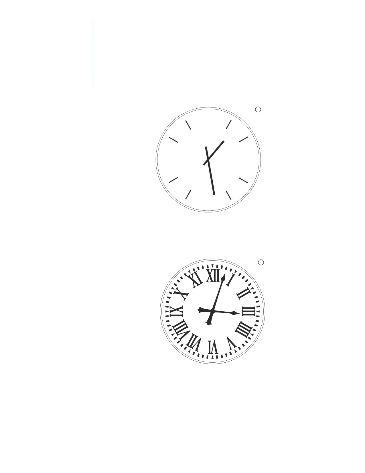
The master clock system
is a separate unit linked
1
by a central controller
to display the same time
12
on all clocks throughout
a station. It provides a
common time reference
for Amtrak employees,
customers and the gen-
9
3
eral public.
To provide some flexibil-
ity and accommodate the
needs of all stations, two
clock faces have been
selected for the Amtrak
6
Graphic Signage System.
E9 Sign Type
1) General Purpose
L Face
(Contemporary)
White dial, black
Frutiger 55 Roman
numerals at the 12, 3,
2
6 and 9 o’clock posi-
tion and bars at the
other hour positions.
LS Hands
(Contemporary)
Basic hands recom-
mended for use in
most stations.
2) Historic Stations
A Face (Historic)
White dial, black
Roman numerals at
all hour positions.
AS Hands
E9 Sign Type
(Historic) Old-style
recommended for use
in stations considered
historic.
■

Electronic Signage
8.35
Master Clock System
E9 Sign Type
Typical Elevations
and Specifications
The illustration on this
page gives general size
and layout recommenda-
tions. The project architect/
designer may interpret
materials and design
based on the Graphic
Signage Standards Manual
1
2
3
and the individual station
E9 Sign Type
E9 Sign Type
E9 Sign Type
environment.
Double Face
Surface
Semi-flush
1) Style 53918
Double Face Design
2'-0"
18” diameter
Clear Acrylic Crystal
White Dial. Specify
if sidewall, ceiling or
pendant mounting.
2) Style 52918
Surface Design
18” diameter Clear
4
Acrylic Crystal White
Dial
3) Style 50918
Semi-flush Design
18” diameter Clear
Acrylic Crystal White
Dial
4) Custom Clock Tower
Custom Clock Towers
are used as landmarks
within stations as a
gathering or meeting
place for Amtrak
customers.
Weight
Clock is approx. 18 lbs.
E9 Sign Type
Clock Tower
Housing
Aluminum case with satin
aluminum finish or matte
black.
Typical Sign
9.1
Location Plans
Message Hierarchy
To ensure functionality of the Amtrak Graphic Signage
Amtrak’s approach to
System, information must be presented in such a way
providing information
as to allow for smooth traffic flow throughout the
requires a systematic
station facilities.
display of different
types of messages as
The placement of all signs must reflect the needs of
passengers’ needs vary
the user. By presenting digestible amounts of messages
throughout the differ-
far enough in advance of a decision point, passengers
ent environments in
can prepare for what is ahead. The progression usually
the station.
starts with broad general information and moves, as
one approaches a decision point, towards more specific
Directional signing is
and detailed information. Within Amtrak’s Signage
of great importance.
System, messages should progress from general (Trains)
When used correctly,
to specific (Gate, then Track Number and Boarding
proper directional
Location).
signing will assist
in the rapid move-
The typical sequences of concern entraining are:
ment of vehicles, visi-
1. Approach/Parking/Passenger Drop-off
tors, and customers.
2. Tickets
Success or failure of
3. Baggage Check-in
a station’s design and
4. Restrooms
its signing will be
5. Trains
measured by the ease,
speed, comfort and
The typical sequences of concern detraining are:
access to and from the
1. Restrooms
various destinations
2. Baggage Claim
within the station.
3. Buses/Taxis/Parking
Comment
4. Telephones
The location plans in this
5. Exit
chapter are diagrammatic
Exterior Site Conditions
and represent general
arrangements for vari-
Passengers approaching a station will require immedi-
ous platform and station
ate information directing them to Parking, Passenger
building categories.
Drop-off/Pick-up and the station entrance.
Configurations of actual
Interior Conditions
stations will vary and
signs should be located
Once at the station entrance, these same passengers
and messaged according
will require information leading to the interior of the
to each site’s layout.
station where they will then find information regarding
public and passenger services. Once the Tickets/Baggage
Check-in process is completed, the passenger requires
guidance to the Waiting Area, Gate/Track locations as
well as additional reinforcement of train information.
Platform Conditions
Once passengers have purchased tickets and checked in
their baggage, they will require guidance to Track or
Gate locations and finally Boarding Locations for proper
boarding and seating.
Typical Sign
Location Plans
9.2
Historic Buildings
A historic building is
Any structure or collection of structures deemed
one that has received
important to the history, architecture or culture of an
an official designation
area is considered a historic landmark. The Secretary
from local, state, or
of the Interior has established standards for the
federal governmental
historic preservation of these properties. Guidelines
entities.
for rehabilitating historic buildings have been estab-
lished to ensure the preservation of qualities for
which each property was listed.
Accessibility to historic buildings is required by the
Americans with Disabilities Act as well as other state
or local laws. Federal regulations have been devel-
oped to provide guidance on how to meet both
accessibility and historic preservation requirements.
Compliance with these requirements, in addition to
local and state regulations is required when incorpo-
rating the Amtrak Graphic Signage Standards.
For additional information refer to The Secretary
of the Interior’s Standards for Rehabilitation with
Illustrated Guidelines for Rehabilitating Historic
Buildings (updated 1995), available at www.nps.gov/
history/hps/tps/tax/rhb.
Contact Amtrak Signage Brand Management at
SignageBrandManagement@amtrak.com regarding
implementation of Amtrak Graphic Signage Standards
at designated historical facilities.
■
Typical Sign
9.3
Location Plans
Stub-end Platforms
Recommended Sign
Location Layout
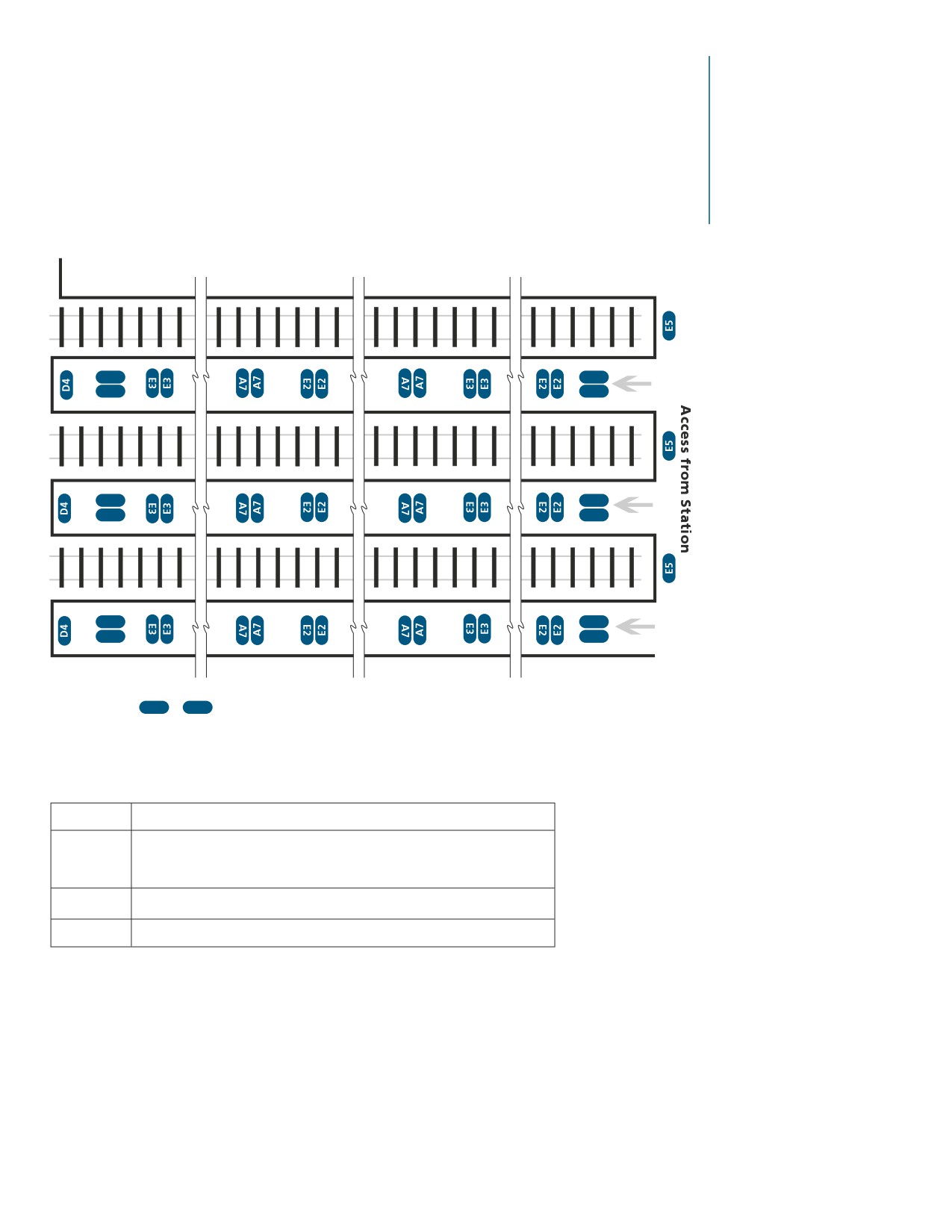
Stub-end platforms are
approached from one
end only. This diagram
represents a typical sign
location plan for a
multiple platform site.
It may be accessible at
A1a
A1a
grade or by raised
platforms.
Stations at the end of
a line do not require
signs with information
regarding train’s origin/
A1a
A1a
destination. The city and
state name alone will
suffice.
Comments
• Columns, stairs, eleva-
tors and other struc-
A1a
A1a
tures along platform
centerlines can obstruct
sightlines of signs
located perpendicular
A11
& A12
Location in platform area to be determined for each station
to the platform. In such
cases, signs should be
placed along both sides
Recommended Sign Placement
of platform for obstruc-
Signs should be placed along active platform at intervals indicated below.
tion-free viewing.
A1a
170'-0" apart (two car lengths starting from engineer's stop).
• Ultraviolet radia-
tion tends to bleach
A7
85'- 0" apart (starting at head end); 87'-6" for Acela Express equipment.
the color from signs
Spacing may require modification with the procurement of additional
exposed to the sun.
equipment for other HSR networks.
E2
85'-0" apart (stagger with A1a and A7 signs to avoid crowding).
Key to Sign Layout
E3
170'-0" apart (stagger with A1a and A7 signs to avoid crowding).
A1a Branded City Identifier
A7 Boarding Location
Marker and Track
Identifier (Suspended)
A11 Station Information
Display Case
A12 ADA City Identifier
D4
Restrictive Sign
E2
Next Train Information
E3 Visual Messaging System
E5 Bumper Block Train
Information Board
Typical Sign
Location Plans
9.4
Center Access
Platforms
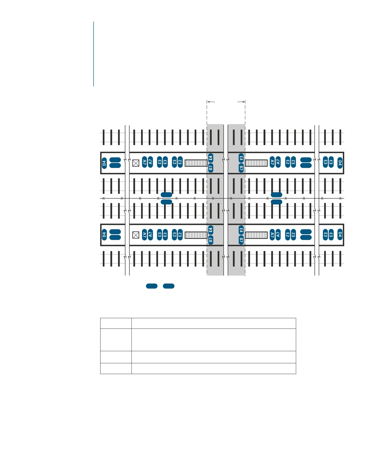
Recommended Sign
Location Layout
This diagram represents a
Access not
at Grade
typical sign location plan
(shaded area indicates track
overpass
for a multiple platform
or underpass from station)
site not accessible at
grade.
Stations at the end of
a line do not require
signs with information
regarding train’s origin/
A1a
A1a
destination. The city and
elevator
state name alone will
suffice.
Comments
D4
D4
• Columns, stairs, eleva-
tors and other struc-
tures along platform
centerlines can obstruct
sightlines of signs
A1a
A1a
located perpendicular
elevator
to the platform. In such
cases, signs should be
placed along both sides
of platform for obstruc-
tion-free viewing.
• Ultraviolet radia-
A11
& A12
Location in platform area to be determined for each station
tion tends to bleach
the color from signs
Recommended Sign Placement
exposed to the sun.
Signs should be placed along active platform at intervals indicated below.
Key to Sign Layout
A1a or A2a
170'-0" apart (two car lengths starting from engineer's stop).
A1a Branded City Identifier
A7
85'- 0" apart (starting at head end); 87'-6" for Acela Express equipment.
OR
Spacing may require modification with the procurement of additional
A2a Branded City Identifier
equipment for other HSR networks.
with Direction Bar
E2
85'-0" apart (stagger with A1a/A2a and A7 signs to avoid crowding).
A7 Boarding Location
Marker and Track
E3
170'-0" apart (stagger with A1a/A2a and A7 signs to avoid crowding).
Identifier (Suspended)
A11 Station Information
Display Case
A12 ADA City Identifier
B7 Gate Identification
D4
Restrictive Sign
E2
Next Train Information
E3 Visual Messaging System
E4
Gate Board
■

Typical Sign
9.5
Location Plans
Multiple Through-
track Platforms
Recommended Sign
Location Layout
Station
The diagram shown
or Shelter
below illustrates a typi-
Track Crossing
cal sign location plan for
Access at Grade
a multiple platform site
with through-track
traffic.
A2a
A2a
Access is at grade.
Contact Amtrak for
specific signage require-
ments for pedestrian
crossings on active tracks.
Comments
A2a
A2a
• Columns, stairs, eleva-
tors and other struc-
tures along platform
centerlines can obstruct
sightlines of signs
located perpendicular
to the platform. In such
A11 & A12 Location in platform area to be determined for each station
cases, signs should be
placed along both sides
of platform for obstruc-
Recommended Sign Placement
tion-free viewing.
Signs should be placed along active platform at intervals indicated below.
• Ultraviolet radia-
A2a
170'-0" apart (two car lengths starting from engineer's stop).
tion tends to bleach
the color from signs
A6
85'- 0" apart (starting at head end); 87'-6" for Acela Express equipment.
exposed to the sun.
Spacing may require modification with the procurement of additional
equipment for other HSR networks.
Key to Sign Layout
E2
85'-0" apart (stagger with A2a and A6 signs to avoid crowding).
A2a Branded City Identifier
E3
170'-0" apart (stagger with A2a and A6 signs to avoid crowding).
with Direction Bar
A6 Boarding Location
Marker and Track
Identifier with Arrow
A10 Passenger Information
and Timetable Display
A11 Station Information
Display Case
A12 ADA City Identifier
D4
Restrictive Sign
E2
Next Train Information
E3
Visual Messaging System

Typical Sign
Location Plans
9.6
Single Through-track
Platform
Recommended Sign
Location Layout
The diagram shown
Station or Shelter
below illustrates a typical
sign location plan for a
single platform site with
A1a
A1a
through-track traffic.
Access is at grade.
Contact Amtrak for
specific signage require-
ments for pedestrian
crossings on active tracks.
Comment
A11 & A12 Location in platform area to be determined for each station
Ultraviolet radiation
tends to bleach the color
from signs exposed to
Recommended Sign Placement
Signs should be placed along active platform at intervals indicated below.
the sun.
A1a/A2a
170'-0" apart (two car lengths starting from engineer's stop).
Key to Platform Layout
A4
85'- 0" apart (starting at head end); 87'-6" for Acela Express equipment.
A1a Branded City Identifier
Spacing may require modification with the procurement of additional
OR
equipment for other HSR networks.
A2a Branded City Identifier
with Direction Bar
E2
85'-0" apart (stagger with A1a/A2a and A4 signs to avoid crowding).
A4 Boarding Location
E3
170'-0" apart (stagger with A1a/A2a and A4 signs to avoid crowding).
Marker
A11 Station Information
Display Case
A12 ADA City Identifier
D4
Restrictive Sign
E2
Next Train Information
E3 Visual Messaging System
■

Typical Sign
9.7
Location Plans
Large Stations
Recommended Sign
Location Layout
Key to Sign Layout
B20
Mechanical Room
C9 - Site Identification
The illustrated station
C12
Monument (Sign Type,
is shown for signage
B1
To Trains
B24
Branded Station Hours
size and illumination to
purposes only. Additional
B2
Trains/Restrooms
B25 Travelscape at Ticket
be determined)*
Counter
requirements that may
B2
Taxis/Exit
C20
ADA Station Entrance
impact the station design
B26
Brandmark
Identifier
B7 Tickets & Baggage
and layout can be found
at Ticket Counter
Check-in
D2
Smoke-free Facility
in the Amtrak Station
B27
Amtrak Welcomes You
B7
Passenger Services
E4
Gate Board
Design Guidelines. The
to “City Name”
B15 Baggage Claim
E6 Train Directory Board
Station is designed to
B27 Station Identification
B15
Restrooms
E7
Train Information
efficiently handle moder-
C1
Reserved Parking*
and Visual Messaging
ate to heavy passenger
B15
Telephones
C2
Amtrak Thruway
Screens
loads of 150-300 passen-
B15
TDD
Bus
gers per peak hour.
B17
Men
C2 Passenger Drop-off
* Signage to comply
and Pick-up
Comment
B17
Women
with local codes.
C2
Taxis
Ultraviolet radiation
B18
Men
C4 Parking/Amtrak
tends to bleach the color
B18
Women
Thruway Bus
from signs exposed to
the sun.
Platform (refer to typical platform plans)
E4
To be located at each gate to platform(s)
Waiting Area
Private
B1
Offices
Baggage
Room
B25
B26
E6
Station Interior
B15
B7
B2
B20 B18 B17
B17 B18
B24
B24
B27
C20
D2
Sidewalk
One Way
C4

Typical Sign
Location Plans
9.8
Medium Stations
Recommended Sign
Location Layout
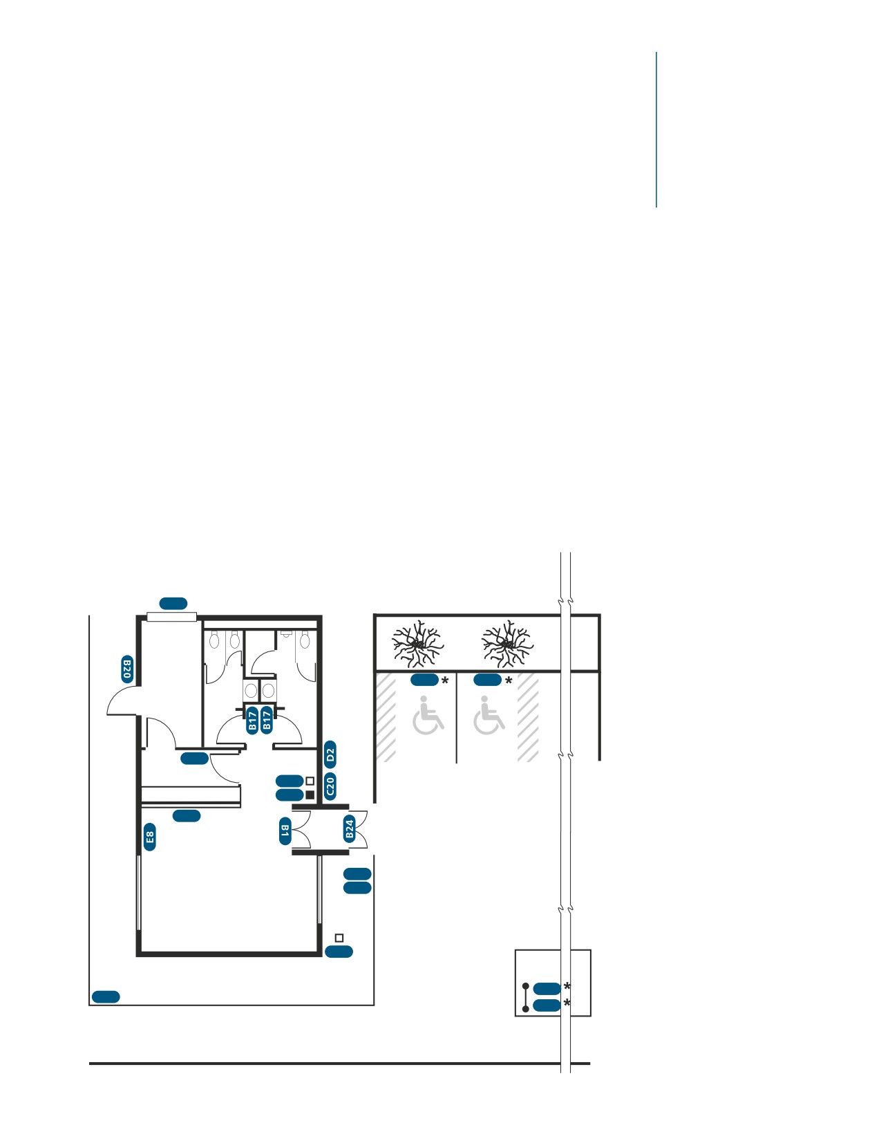
The illustrated station
Key to Sign Layout
B21
Authorized
C4
Parking/Amtrak
Personnel
Thruway Bus
is shown for signage
B2
Trains/Restrooms
location purposes only.
B24
Branded Station Hours
C9 -
Site Identification
B2
Taxis/Exit
C12
Monument (Sign Type,
Additional requirements
B25
Travelscape at Ticket
B7
Tickets & Baggage
size and illumination to
that may impact station
Counter
Check-in
be determined)*
design and layout can
B26
Brandmark at Ticket
B7 Baggage Claim
Counter
C20
ADA Station Entrance
be found in the Amtrak
Identifier
Station Manual. Station
B15
Restrooms
B27
Amtrak Welcomes You
to “City Name”
D2
Smoke-free Facility
is designed to efficiently
B15
Telephones
B27
To Trains
E4
Gate Board
handle moderate passen-
B15
TDD
ger loads of 50-175
C1
Reserved Parking*
E8
Train Information/
B17
Men
Visual Messaging
passengers per peak
B17
Women
C2
Amtrak Thruway Bus
Screen
hour.
B18
Men
C2
Passenger Drop-off
Comment
and Pick-up
B18
Women
*
Signage to comply
C2
Taxis
Ultraviolet radiation
with local codes.
tends to bleach the color
from signs exposed to
the sun.
Platform (refer to typical platform plans)
E4
To be located at each gate to platform(s)
B27
Baggage Room
i.03
Ticket
Office
Waiting Area
E8
B15
B2
B15
C20
D2
B24 B24
Sidewalk
C9 or
C10 or
One Way
C11 or
C12
C4
■
Typical Sign
9.9
Location Plans
Small Stations
Recommended Sign
Location Layout
Key to Sign Layout
C2 Amtrak
The illustrated station
Thruway Bus
is shown for signage
B1
Exit
C2 Passenger Drop-off
location purposes only.
B7 Tickets and
and Pick-up
Additional requirements
Baggage Check-in
C7 - Site Identification Sign
that may impact station
B7
Baggage Claim
C8
(Post and Panel)
design and layout can
B14
Telephones
C20
ADA Station Entrance
be found in the Amtrak
B15
TDD
Identifier
Station Manual. Station
B17
Men
D2
Smoke-free Facility
is designed to efficiently
B17
Women
E8
Train Information/
handle light passenger
Visual Messaging
loads of 25-75 passengers
B20
Private
Screen
per peak hour.
B24
Branded Station Hours
B26
Brandmark at Ticket
Comment
* Signage to comply
Counter
Ultraviolet radiation
with local codes.
C1
Reserved Parking*
tends to bleach the color
from signs exposed to
the sun.
Platform (refer to typical platform plans)
Baggage
Room
C1
C1
B26
B14
B15
B7
C2
Waiting Area
B14
C7
C2
Sidewalk
or
C8

Typical Sign
Location Plans
9.10
Shelters
Recommended Sign
Location Layout
The illustrated station
A11 & A12 Location in platform area to be determined for each station
is shown for signage
Platform (refer to typical platform plans)
location purposes only.
Additional requirements
that may impact station
design and layout can
C1
C1
be found in the Amtrak
Station Manual. Station
Shelter Area
is designed to efficiently
handle minimal passen-
Exterior
ger loads of 25 passen-
C7
gers per peak hour.
or
C8
Comment
Ultraviolet radiation
tends to bleach the color
from signs exposed to
the sun.
Key to Sign Layout
A11 Station Information
Display Case
A12 ADA City Identifier
B14
Telephones
C1
Reserved Parking
C7 - Site Identification Sign
C8
(Post and Panel)
* Signage to comply
with local codes.
■
Recommended
10.1
Maintenance of
Signs
Maintenance and
Parts Replacement
• Screws and bolts must be tightened periodically.
To ensure that the
Check for missing screws, nuts and bolts. These
Amtrak Graphic
tend to get lost during maintenance procedures.
Signage System
continues to effec-
• Damaged bolts and screws must be replaced imme-
tively communicate a
diately. Damaged signs that may present a hazard
positive brand image,
should be removed or replaced immediately (i.e.,
the following guide-
rusting that threatens the structural integrity of
lines for repair and
a sign unit, deterioration of electrical wiring or
replacement must be
broken sign faces).
followed closely.
• Check sign boxes and anchor bolts for cracks.
Suspended signs are in constant motion, putting
stress on bolts and stop nuts.
• For the removal and installation of any sign,
contact a sign installation professional or
SignageBrandManagement@amtrak.com.
• For additional signs required at a station site,
contact a sign installation professional or
SignageBrandManagement@amtrak.com. Also see
Chapter 12 for Sign Ordering Forms.
• All signs must be checked after hurricanes, earth-
quakes and wind loads exceeding 60 mph.
• Remove graffiti and replace vandalized sign
components, such as broken glass, promptly
to prevent further vandalism. Contact
SignageBrandManagement@amtrak.com if infor-
mation is needed on graffiti removal or replace-
ment of vandalized sign parts.
Recommended
Maintenance of
10.2
Signs
Cleaning
Amtrak Signs should
Painted Aluminum, Anodized Aluminum
be properly and peri-
and Fiberglass Signs
odically cleaned to
These surfaces are cleaned most easily using mild
maintain their clarity
soaps, detergents or solvents applied to the surface
and effectiveness.
with a soft cloth or sponge. For more stubborn stains,
The following guide-
solvents such as rubbing alcohol, mineral spirits or
lines must be followed
Bestine may be used.
when cleaning signs.
Do not use scouring pads or cleaners containing
abrasives, which will scratch surfaces. If heavy duty
cleaning is required, professional assistance should be
requested.
Acrylic, PVC Letters and Vinyl Signs
Cleaning should be done with a soft cloth and
window cleaner. Do not use cloths containing grit,
abrasive particles or scouring compounds to clean
plastic as they will scratch and damage the sign
surface.
Granite and Concrete
These surfaces should be cleaned with a mild soap and
a soft bristled brush for most cases. In the event that
the surface has an embedded stain, a power sprayer
and a mild soap may be utilized. However, this should
be done only by an experienced professional.
Brass Letters
Some older stations may have brass lettering that was
part of the original station design. Extreme care must
be taken when cleaning any brass surface. Cleaning
should only be done utilizing a soft cotton cloth. The
use of soaps, detergents or solvents is not recom-
mended as they may cause scratches in the finish,
requiring a new clear coat finish to deter the letters
from pitting.
Electronic and Internally Illuminated Signage
Maintenance contracts with the Electronic Signage
Supplier are strongly recommended. Frequency of
cleaning varies with local conditions. Specific methods
of cleaning must be coordinated with the supplier.
Time clocks and energy management systems must
be checked as they may be operating 24 hours a day,
shortening lamp life and increasing your energy costs.
Supply voltage and grounding must be checked.
Voltage drops can affect the life of lamps and ballasts.
■
Recommended
10.3
Maintenance of
Signs
Why Coating
Systems Fail
Many factors influence the life and performance
of coating systems. Recognizing the exposure condi-
tions and specifying the proper coatings is the first
step in obtaining satisfactory coating performance.
Specifying adequate preparation and coatings, com-
bined with on-the-job inspection during preparation
and application, serve to assure the best possible coat-
ing performance.
Broadly defined problems which cause deterioration
fall into one or more of the following categories. The
station site should be examined to assess the presence
of these either separately or in combination.
1.) Heat
Heat can cause coatings to discolor, blister and
burn off.
2.) Moisture
This problem may include exposure to steam,
humidity, condensation or actual immersion in
water. Coatings shall repel moisture to protect
the surface.
3.) Impact
Concrete will wear and can crack and chip. This
material may require special coatings.
4.) Abrasion
All surfaces in high traffic areas are subject to
damage from abrasion.
5.) Atmospheric Corrosion
Constant exposure to the elements—rain, cold,
heat, temperature changes and the ultraviolet rays
of the sun—may wear away a protective coating.
For a coating to work effectively, it must be tough
enough to resist the elements and be flexible
enough to expand and contract with the surface to
which it is applied.
6.) Chemical Corrosion
Acids and alkalies will attack and destroy ordinary
protective coatings.
Sign Fabrication
11.1
and Installation
The Amtrak
Paint System
Sign Paint System Description
Amtrak Sign Paint
In general, the paint system used for Amtrak signs is a
System
low VOC, ultraviolet inhibited aliphatic acrylic polyure-
MPC - Matthews Paint
thane applied over pretreatment coatings and primers,
Company
as appropriate for each sign substrate material. All signs
MAP - Matthews Acrylic
are clear coated with low VOC satin clear coat unless
Polyurethane
indicated otherwise on design intent drawings.
MAP VOC-compliant
Matthews Paint Company (MPC) manufactures the paint
paint and clear coat des-
system used for most Amtrak sign applications, formu-
ignations, and standard
lated around Matthews Acrylic Polyurethane (MAP) as
AMT colors, are included
the pigmented topcoat. MAP VOC-compliant paint and
on page 2.10.
clear coat designations, and standard AMT colors, are
included on page 2.10.
Comment
This paint system is for
Volatile Organic Compound (VOC) Requirements
application over new,
To promote a greener environment, the Amtrak paint
never-painted substrates.
system specifies paint coatings compliant with govern-
If painting over existing
ing VOC-emission requirements. VOC-compliant coat-
painted signs, this sys-
ings, although more expensive, are required to have
tem will blister and peel.
equal performance properties to conventional coatings.
Therefore, another paint
Cleaning, Pretreating and Painting
system should be selected
Clean, pretreat, paint and clear coat according to proce-
where painting over
dures recommended for each substrate in the VOC MAP
existing paint is based
Substrate Application Guide, available online at
upon a history of success-
ful use. In general, paint-
ing over existing signs is
Touch-up after Installation
discouraged.
Perform after-installation touch-up with VOC-compli-
ant coatings in accordance with paint manufacturer’s
recommendations.
Touch-up of Damage: Signs damaged before shipment
are unacceptable. Only minor on-site damage may be
touched-up, subject to Amtrak’s acceptance.
Painting on Plaster, Gypsum Board and Cork
Do not use Matthews Acrylic Polyurethane (MAP) or any
other polyurethane on these surfaces. Another type of
paint system should be selected based upon history of
successful use.
Sign Fabrication
and Installation
11.2
Graphics Application
Permanent Graphics
Permanent sign graphics are to be applied by frisket
(mask) painting or by silkcreening. Both processes
provide good durability and reproduction quality, and
can be substituted for each other. Silkscreen inks must
match Amtrak paint colors specified on page 2.10. All
painted and silkscreened graphics must be applied
before signs are clear coated.
Cut Vinyl Graphics
Cut Vinyl Graphics are signs only where specified, as
the primary or alternate finish in the design intent
drawing for each Amtrak Sign Type.
Follow vinyl manufacturer’s instructions for cleaning
and preparation of specific surfaces to which the vinyl
is to be applied, and for application of the vinyl.
■
Sign Fabrication
11.3
and Installation
Sign Construction
Drawings
Sign Construction Drawings
Drawings outlining fabrication specifications of Sign
Types contained in this manual are currently being
updated and will be available to design professionals
working on Amtrak facilities. These drawings, which
are not be used in lieu of obtaining shop drawings
from selected sign fabricators, can be obtained by
contacting SignageBrandManagement@amtrak.com.
Amtrak personnel seeking to obtain signs for their
facilities should order signs using the process outlined
in Chapter 12.
Sign
12.1
Ordering Forms
The Ordering Process
This chapter provides the necessary information for
Sign Ordering is key
Amtrak personnel to order Amtrak signs.
to the implementation
of the Amtrak Graphic
Signs for the Amtrak Graphics Signage System have
Signage System.
been categorized into five groups.
Adherence to the
“A” Sign Types represent Platform Signs (Chapter 4.0)
three-step procedure
“B” Sign Types represent Interior Signs (Chapter 5.0)
mentioned in this
“C” Sign Types represent Exterior Signs (Chapter 6.0)
chapter will ensure
“D” Sign Types represent Regulatory Signs (Chapter 7.0)
the proper processing
“E” Sign Types represent Electronic Signs (Chapter 8.0)
of orders for new or
To ensure that Amtrak signage is manufactured to high
replacement signs.
quality standards, Amtrak personnel must order signs
through Amtrak Signage Brand Management following
the three-step procedure in this chapter. It is important
to note that not all local companies can produce the
signage to the listed specifications and that any locally-
obtained signage that does not comply with Amtrak
specifications will be removed.
Design professionals seeking competitive bids for sta-
tion signage should verify that any company submit-
ting a price has the ability and the experience to pro-
duce high quality architectural signage that conforms
to the specifications. Design professionals must require
selected fabricator to submit complete shop drawings
and other pertinent submittals. Should design profes-
sionals have questions or require assistance in locating
sign fabricators, contact SignageBrandManagement@
amtrak.com or Amtrak Procurement.
Sign
Ordering Forms
12.2
Master List
of Sign Types
Sign Type
Sign Name
Page #
Additional ordering
Static Platform Signs
information can be
A1a
Branded City Identifier
pg 4.2
found on pages 12.6
A1
City Identifier
pg 4.6
and 12.7.
A2a
Branded City Identifier with Direction Bar
pg 4.2
Signs for the Amtrak
A2
City Identifier with Direction Bar
pg 4.6
Graphic Signage
A3
Track Identifier
pg 4.10
System have been
A4
Boarding Location Marker
pg 4.10
listed by Sign Type and
A5
Boarding Location Marker and Track Identifier
pg 4.10
Sign Name.
A6
Boarding Location Marker and
Track Identifier with Arrow
pg 4.10
*Indicates internally
A7
Boarding Location Marker
illuminated signs
and Track Identifier with Arrow (Suspended)
pg 4.10
A8
Track Identifier (at Bumper Block)
pg 4.10
A9
Directional Stacked
pg 4.16
A10
Directional Single Line
pg 4.16
A11
Station Information Display Case
pg 4.20
A12
ADA City Identifier
pg 4.24
Static Interior Signs
B1
Overhead Directional One Message
pg 5.2
B2
Overhead Directional Two Messages
pg 5.2
B3
Overhead Directional Three Messages
pg 5.2
B4
Overhead Directional One Message
with Preview Bar
pg 5.6
B5
Overhead Directional Two Messages
with Preview Bar
pg 5.6
B6
Overhead Directional Three Messages
with Preview Bar
pg 5.6
B7
Sign Band
pg 5.10
B8
Wall Directional One Message
pg 5.14
B9
Wall Directional Two Messages
pg 5.14
B10
Wall Directional Three Messages
pg 5.14
B11
Wall Directional One Message
with Preview Bar
pg 5.18
B12
Wall Directional Two Messages
with Preview Bar
pg 5.18
B13
Wall Directional Three Messages
with Preview Bar
pg 5.18
B14
Service Identifier with Symbol Only
pg 5.22
B15
Service Identifier with Symbol and Message
pg 5.22
B16
Service Identifier with Symbol and Extended
Message Panel
pg 5.22
■
Sign
12.3
Ordering Forms
Master List of
Sign Types
Sign Type
Sign Name
Page #
(continued)
B17
Restroom Wall Identifier
pg 5.26
*Indicates internally
B18
Restroom Door Identifier
pg 5.26
illuminated signs
B19
Permanent Room Number Identifier
pg 5.30
B20
Permanent Room Identifier
for Short Messages
pg 5.30
B21
Permanent Room Identifier
for Long Messages
pg 5.30
B22a
Freestanding 11x17 Custom Message Inserts
and Sign Housing
pg 5.34
B22b
Freestanding 22x28 Custom Message Inserts
and Sign Housing
pg 5.34
B23a
Wall mounted 11x17 Custom Message Inserts
and Sign Housing
pg 5.39
B23b
Wall mounted 22x28 Custom Message Inserts
and Sign Housing
pg 5.39
B23c
Wall mounted 24x36 Custom Message Inserts
and Sign Housing
pg 5.39
B24
Station Hours Lettering
pg 5.45
B25
Travelscape
pg 5.47
B26
Brandmark
pg 5.48
B27
Individually-cut Letters
pg 5.49
B28
Interior Cut Vinyl Applied Letters
pg 5.51
B29
Changeable Message Insert Sign
pg 5.54
B30
Brand Identification Fin
pg 5.57
Static Exterior Signs
C1
Curb Identifier
pg 6.2
C2
Curb Identifier with Additional Message Field
pg 6.2
C3
Vehicular Directional One Message
pg 6.6
C4
Vehicular Directional Two Messages
pg 6.6
C5
Vehicular Directional Three Messages
pg 6.6
C6
Parking Directional One Message (General)
pg 6.6
C7
Freestanding Post & Panel Site Identification Sign
Vertical Orientation
pg 6.12
C8
Freestanding Post & Panel Site Identification Sign
Horizontal Orientation
pg 6.12
C9*
Freestanding Vertical Site Identification Pylon,
Internally Illuminated
pg. 6.15
C10
Freestanding Vertical Site Identification Pylon,
Externally Illuminated
pg. 6.15
C11*
Freestanding Horizontal Site Identification
Monuments, Internally Illuminated
pg. 6.18
C12
Freestanding Vertical Site Identification
Sign
Ordering Forms
12.4
Master List
of Sign Types
(continued)
Sign Type
Sign Name
Page #
*Indicates internally
Monument, Externally Illuminated
pg. 6.18
illuminated signs
C13*
Monument Station Site Identification Sign
pg. 6.21
C14
Brand Identification Fin
pg. 6.22
C15
Trailblazer Kit #1
pg. 6.23
C16
Trailblazer Kit #2
pg. 6.23
C17
Trailblazer Kit #3
pg. 6.24
C18
Trailblazer Kit #4
pg. 6.24
C19
Trailblazer Kit #5
pg. 6.24
C20
ADA Station Entrance Identifier
pg. 6.27
Static Regulatory Signs
D1
Regulatory Sign Symbol Only
pg 7.2
D2
Regulatory Sign with Symbol and Message
pg 7.2
D3
Safety Signs
pg 7.6
D4
Platform End Restrictive Sign
pg 7.10
D5
Safety Tips Sign
pg 7.14
D6
Security Warning Sign
pg 7.18
Electronic Signs
E1
Next Agent Available System
pg 8.2
E2
Next Train Information (LED)
pg 8.6
E3
Visual Messaging System (LED)
pg 8.7
E4
Gate Board (LCD)
pg 8.11
E5
Bumper Block Train Information Board (LED)
pg 8.15
E6
Train Directory Board (LED)
pg 8.19
E7
Train List Screen and Visual Messaging Screen
(Two Dedicated Monitors)
pg 8.22
E8
Train List/Visual Messaging Screen
(Single Monitor)
pg 8.28
E9
Master Clock System
pg 8.34
■
Sign
12.5
Ordering Forms
Three Steps for
Ordering Signs
Static Signs
Ordering Amtrak signs requires careful planning and
The three following
site analysis by the Amtrak personnel placing the order.
steps for ordering
Order processing requires funds availability, coordina-
Amtrak signs facilitate
tion with other projects, adequate lead time, and other
planning and manage-
considerations. The three-step sign ordering procedure
ment of the process:
balances these considerations and facilitates the sign
1.
Signage
ordering process.
Assessment
The first step in the ordering process is a Signage
Consultation
Assessment Consultation with Amtrak Signage Brand
2.
Site Survey
Management. This planning step helps Amtrak assess
3.
Order Placement
such factors as the scope, funding availability and time
frame for managing the signage order. Factors reviewed
in the consultation can include:
• Station(s) included in signage order
• Purpose of signage order
• Anticipated Sign Types and quantities
• Special circumstances, such as emergency replacement
• Target completion date
• Funding options
• Sign fabrication and installation sourcing
The second step is conducting a Site Survey, if indicated
by the Signage Assessment Consultation. In the survey,
the Amtrak personnel ordering the signs photograph
each desired sign location and indicate each sign on a
drawing or sketch of the station plan. Tips for perform-
ing the site survey include:
• Use up-to-date architectural plans, if available, for
indicating the sign locations.
• Be as accurate and detailed as possible if preparing a
hand drawn sketch of the station plan.
• Indicate the Amtrak Sign Type, paired with a separate
sign identification number, for each sign location on
the plan.
• Label photos of each sign location with its corre-
sponding sign identification number from the plan.
• Take photographs of the sign locations as straight
on and with as few obstructions as possible; include
adjacent surfaces in the photos to provide context
for each sign location.
• Include overall shots of the station to provide an
overview of the station’s layout.
Sign
Ordering Forms
12.6
Three Steps for
Ordering Signs
Static Signs
(continued)
The third step is Order Placement. Complete a sign order
form for each sign in the order and send the completed
forms, accompanied by the Site Survey photos and sign
location plan(s) to SignageBrandManagement@Amtrak.
com. Use a copy of the Master Sign Ordering form on
page 12.8 for each sign in the order.
The sign order will be reviewed by Amtrak Signage Brand
Management for accuracy and completeness, and will be
processed according to factors considered in the Signage
Assessment Consultation.
■

Sign
12.7
Ordering Forms
Sample
Ordering Form
This page is not to be used for ordering
Static Signs
1. Make a copy of this form and fill in all applicable areas.
Comments
Incomplete information may delay the processing of your order.
• Proper Amtrak
2. Sign Type (check one)
Nomenclature shall
❑ A-Platform
XB-Interior
❑ C-Exterior
❑ D-Regulatory
be employed on all
signs. (See Chapter
3. Sign Type and Name (For Master Sign List refer to page 12.2-12.4)
1.0)
Sign Type: B4
Name: Overhead Directional with Preview Bar
• Graphic compo-
4.
❑ Single-sided
X Double-sided*
nents of the Amtrak
*Sign Layout below must include a sketch for each side
Graphic Signage
System must be used
5. Mounting Conditions (For Sign Elevations refer to Chapters 4.0, 5.0, 6.0 and 7.0)
consistently in signs.
❑ Wall mounted
❑ Flag mounted w/pole
❑ Flag mounted w/out pole
(See Chapter 2.0)
❑ Freestanding/Post and Panel
❑ Suspended ❑ Sign Insert
• This form is not to
6. Installation
be used for ordering
❑ Sign Contractor
❑ Own Forces
E Sign Types.
7.
Quantity
(See Chapter 8.0)
X 1
❑ 2
❑ 3
❑ 4
❑ Other (
)
• It is important to
establish station
8.
Sign Layout Area (For Sign Overview refer to Chapters 4.0, 5.0, 6.0, 7.0)
wayfinding and
Use area below or additional pages to include a sketch of the sign(s) with desired
decision-making
message layout and graphic components. A written description of
points before
the sign(s) needed may also be included (i.e., Men’s Wall Mounted Restroom Sign).
ordering signs.
Symbols must be referred to by numbers (see Chapter 2.0). Pages from this manual
(See Chapter 9.0)
may be copied to illustrate the desired sign components.
• For Master Sign List
refer to pages 12.2-
12.4.
• Orders will not be
processed unless
accompanied with
Site Survey materi-
als, including photos
of each desired sign
location as well as
Overhead Directional with Preview Bar to include
sketches/drawings of
the following symbols:
station plan showing
#9 Tickets & Baggage Check-in
locations of all signs.
#12
Information
#26
Telephone(s)
#36
Restrooms
#21
Buses & Taxis
#6
Amtrak Thruway Bus
9.
Attach Site Survey photos and site plan sketch/drawing showing sign loca-
tions. Orders cannot be processed without this information.

Sign
Name:
Ordering Forms
12.8
Address:
Master Ordering
Form
Phone:
Fax:
E-mail:
Date of Order:
Date Needed:
Static Signs
Comments
1. Make a copy of this form and fill in all applicable areas.
Incomplete information may delay the processing of your order.
A separate form is required
for each sign layout and
2. Sign Type (check one)
mounting.
❑ A-Platform
❑ B-Interior
❑ C-Exterior
❑ D-Regulatory
For convenience, sign
3. Sign Type and Name (For Master Sign List refer to page 12.2-12.3)
orders may be placed via
Sign Type:
Name:
e-mail or fax.
4.
❑ Single-sided
❑ Double-sided*
• When ordering dou-
*Sign Layout below must include a sketch for each side
ble-sided signs include
5. Mounting Conditions (For Sign Elevations refer to Chapters 4.0, 5.0, 6.0 and 7.0)
drawings of each
❑ Wall mounted
❑ Flag mounted w/pole
❑ Flag mounted w/out pole
side as it would be
❑ Freestanding/Post and Panel
❑ Suspended ❑ Sign Insert
viewed by customers.
Distinguish sides by
6. Installation
labeling them “A” or
❑ Sign contractor
❑ Own Forces
“B” on all drawings
7. Quantity
including location
❑ 1
❑ 2
❑ 3
❑ 4
❑ Other (
)
plans.
8. Sign Layout Area (For Sign Overview refer to Chapters 4.0, 5.0, 6.0, 7.0)
• Include Site Survey
Use area below or additional pages to include a sketch of the sign(s) with desired
information, including
message layout and graphic components. A written description of the sign(s) needed
photos of each desired
may also be included (i.e., Men’s Wall Mounted Restroom Sign). Symbols must be
sign location as well
referred to by numbers (see Chapter 2.0). Pages from this manual may be copied to
as sketches/drawings
illustrate the desired sign components.
of station plan show-
ing locations of all
signs with the order
forms. Orders may be
delayed if information
is missing.
9. Attach Site Survey photos and site plan sketch/drawing showing sign loca-
tions. Orders cannot be processed without this information.
■
Sign
12.9
Ordering Forms
Ordering
Electronic Signs
Chapter 8.0 provides
Next Agent
Model 1525
ACL Equipment
limited product infor-
Available System
Semi-automatic Beacon
Corporation
mation on the E1 and
E1 Sign Type
for use in stations with
Post Office Box 620
E9 electronic signs; the
less than four (4) ticket-
Tell-R-Lite System
Livingston, NJ
07039
model numbers and
ing positions.
Phone: 1-973-740-9800
manufacturers indi-
Model 1725
Fax: 1-973-535-6005
cated are for reference
Semi-automatic Beacon
E-mail:
only. Substitutions
with ticket agent posi-
sales@aclequipment.com
that meet this speci-
tion for use in stations
fication for E1 and E9
with five (5) or more tick-
signs may be submit-
eting positions.
ted for review.
PIDS (Passenger
Amtrak is directing a
Contact SignageBrand
Information Display
national roll-out of its
Management@Amtrak.
System)
completely updated
com for information on
E2 Sign Type
PIDS units. Since this is a
PIDS.
E3 Sign Type
nationally coordinated
E4 Sign Type
effort, PIDS units listed
E5 Sign Type
to the left cannot be
E6 Sign Type
ordered for individual
E7 Sign Type
stations.
E8 Sign Type
Interior Clocks
Semi-Flush Design
Electric Time
E9 Sign Type*
Style 52918
Company, Inc.
Interior Clocks
Surface Design
97 West Street
E9 Sign Type**
Style 50918
Medfield, MA 02052
Phone: 1-508-359-4396
Double Dial
Fax: 1-508-359-4482
Style 53918
E-mail:
*Face A, Hands AS
sales@electrictime.com
For Historic Stations
**Face L, Hands LS
General Design
(Specify Frutiger 55
Roman typeface for the
12, 3, 6, and 9 o’clock
positions)