ISO 32000-1 Document management — Portable document format — Part 1: PDF 1.7 - page 9
Like a type 6 halftone, a type 10 halftone shall be represented as a stream containing the threshold values, with
the parameters defining the halftone specified by entries in the stream dictionary. This dictionary may contain
the entries shown in Table 132 in addition to the usual entries common to all streams (see Table 5). The
Xsquare and Ysquare entries replace the type 6 halftone’s Width and Height entries.
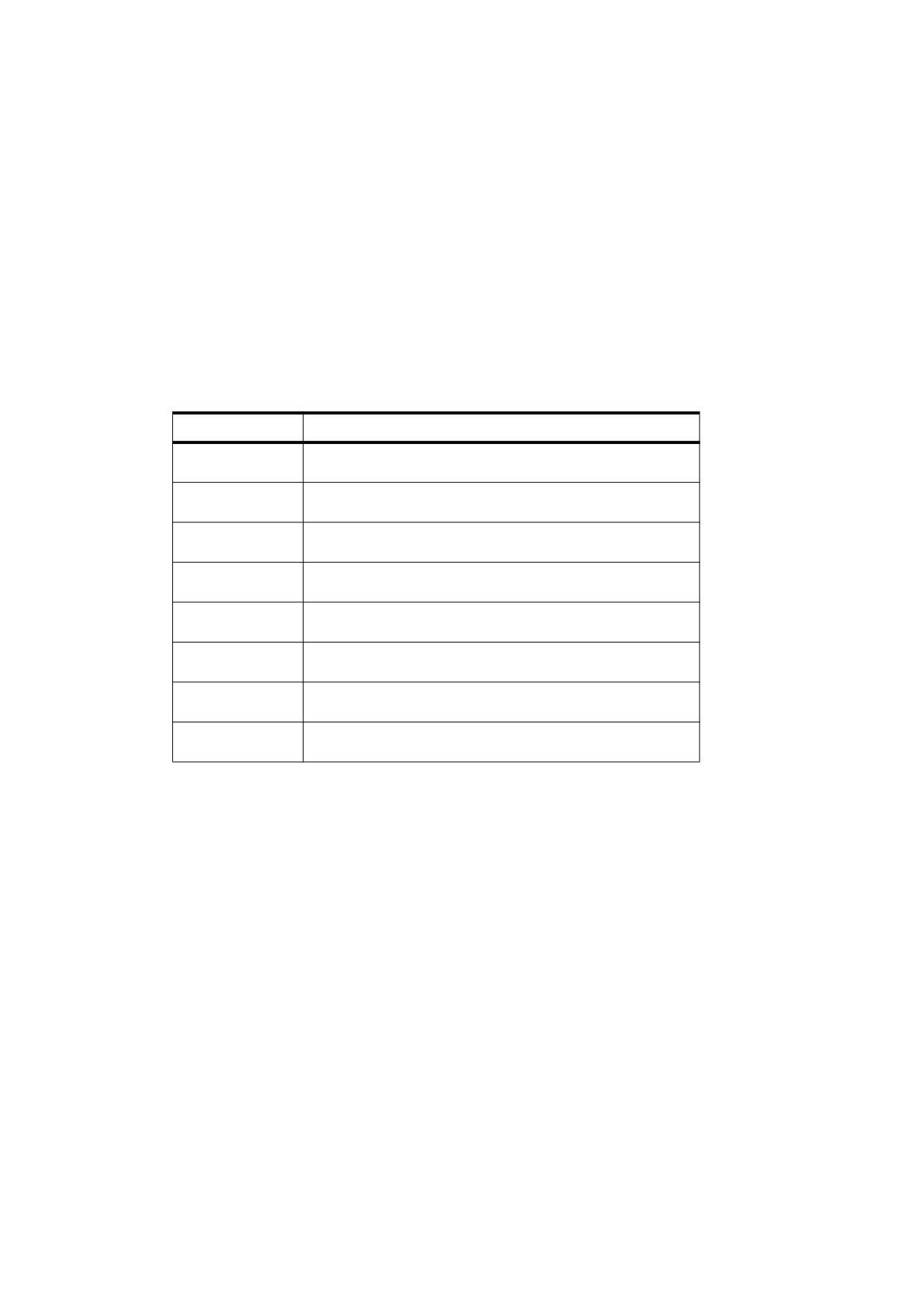
Table 132 - Additional entries specific to a type 10 halftone dictionary
Key
Type
Value
Type
name
(Optional) The type of PDF object that this dictionary describes; if
present, shall be Halftone for a halftone dictionary.
HalftoneType
integer
(Required) A code identifying the halftone type that this dictionary
describes; shall be 10 for this type of halftone.
HalftoneName
byte string
(Optional) The name of the halftone dictionary.
Xsquare
integer
(Required) The side of square X, in device pixels; see below.
Ysquare
integer
(Required) The side of square Y, in device pixels; see below.
TransferFunction
function or
(Optional) A transfer function, which shall override the current
name
transfer function in the graphics state for the same component.
This entry shall be present if the dictionary is a component of a type
5 halftone (see “Type 5 Halftones” in 10.5.5.6) and represents
either a nonprimary or nonstandard primary colour component (see
10.4, "Transfer Functions"). The name Identity may be used to
specify the identity function.
The Xsquare and Ysquare entries shall specify the dimensions of the two squares in device pixels. The stream
shall contain Xsquare 2 + Ysquare 2 bytes, each representing a single threshold value. The contents of square
X shall be specified first, followed by those of square Y. Threshold values within each square shall be defined in
device space in the same order as image samples in image space (see Figure 34), with the first value at device
coordinates (0, 0) and horizontal coordinates changing faster than vertical coordinates.
10.5.5.5
Type 16 Halftones
Like type 10, a type 16 halftone (PDF 1.3) defines a halftone screen with a threshold array and allows nonzero
screen angles. In type 16, however, each element of the threshold array shall be 16 bits wide instead of 8. This
allows the threshold array to distinguish 65,536 levels of colour rather than only 256 levels. The threshold array
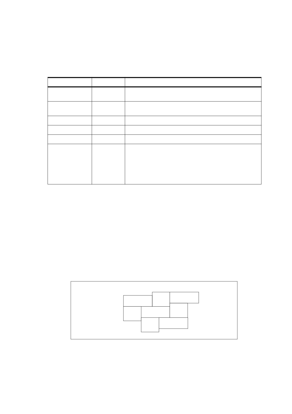
may consist of either one rectangle or two rectangles. If two rectangles are specified, they shall tile the device
space as shown in Figure 53. The last row in the first rectangle shall be immediately adjacent to the first row in
the second and shall start in the same column.
Width
Height
Width ´ Height
Height2
Width2 ´
Height2
Width2
Figure 53 - Tiling of device space in a type 16 halftone
A type 16 halftone, like type 6 and type 10, shall be represented as a stream containing the threshold values,
with the parameters defining the halftone specified by entries in the stream dictionary. This dictionary may
contain the entries shown in Table 133 in addition to the usual entries common to all streams (see Table 5). The
313
dictionary’s Width and Height entries define the dimensions of the first (or only) rectangle. The dimensions of
the second, optional rectangle are defined by the optional entries Width2 and Height2. Each threshold value
shall be represented as 2 bytes, with the high-order byte first. The stream shall contain 2 × Width × Height
bytes if there is only one rectangle or
2 × (Width × Height + Width2 × Height2) bytes if there are two
rectangles. The contents of the first rectangle are specified first, followed by those of the second rectangle.
Threshold values within each rectangle shall be defined in device space in the same order as image samples in
image space (see Figure 34), with the first value at device coordinates (0, 0) and horizontal coordinates
changing faster than vertical coordinates.
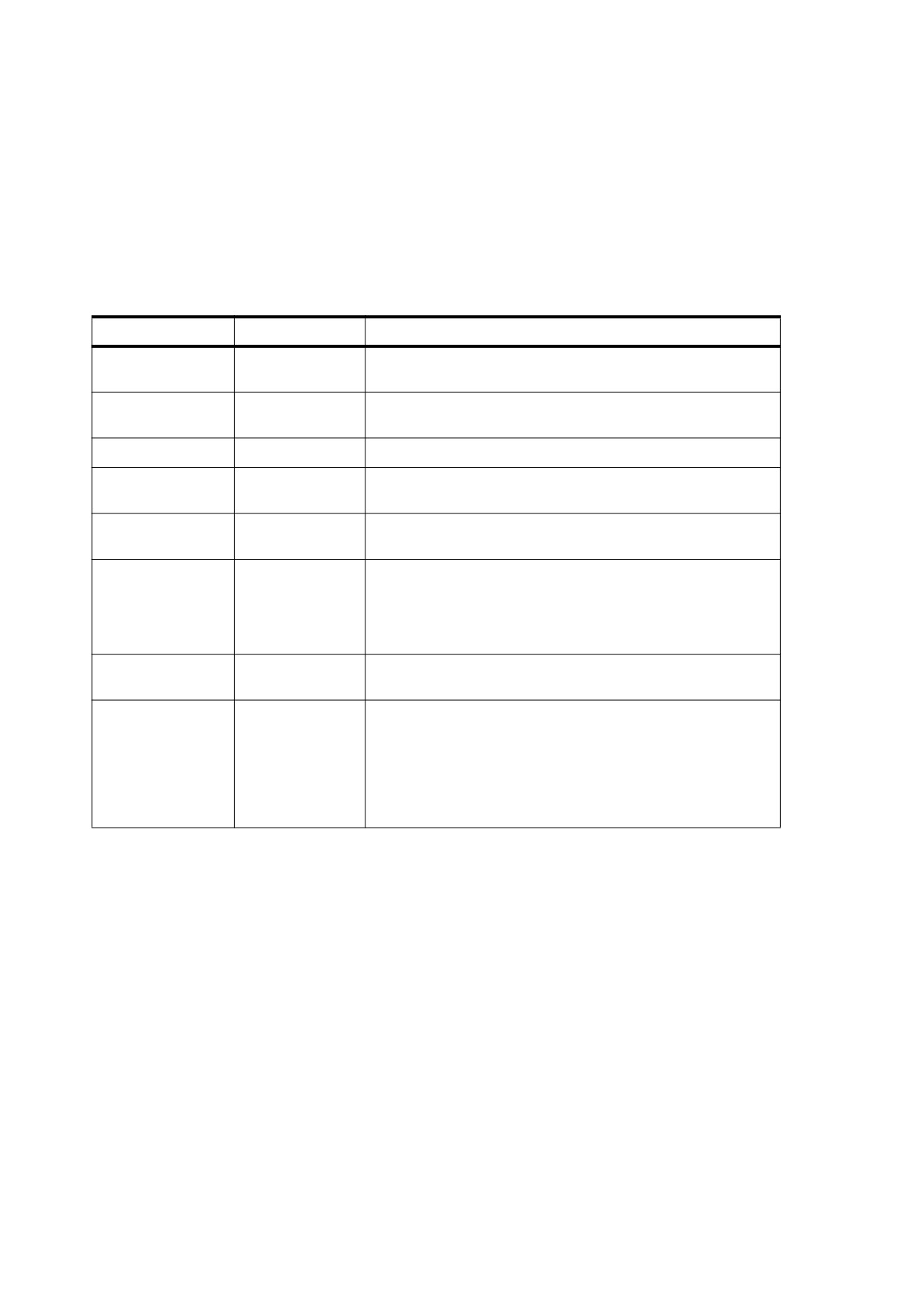
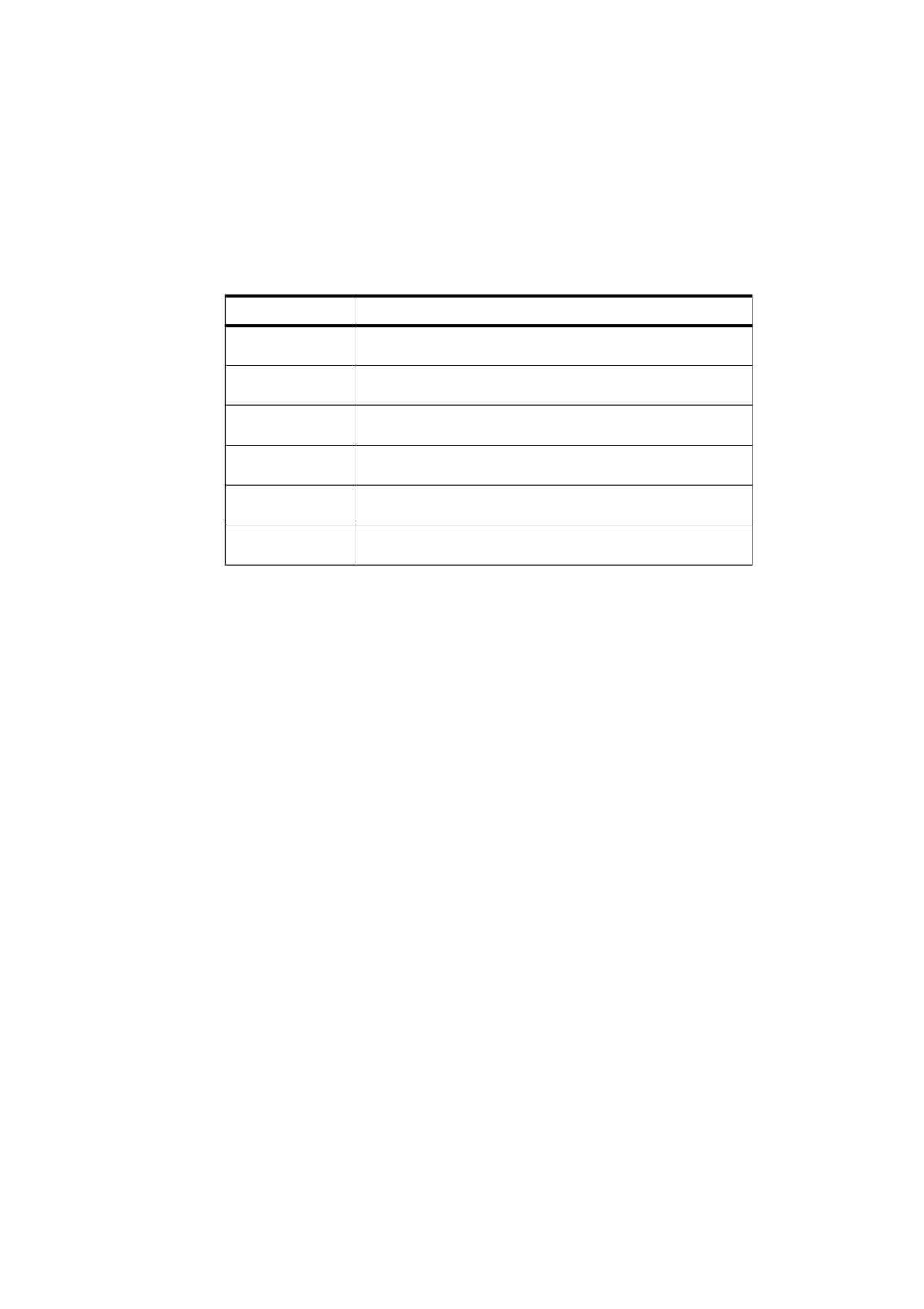
Table 133 - Additional entries specific to a type 16 halftone dictionary
Key
Type
Value
Type
name
(Optional) The type of PDF object that this dictionary describes;
if present, shall be Halftone for a halftone dictionary.
HalftoneType
integer
(Required) A code identifying the halftone type that this
dictionary describes; shall be 16 for this type of halftone.
HalftoneName
byte string
(Optional) The name of the halftone dictionary.
Width
integer
(Required) The width of the first
(or only) rectangle in the
threshold array, in device pixels.
Height
integer
(Required) The height of the first (or only) rectangle in the
threshold array, in device pixels.
Width2
integer
(Optional) The width of the optional second rectangle in the
threshold array, in device pixels. If this entry is present, the
Height2 entry shall be present as well. If this entry is absent, the
Height2 entry shall also be absent, and the threshold array has
only one rectangle.
Height2
integer
(Optional) The height of the optional second rectangle in the
threshold array, in device pixels.
TransferFunction
function or name
(Optional) A transfer function, which shall override the current
transfer function in the graphics state for the same component.
This entry shall be present if the dictionary is a component of a
type
5 halftone
(see
10.5.5.6, "Type
5 Halftones") and
represents either a nonprimary or nonstandard primary colour
component (see 10.4, "Transfer Functions"). The name Identity
may be used to specify the identity function.
10.5.5.6
Type 5 Halftones
Some devices, particularly colour printers, require separate halftones for each individual colorant. Also, devices
that can produce named separations may require individual halftones for each separation. Halftone dictionaries
of type 5 allow individual halftones to be specified for an arbitrary number of colorants or colour components.
A type 5 halftone dictionary (Table 134) is a composite dictionary containing independent halftone definitions
for multiple colorants. Its keys shall be name objects representing the names of individual colorants or colour
components. The values associated with these keys shall be other halftone dictionaries, each defining the
halftone screen and transfer function for a single colorant or colour component. The component halftone
dictionaries shall not be of halftone type 5.
314
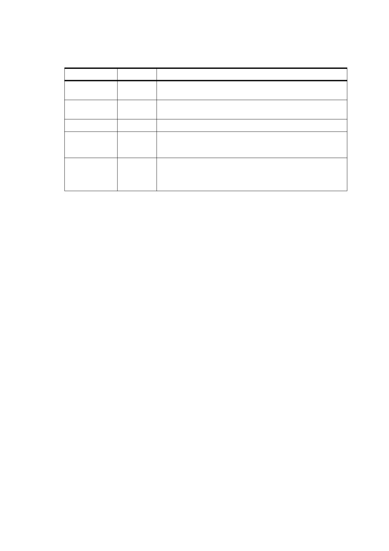
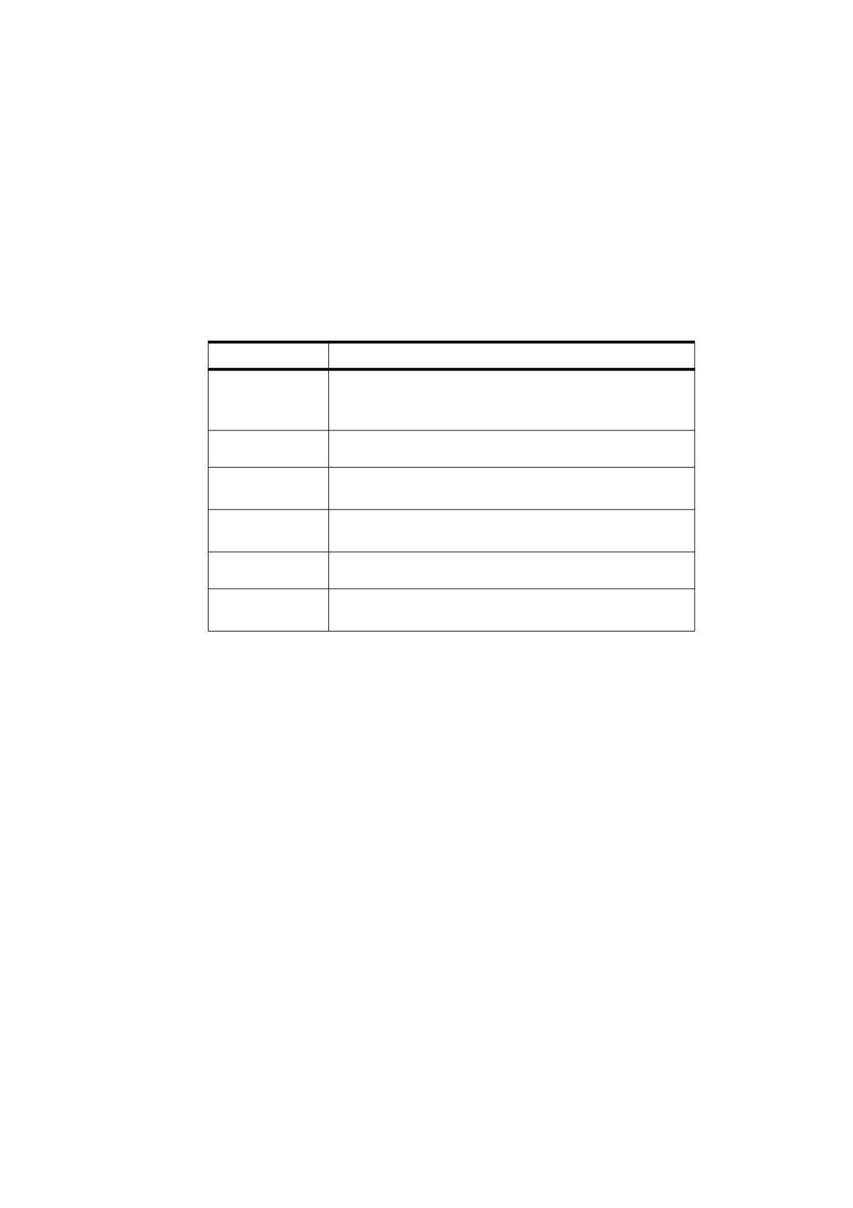
Table 134 - Entries in a type 5 halftone dictionary
Key
Type
Value
Type
name
(Optional) The type of PDF object that this dictionary describes; if
present, shall be Halftone for a halftone dictionary.
HalftoneType
number
(Required) A code identifying the halftone type that this dictionary
describes; shall be 5 for this type of halftone.
HalftoneName
byte string
(Optional) The name of the halftone dictionary.
any colorant
dictionary
(Required, one per colorant) The halftone corresponding to the
name
or stream
colorant or colour component named by the key. The halftone may be
of any type other than 5.
Default
dictionary
(Required) A halftone to be used for any colorant or colour component
or stream
that does not have an entry of its own. The value shall not be 5. If there
are any nonprimary colorants, the default halftone shall have a transfer
function.
The colorants or colour components represented in a type 5 halftone dictionary (aside from the Default entry)
fall into two categories:
•
Primary colour components for the standard native device colour spaces (Gray for DeviceGray; Red,
Green, and Blue for DeviceRGB; Cyan, Magenta, Yellow, and Black for DeviceCMYK;).
•
Nonstandard colour components for use as spot colorants in Separation and DeviceN colour spaces.
Some of these may also be used as process colorants if the native colour space is nonstandard.
When a halftone dictionary of some other type appears as the value of an entry in a type 5 halftone dictionary,
it shall apply only to the single colorant or colour component named by that entry’s key. This is in contrast to
such a dictionary’s being used as the current halftone parameter in the graphics state, which shall apply to all
colour components. If nonprimary colorants are requested when the current halftone is defined by any means
other than a type 5 halftone dictionary, the gray halftone screen and transfer function shall be used for all such
colorants.
EXAMPLE
In this example, the halftone dictionaries for the colour components and for the default all use the same
spot function. In this example, the halftone dictionaries for the colour components and for the default all
use the same spot function.
27 0 obj
<< /Type /Halftone
/HalftoneType 5
/Cyan 31 0 R
/Magenta 32 0 R
/Yellow 33 0 R
/Black 34 0 R
/Default
35 0 R
>>
endobj
31 0 obj
<< /Type /Halftone
/HalftoneType 1
/Frequency 89.827
/Angle 15
/SpotFunction /Round
/AccurateScreens true
>>
endobj
32 0 obj
315
<< /Type /Halftone
/HalftoneType 1
/Frequency 89.827
/Angle 75
/SpotFunction /Round
/AccurateScreens true
>>
endobj
33 0 obj
<< /Type /Halftone
/HalftoneType 1
/Frequency 90.714
/Angle 0
/SpotFunction /Round
/AccurateScreens true
>>
endobj
34 0 obj
<< /Type /Halftone
/HalftoneType 1
/Frequency 89.803
/Angle 45
/SpotFunction /Round
/AccurateScreens true
>>
endobj
35 0 obj
<< /Type /Halftone
/HalftoneType 1
/Frequency 90.000
/Angle 45
/SpotFunction /Round
/AccurateScreens true
>>
endobj
10.6
Scan Conversion Details
10.6.1
General
The final step of rendering shall be scan conversion. The conforming reader executes a scan conversion
algorithm to paint graphics, text, and images in the raster memory of the output device.
NOTE
The specifics of the scan conversion algorithm are not defined as part of PDF. Different implementations may
perform scan conversion in different ways; techniques that are appropriate for one device may be
inappropriate for another. Still, it is useful to have a general understanding of how scan conversion works,
particularly when creating PDF files intended for viewing on a display. At the low resolutions typical of displays,
variations of even one pixel’s width can have a noticeable effect on the appearance of painted shapes.
Most scan conversion details are not under program control, but a few are; the parameters for controlling them
are described here.
10.6.2
Flatness Tolerance
The flatness tolerance controls the maximum permitted distance in device pixels between the mathematically
correct path and an approximation constructed from straight line segments, as shown in Figure 54. Flatness
may be specified as the operand of the i operator (see Table 57) or as the value of the FL entry in a graphics
state parameter dictionary (see Table 58). It shall be a positive number.
316

NOTE 1
Smaller values yield greater precision at the cost of more computation.
NOTE 2
Although the figure exaggerates the difference between the curved and flattened paths for the sake of clarity,
the purpose of the flatness tolerance is to control the precision of curve rendering, not to draw inscribed
polygons. If the parameter’s value is large enough to cause visible straight line segments to appear, the result
is unpredictable.
Flatness error
tolerance
Figure 54 - Flatness tolerance
10.6.3
Smoothness Tolerance
The smoothness tolerance (PDF 1.3) controls the quality of smooth shading (type 2 patterns and the sh
operator) and thus indirectly controls the rendering performance. Smoothness is the allowable colour error
between a shading approximated by piecewise linear interpolation and the true value of a (possibly nonlinear)
shading function. The error shall be measured for each colour component, and the maximum independent error
shall be used. The allowable error (or tolerance) shall be expressed as a fraction of the range of the colour
component, from 0.0 to 1.0. Thus, a smoothness tolerance of 0.1 represents a tolerance of 10 percent in each
colour component. Smoothness may be specified as the value of the SM entry in a graphics state parameter
dictionary (see Table 58).
EXAMPLE
Each output device may have internal limits on the maximum and minimum tolerances attainable. setting
smoothness to 1.0 may result in an internal smoothness of 0.5 on a high-quality colour device, while
setting it to 0.0 on the same device may result in an internal smoothness of 0.01 if an error of that
magnitude is imperceptible on the device.
NOTE 1
The smoothness tolerance may also interact with the accuracy of colour conversion. In the case of a colour
conversion defined by a sampled function, the conversion function is unknown. Thus the error may be sampled
at too low a frequency, in which case the accuracy defined by the smoothness tolerance cannot be
guaranteed. In most cases, however, where the conversion function is smooth and continuous, the accuracy
should be within the specified tolerance.
NOTE 2
The effect of the smoothness tolerance is similar to that of the flatness tolerance. However, that flatness is
measured in device-dependent units of pixel width, whereas smoothness is measured as a fraction of colour
component range.
10.6.4
Scan Conversion Rules
The following rules determine which device pixels a painting operation affects. All references to coordinates
and pixels are in device space. A shape is a path to be painted with the current colour or with an image. Its
coordinates are mapped into device space but not rounded to device pixel boundaries. At this level, curves
have been flattened to sequences of straight lines, and all “insideness” computations have been performed.
Pixel boundaries always fall on integer coordinates in device space. A pixel is a square region identified by the
location of its corner with minimum horizontal and vertical coordinates. The region is half-open, meaning that it
includes its lower but not its upper boundaries. More precisely, for any point whose real-number coordinates
317
are (x, y), let i = floor (x) and j = floor (y). The pixel that contains this point is the one identified as (i, j). The
region belonging to that pixel is defined to be the set of points (x ′, y ′) such that i ≤ x ′ < i + 1 and j ≤ y′ < j + 1.
Like pixels, shapes to be painted by filling and stroking operations are also treated as half-open regions that
include the boundaries along their “floor” sides, but not along their “ceiling” sides.
A shape shall be scan-converted by painting any pixel whose square region intersects the shape, no matter
how small the intersection is. This ensures that no shape ever disappears as a result of unfavourable
placement relative to the device pixel grid, as might happen with other possible scan conversion rules. The
area covered by painted pixels shall always be at least as large as the area of the original shape. This rule
applies both to fill operations and to strokes with nonzero width. Zero-width strokes may be done in an
implementation-defined manner that may include fewer pixels than the rule implies.
NOTE 1
Normally, the intersection of two regions is defined as the intersection of their interiors. However, for purposes
of scan conversion, a filling region is considered to intersect every pixel through which its boundary passes,
even if the interior of the filling region is empty.
EXAMPLE
A zero-width or zero-height rectangle paints a line 1 pixel wide.
The region of device space to be painted by a sampled image is determined similarly to that of a filled shape,
though not identically. The conforming reader transforms the image’s source rectangle into device space and
defines a half-open region, just as for fill operations. However, only those pixels whose centres lie within the
region shall be painted. The position of the centre of such a pixel—in other words, the point whose coordinate
values have fractional parts of one-half—shall be mapped back into source space to determine how to colour
the pixel. There shall not be averaging over the pixel area;
NOTE 2
If the resolution of the source image is higher than that of device space, some source samples may not be
used.
For clipping, the clipping region consists of the set of pixels that would be included by a fill operation.
Subsequent painting operations shall affect a region that is the intersection of the set of pixels defined by the
clipping region with the set of pixels for the region to be painted.
Scan conversion of character glyphs may be performed by a different algorithm from the preceding one.
NOTE 3
That font rendering algorithm uses hints in the glyph descriptions and techniques that are specialized to glyph
rasterization.
10.6.5
Automatic Stroke Adjustment
When a stroke is drawn along a path, the scan conversion algorithm may produce lines of nonuniform
thickness because of rasterization effects. In general, the line width and the coordinates of the endpoints,
transformed into device space, are arbitrary real numbers not quantized to device pixels. A line of a given width
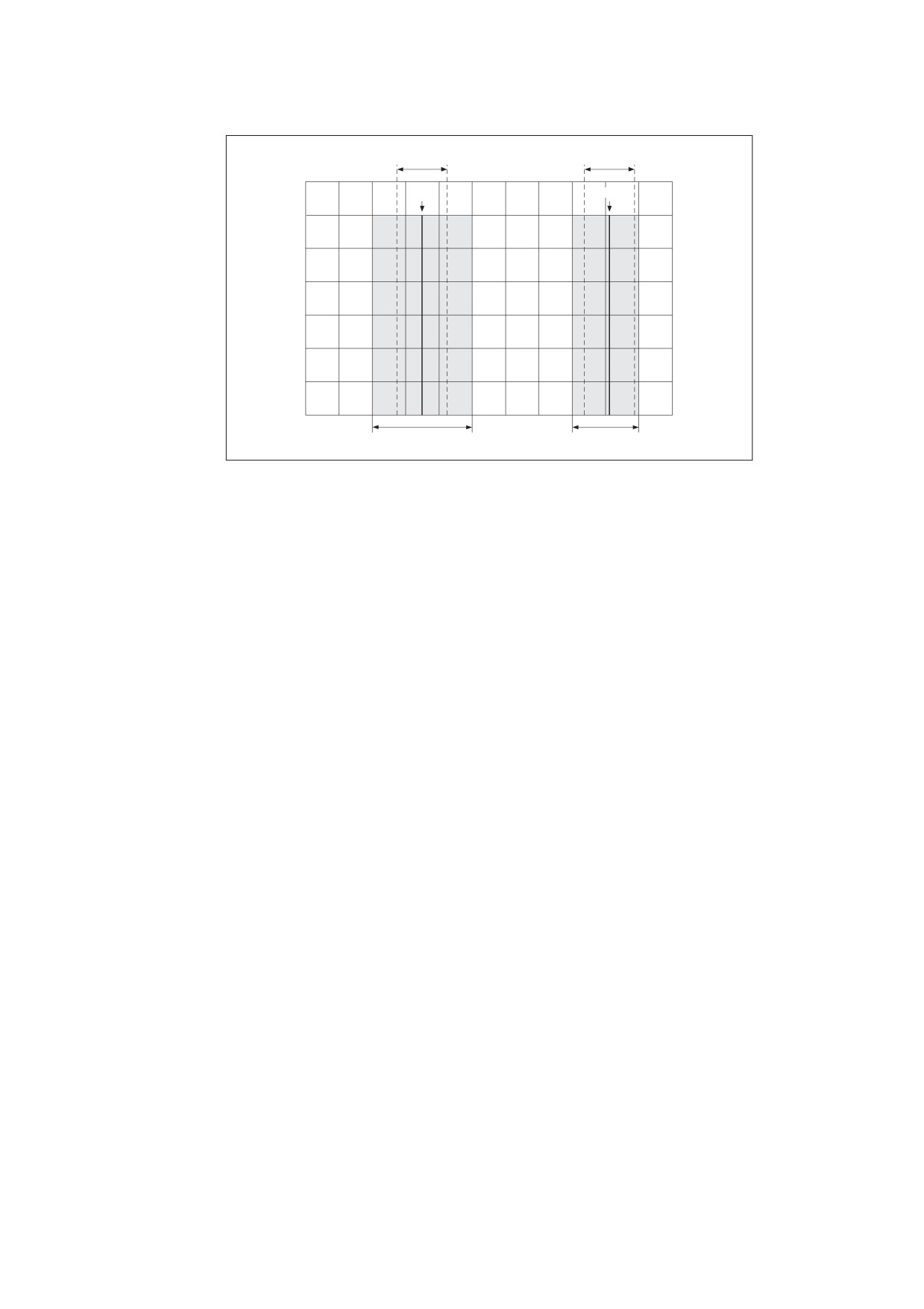
can intersect with different numbers of device pixels, depending on where it is positioned. Figure 55 illustrates
this effect.
For best results, it is important to compensate for the rasterization effects to produce strokes of uniform
thickness. This is especially important in low-resolution display applications. To meet this need, PDF 1.2
provides an optional automatic stroke adjustment feature. When stroke adjustment is enabled, the line width
and the coordinates of a stroke shall automatically be adjusted as necessary to produce lines of uniform
thickness. The thickness shall be as near as possible to the requested line width—no more than half a pixel
different.
318
Line width
Line width
Path
Path
1
pixel
Resulting line
Resulting line
Figure 55 - Rasterization without stroke adjustment
If stroke adjustment is enabled and the requested line width, transformed into device space, is less than half a
pixel, the stroke shall be rendered as a single-pixel line.
NOTE
This is the thinnest line that can be rendered at device resolution. It is equivalent to the effect produced by
setting the line width to 0 (see 10.6.4, "Scan Conversion Rules").
Because automatic stroke adjustment can have a substantial effect on the appearance of lines, PDF provides
means to control whether the adjustment shall be performed. This may be specified with the stroke adjustment
parameter in the graphics state, set by means of the SA entry in a graphics state parameter dictionary (see
8.4.5, "Graphics State Parameter Dictionaries").
319
11
Transparency
11.1
General
The PDF imaging model includes the notion of transparency. Transparent objects do not necessarily obey a
strict opaque painting model but may blend (composite) in interesting ways with other overlapping objects. This
clause describes the general transparency model but does not cover how it is implemented. At various points it
uses implementation-like descriptions to describe how things work, for the purpose of elucidating the behaviour
of the model. The actual implementation will almost certainly be different from what these descriptions might
imply.
NOTE
Transparency was added to PDF in version 1.4
The clause is organized as follows:
•
11.2, "Overview of Transparency," introduces the basic concepts of the transparency model and its
associated terminology.
•
11.3, "Basic Compositing Computations," describes the mathematics involved in compositing a single
object with its backdrop.
•
11.4, "Transparency Groups," introduces the concept of transparency groups and describes their
properties and behaviour.
•
11.5, "Soft Masks," covers the creation and use of masks to specify position-dependent shape and opacity.
•
11.6, "Specifying Transparency in PDF," describes how transparency properties are represented in a PDF
document.
•
11.7, "Colour Space and Rendering Issues," deals with some specific interactions between transparency
and other aspects of colour specification and rendering.
11.2
Overview of Transparency
The original PDF imaging model paints objects (fills, strokes, text, and images), possibly clipped by a path,
opaquely onto a page. The colour of the page at any point shall be that of the topmost enclosing object,
disregarding any previous objects it may overlap. This effect may be—and often is—realized simply by
rendering objects directly to the page in the order in which they are specified, with each object completely
overwriting any others that it overlaps.
Under the transparent imaging model, all of the objects on a page may potentially contribute to the result.
Objects at a given point may be thought of as forming a transparency stack (or stack for short). The objects
shall be arranged from bottom to top in the order in which they are specified. The colour of the page at each
point shall be determined by combining the colours of all enclosing objects in the stack according to
compositing rules defined by the transparency model.
NOTE 1
The order in which objects are specified determines the stacking order but not necessarily the order in which
the objects are actually painted onto the page. In particular, the transparency model does not require a
conforming reader to rasterize objects immediately or to commit to a raster representation at any time before
rendering the entire stack onto the page. This is important, since rasterization often causes significant loss of
information and precision that is best avoided during intermediate stages of the transparency computation.
A given object shall be composited with a backdrop. Ordinarily, the backdrop consists of the stack of all objects
that have been specified previously. The result of compositing shall then be treated as the backdrop for the
next object. However, within certain kinds of transparency groups (see “Transparency Groups”), a different
backdrop may be chosen.
320
During the compositing of an object with its backdrop, the colour at each point shall be computed using a
specified blend mode, which is a function of both the object’s colour and the backdrop colour. The blend mode
shall determine how colours interact; different blend modes may be used to achieve a variety of useful effects.
A single blend mode shall be in effect for compositing all of a given object, but different blend modes may be
applied to different objects.
Two scalar quantities called shape and opacity mediate compositing of an object with its backdrop.
Conceptually, for each object, these quantities shall be defined at every point in the plane, just as if they were
additional colour components. (In actual practice, they may be obtained from auxiliary sources rather than
being intrinsic to the object.)
Both shape and opacity vary from 0.0 (no contribution) to 1.0 (maximum contribution). At any point where either
the shape or the opacity of an object is equal to 0.0, its colour shall be undefined. At points where the shape is
equal to 0.0, the opacity shall also be undefined. The shape and opacity shall be subject to compositing rules;
therefore, the stack as a whole also has a shape and opacity at each point.
An object’s opacity, in combination with the backdrop’s opacity, shall determine the relative contributions of the
backdrop colour, the object’s colour, and the blended colour to the resulting composite colour. The object’s
shape shall then determine the degree to which the composite colour replaces the backdrop colour. Shape
values of 0.0 and 1.0 identify points that lie outside and inside a conventional sharp-edged object; intermediate
values are useful in defining soft-edged objects.
Shape and opacity are conceptually very similar. In fact, they can usually be combined into a single value,
called alpha, which controls both the colour compositing computation and the fading between an object and its
backdrop. However, there are a few situations in which they shall be treated separately; see 11.4.6, "Knockout
Groups."
NOTE 2
Raster-based implementations may need to maintain a separate shape parameter to do anti-aliasing properly;
it is therefore convenient to have shape as an explicit part of the model.
One or more consecutive objects in a stack may be collected together into a transparency group (often referred
to hereafter simply as a group). The group as a whole may have various properties that modify the compositing
behaviour of objects within the group and their interactions with its backdrop. An additional blend mode, shape,
and opacity may also be associated with the group as a whole and used when compositing it with its backdrop.
Groups may be nested within other groups, forming a tree-structured hierarchy.
EXAMPLE
Figure L.16 in Annex L illustrates the effects of transparency grouping. In the upper two figures, three
coloured circles are painted as independent objects with no grouping. At the upper left, the three objects
are painted opaquely (opacity = 1.0); each object completely replaces its backdrop (including previously
painted objects) with its own colour. At the upper right, the same three independent objects are painted
with an opacity of 0.5, causing them to composite with each other and with the gray and white backdrop.
In the lower two figures, the three objects are combined as a transparency group. At the lower left, the
individual objects have an opacity of 1.0 within the group, but the group as a whole is painted in the
Normal blend mode with an opacity of 0.5. The objects thus completely overwrite each other within the
group, but the resulting group then composites transparently with the gray and white backdrop. At the
lower right, the objects have an opacity of 0.5 within the group and thus composite with each other. The
group as a whole is painted against the backdrop with an opacity of 1.0 but in a different blend mode
(HardLight), producing a different visual effect.
The colour result of compositing a group may be converted to a single-component luminosity value and treated
as a soft mask. Such a mask may then be used as an additional source of shape or opacity values for
subsequent compositing operations. When the mask is used as a shape, this technique is known as soft
clipping; it is a generalization of the current clipping path in the opaque imaging model (see “Clipping Path
Operators”).
The notion of current page is generalized to refer to a transparency group consisting of the entire stack of
objects placed on the page, composited with a backdrop that is pure white and fully opaque. Logically, this
entire stack shall then be rasterized to determine the actual pixel values to be transmitted to the output device.
321

NOTE 3
In contexts where a PDF page is treated as a piece of artwork to be placed on some other page it is treated not
as a page but as a group, whose backdrop may be defined differently from that of a page.
11.3
Basic Compositing Computations
11.3.1
General
This sub-clause describes the basic computations for compositing a single object with its backdrop. These
computations are extended in 11.4, "Transparency Groups," to cover groups consisting of multiple objects.
11.3.2
Basic Notation for Compositing Computations
In general, variable names in this clause consisting of a lowercase letter denote a scalar quantity, such as an
opacity. Uppercase letters denote a value with multiple scalar components, such as a colour. In the descriptions
of the basic colour compositing computations, colour values are generally denoted by the letter C, with a
mnemonic subscript indicating which of several colour values is being referred to; for instance, Cs stands for
“source colour.” Shape and opacity values are denoted respectively by the letters f (for “form factor”) and q (for
“opaqueness”)—again with a mnemonic subscript, such as qs for “source opacity.” The symbol α (alpha) stands
for a product of shape and opacity values.
In certain computations, one or more variables may have undefined values; for instance, when opacity is equal
to zero, the corresponding colour is undefined. A quantity can also be undefined if it results from division by
zero. In any formula that uses such an undefined quantity, the quantity has no effect on the ultimate result
because it is subsequently multiplied by zero or otherwise cancelled out. It is significant that while any arbitrary
value may be chosen for such an undefined quantity, the computation shall not malfunction because of
exceptions caused by overflow or division by zero. The further convention that 0 ÷ 0 = 0 should also be
adopted.
11.3.3
Basic Compositing Formula
The primary change in the imaging model to accommodate transparency is in how colours are painted. In the
transparent model, the result of painting (the result colour) is a function of both the colour being painted (the
source colour) and the colour it is painted over (the backdrop colour). Both of these colours may vary as a
function of position on the page; however, this sub-clause focuses on some fixed point on the page and
assumes a fixed backdrop and source colour.
This computation uses two other parameters: alpha, which controls the relative contributions of the backdrop
and source colours, and the blend function, which specifies how they shall be combined in the painting
operation. The resulting basic colour compositing formula (or just basic compositing formula for short) shall
determine the result colour produced by the painting operation:
⎛
αs⎞
αs
Cr
=
⎜1
- -----⎟
×
Cb
+
-----
×[
(
1
-
αb
)× Cs + αb× B(Cb, Cs
)]
α
αr
⎝
r
⎠
where the variables have the meanings shown in Table 135.
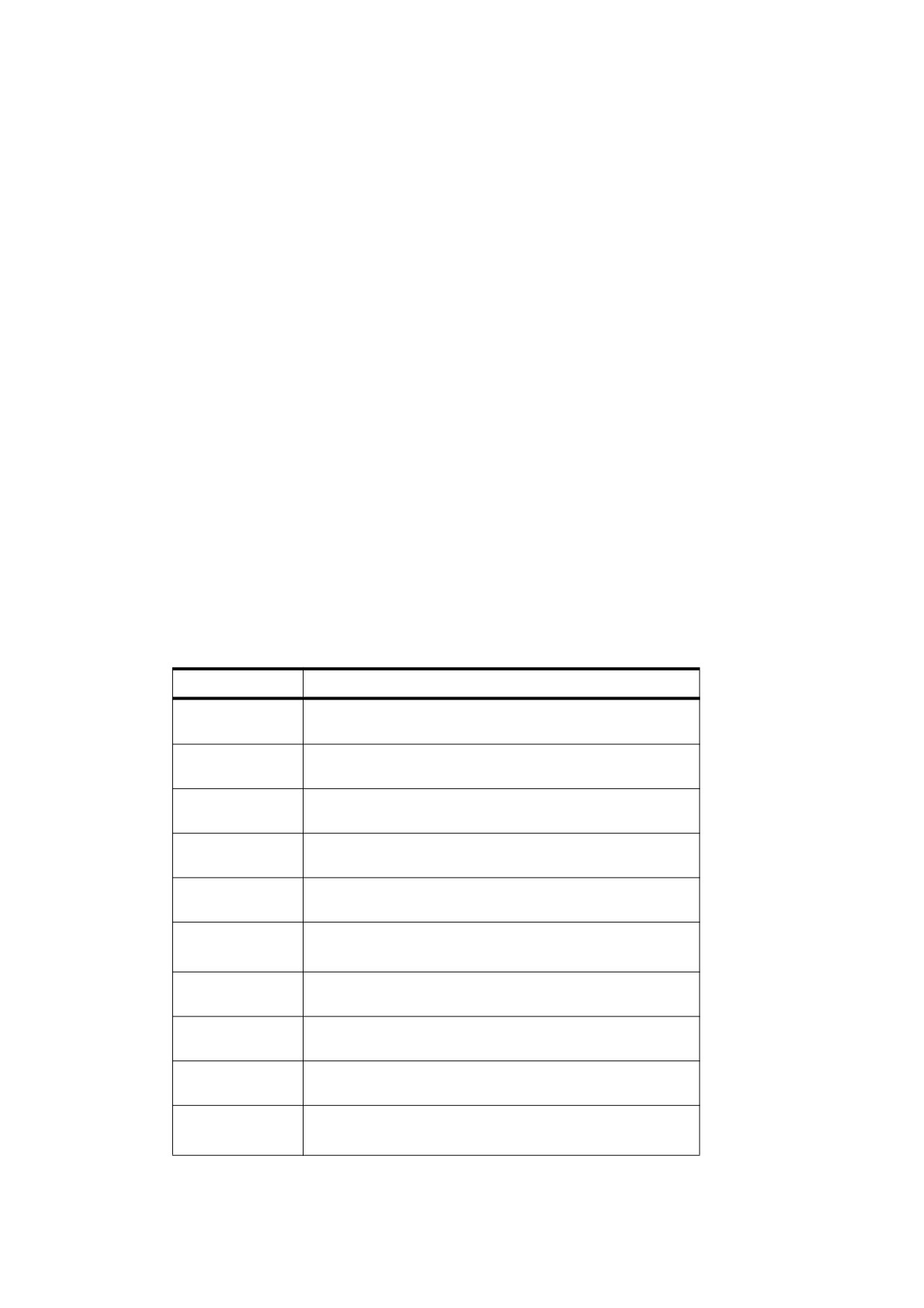
Table 135 - Variables used in the basic compositing formula
Variable
Meaning
Cb
Backdrop colour
Source colour
Cs
Cr
Result colour
322

Table 135 - Variables used in the basic compositing formula (continued)
Variable
Meaning
αb
Backdrop alpha
αs
Source alpha
αr
Result alpha
B(Cb,Cs)
Blend function
This formula represents a simplified form of the compositing formula in which the shape and opacity values are
combined and represented as a single alpha value; the more general form is presented later. This function is
based on the over operation defined in the article “Compositing Digital Images,” by Porter and Duff (see
the Bibliography), extended to include a blend mode in the region of overlapping coverage. The following sub-
clauses elaborate on the meaning and implications of this formula.
11.3.4
Blending Colour Space
The compositing formula shown in 11.3.3, "Basic Compositing Formula," represents a vector function: the
colours it operates on are represented in the form of n-element vectors, where n denotes the number of
components required by the colour space in used in the compositing process. The ith component of the result
colour Cr shall be obtained by applying the compositing formula to the ith components of the constituent
colours Cb , Cs , and B (Cb, Cs ). The result of the computation thus depends on the colour space in which the
colours are represented. For this reason, the colour space used for compositing, called the blending colour
space, is explicitly made part of the transparent imaging model. When necessary, backdrop and source colours
shall be converted to the blending colour space before the compositing computation.
Of the PDF colour spaces described in Section 8.6, the following shall be supported as blending colour spaces:
•
DeviceGray
•
DeviceRGB
•
DeviceCMYK
•
CalGray
•
CalRGB
•
ICCBased colour spaces equivalent to the preceding (including calibrated CMYK)
The Lab space and ICCBased spaces that represent lightness and chromaticity separately (such as L*a*b*,
L*u*v*, and HSV) shall not be used as blending colour spaces because the compositing computations in such
spaces do not give meaningful results when applied separately to each component. In addition, an ICCBased
space used as a blending colour space shall be bidirectional; that is, the ICC profile shall contain both AToB
and BToA transformations.
The blending colour space shall be consulted only for process colours. Although blending may also be done on
individual spot colours specified in a Separation or DeviceN colour space, such colours shall not be converted
to a blending colour space (except in the case where they first revert to their alternate colour space, as
described under Section 8.6.6.4 and “DeviceN Colour Spaces”). Instead, the specified colour components shall
be blended individually with the corresponding components of the backdrop.
The blend functions for the various blend modes are defined such that the range for each colour component
shall be 0.0 to 1.0 and that the colour space shall be additive. When performing blending operations in
323
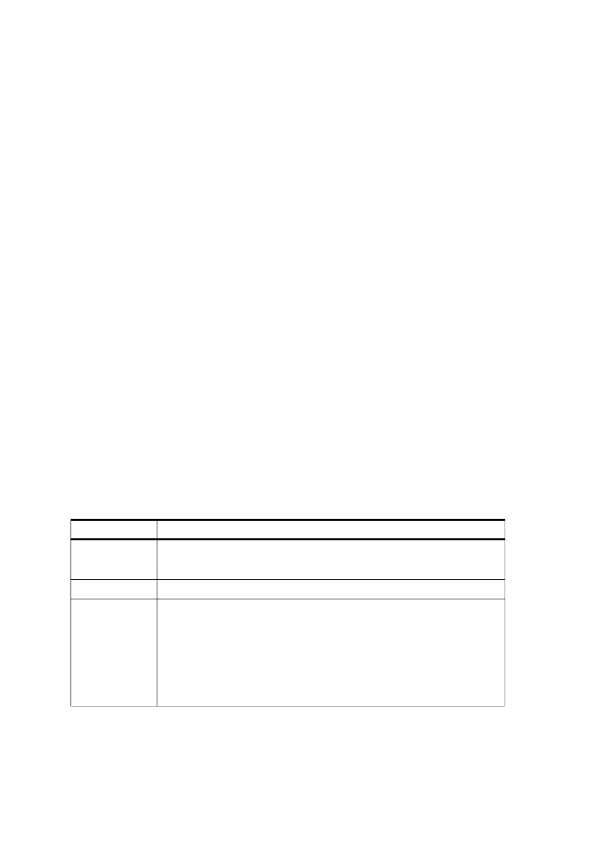
subtractive colour spaces (DeviceCMYK, Separation, and DeviceN), the colour component values shall be
complemented (subtracted from 1.0) before the blend function is applied and the results of the function shall
then be complemented back before being used.
NOTE
This adjustment makes the effects of the various blend modes numerically consistent across all colour spaces.
However, the actual visual effect produced by a given blend mode still depends on the colour space. Blending
in a device colour space produces device-dependent results, whereas in a CIE-based space it produces
results that are consistent across all devices. See 11.7, "Colour Space and Rendering Issues," for additional
details concerning colour spaces.
11.3.5
Blend Mode
In principle, any function of the backdrop and source colours that yields another colour, Cr, for the result may be
used as a blend function B (Cb , Cs), in the compositing formula to customize the blending operation. PDF
defines a standard set of named blend functions, or blend modes, listed in Tables 136 and 137. Figures L.18
and L.19 in Annex L illustrate the resulting visual effects for RGB and CMYK colours, respectively.
A blend mode is termed separable if each component of the result colour is completely determined by the
corresponding components of the constituent backdrop and source colours—that is, if the blend mode function
B is applied separately to each set of corresponding components:
cr
=
B(cb, cs
)
where the lowercase variables cr, c
, and c
, and Cs ,
b
s denote corresponding components of the colours Cr, Cb
expressed in additive form. A separable blend mode may be used with any colour space, since it applies
independently to any number of components. Only separable blend modes shall be used for blending spot
colours.
NOTE 1
Theoretically, a blend mode could have a different function for each colour component and still be separable;
however, none of the standard PDF blend modes have this property.
Table 136 lists the standard separable blend modes available in PDF and the algorithms/formulas that shall be
used in the calculation of blended colours.
Table 136 - Standard separable blend modes
Name
Result
Normal
B(cb,cs) = cs
NOTE
Selects the source colour, ignoring the backdrop.
Compatible
Same as Normal. This mode exists only for compatibility and should not be used.
Multiply
B(cb,cs) = cb× cs
NOTE 1
Multiplies the backdrop and source colour values.
NOTE 2
The result colour is always at least as dark as either of the two
constituent colours. Multiplying any colour with black produces black;
multiplying with white leaves the original colour unchanged. Painting
successive overlapping objects with a colour other than black or white
produces progressively darker colours.
324
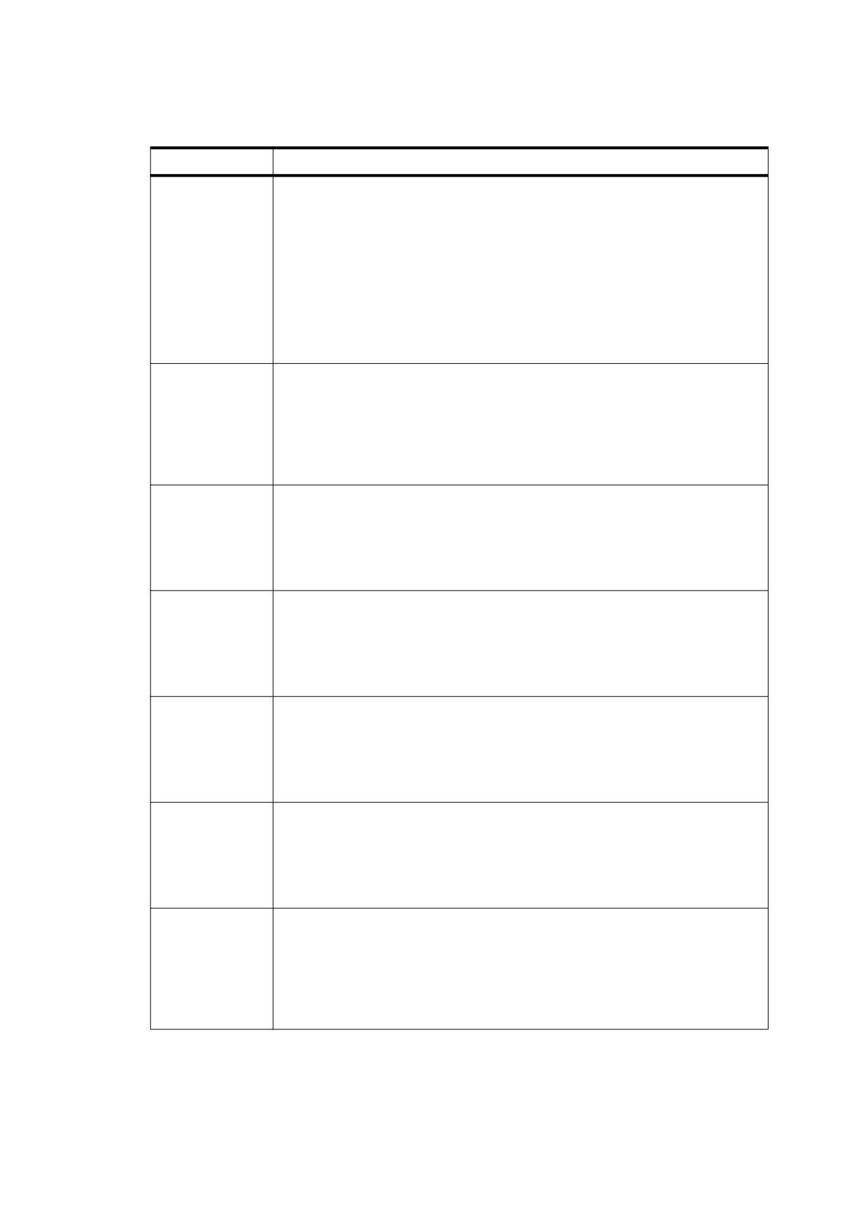
Table 136 - Standard separable blend modes (continued)
Name
Result
Screen
B(cb,cs)
=
1
– [
(
1
-
cb
)
×
(
1
–
cs
)]
=
cb + cs
-
(
cb × cs
)
NOTE 3
Multiplies the complements of the backdrop and source colour values,
then complements the result.
NOTE 4
The result colour is always at least as light as either of the two
constituent colours. Screening any colour with white produces white;
screening with black leaves the original colour unchanged. The effect
is similar to projecting multiple photographic slides simultaneously
onto a single screen.
Overlay
(
)
=
HardLight(cs, cb)
NOTE 5
Multiplies or screens the colours, depending on the backdrop colour
value. Source colours overlay the backdrop while preserving its
highlights and shadows. The backdrop colour is not replaced but is
mixed with the source colour to reflect the lightness or darkness of the
backdrop.
Darken
B(cb,cs)
=
min(cb, cs
)
NOTE 6
Selects the darker of the backdrop and source colours.
NOTE 7
The backdrop is replaced with the source where the source is darker;
otherwise, it is left unchanged.
Lighten
B(cb,cs)
=
max(cb, cs
)
NOTE 8
Selects the lighter of the backdrop and source colours.
NOTE 9
The backdrop is replaced with the source where the source is lighter;
otherwise, it is left unchanged.
ColorDodge
min(1, cb
⁄
(
1
–
cs
))
if cs
<
1
⎧
B(cb,cs)
=
⎨
1
if c
=
⎩
s
NOTE 10
Brightens the backdrop colour to reflect the source colour. Painting
with black produces no changes.
ColorBurn
1
–
min(1,
(
1
-
cb
)⁄ cs)
if cs
>
0
⎧
B(cb,cs)
=
⎨
⎩0
if c
=
s
NOTE 11
Darkens the backdrop colour to reflect the source colour. Painting
with white produces no change.
HardLight
Multiply(cb, 2
×
cs)
if cs ≤ 0.5
⎧
B(cb,cs)
=
⎨
Screen(c
×
cs
-
1)
if cs > 0.5
⎩
b, 2
NOTE 12
Multiplies or screens the colours, depending on the source colour
value. The effect is similar to shining a harsh spotlight on the
backdrop.
325
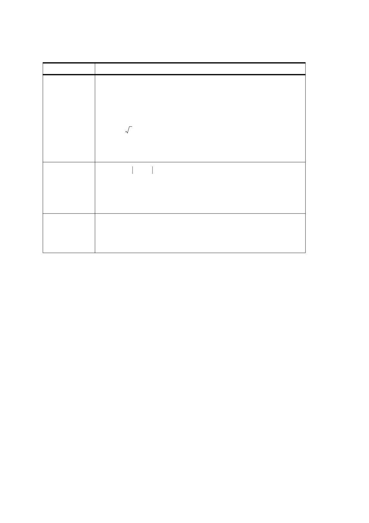
Table 136 - Standard separable blend modes (continued)
Name
Result
SoftLight
cb
–
(
1
–
2
×
cs
)× cb
×
(
1
–
cb
)
if cs ≤ 0.5
⎧
(
)
=
⎨
⎩c
+
(
2
×
cs
-
1
)
×
(
(
) cb
)
if cs > 0.5
b
where
⎧((16 × x - 12) × x + 4) × x
if x ≤ 0.25
D(x)
=
⎨
⎩
x
if x > 0.25
NOTE 13
Darkens or lightens the colours, depending on the source colour
value. The effect is similar to shining a diffused spotlight on the
backdrop.
Difference
B(cb,cs)
=
cb – cs
NOTE 14
Subtracts the darker of the two constituent colours from the lighter
colour:
NOTE 15
Painting with white inverts the backdrop colour; painting with black
produces no change.
Exclusion
(
)
=
cb + cs
–
2
×
cb
×
c
s
NOTE 16
Produces an effect similar to that of the Difference mode but lower in
contrast. Painting with white inverts the backdrop colour; painting with
black produces no change.
Table 137 lists the standard nonseparable blend modes. Since the nonseparable blend modes consider all
colour components in combination, their computation depends on the blending colour space in which the
components are interpreted. They may be applied to all multiple-component colour spaces that are allowed as
blending colour spaces (see “Blending Colour Space”).
NOTE 2
All of these blend modes conceptually entail the following steps:
a) Convert the backdrop and source colours from the blending colour space to an intermediate HSL (hue-
saturation-luminosity) representation.
b) Create a new colour from some combination of hue, saturation, and luminosity components selected from
the backdrop and source colours.
c) Convert the result back to the original (blending) colour space.
However, the following formulas given do not actually perform these conversions. Instead, they start with
whichever colour (backdrop or source) is providing the hue for the result; then they adjust this colour to have
the proper saturation and luminosity.
The nonseparable blend mode formulas make use of several auxiliary functions. These functions operate on
colours that are assumed to have red, green, and blue components. Blending of CMYK colour spaces requires
special treatment, as described in this sub-clause.
These functions shall have the following definitions:
Lum(C)
=
0.3
×
Cred
+
0.59
×
Cgreen
+
0.11
×
Cblue
326

SetLum(C, l)
let d
=
l
-
Lum(C)
Cred
=
Cred + d
Cgreen
=
Cgreen + d
Cblue
=
Cblue + d
returnClipColor(C)
ClipColor(C)
let l
=
Lum(C)
let n
=
min(Cred, Cgreen, Cblue)
let x
=
max(Cred, Cgreen, Cblue)
if n
<
0.0
Cred
=
l
+
(((
Cred
-
l
)×l)⁄(l-n))
Cgreen
=
l
+
(((
Cgreen
-
l
)×l)⁄(l-n))
Cblue
=
l
+
(((
Cblue
-
l
)×l)⁄(l-n))
if x
>
1.0
Cred
=
l
+
(((
Cred
-
l
)×(1-l))⁄(x-l))
Cgreen
=
l
+
(((
Cgreen
-
l
)×(1-l))⁄(x-l))
Cblue
=
l
+
(((
Cblue
-
l
)×(1-l))⁄(x-l))
return C
Sat(C)
=
max(Cred, Cgreen, Cblue) min(Cred, Cgreen, Cblue)
The subscripts min, mid, and max (in the next function) refer to the colour components having the minimum,
middle, and maximum values upon entry to the function.
SetSat(C, s)
if Cmax > Cmin
Cmid
=
(
(
(
Cmid Cmin
)×s)⁄(Cmax – Cmin
))
Cmax
=
s
else
Cmid = Cmax
=
0.0
Cmin
=
0.0
return C
Table 137 - Standard nonseparable blend modes
Name
Result
Hue
B(Cb,Cs) = SetLum(SetSa
(
,
(
)), Lum(Cb))
NOTE 1
Creates a colour with the hue of the source colour and the saturation
and luminosity of the backdrop colour.
Saturation
B(Cb,Cs) = SetLum(SetSa
(
,
(
)), Lum(Cb))
NOTE 2
Creates a colour with the saturation of the source colour and the hue
and luminosity of the backdrop colour. Painting with this mode in an
area of the backdrop that is a pure gray (no saturation) produces no
change.
327
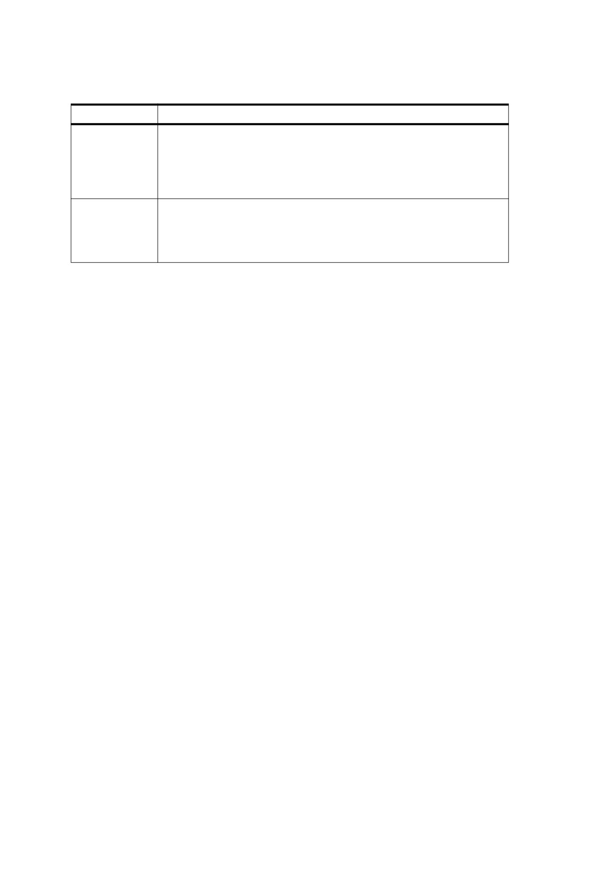
Table 137 - Standard nonseparable blend modes (continued)
Name
Result
Color
B(Cb,Cs) = SetLum(Cs,Lum(Cb))
NOTE 3
Creates a colour with the hue and saturation of the source colour and
the luminosity of the backdrop colour. This preserves the gray levels
of the backdrop and is useful for colouring monochrome images or
tinting colour images.
Luminosity
B(Cb,Cs) = SetLum(Cb,Lu
(
))
NOTE 4
Creates a colour with the luminosity of the source colour and the hue
and saturation of the backdrop colour. This produces an inverse effect
to that of the Color mode.
The formulas in this sub-clause apply to RGB spaces. Blending in CMYK spaces (including both DeviceCMYK
and ICCBased calibrated CMYK spaces) shall be handled in the following way:
•
The C, M, and Y components shall be converted to their complementary R, G, and B components in the
usual way. The preceding formulas shall be applied to the RGB colour values. The results shall be
converted back to C, M, and Y.
•
For the K component, the result shall be the K component of Cb for the Hue, Saturation, and Color blend
modes; it shall be the K component of Cs for the Luminosity blend mode.
11.3.6
Interpretation of Alpha
The colour compositing formula
⎛
αs⎞
αs
Cr
=
⎜1
- -----⎟
×
Cb
+
-----
×[
(
1
-
αb
)× Cs + αb× B(Cb, Cs
)]
α
αr
⎝
r
⎠
produces a result colour that is a weighted average of the backdrop colour, the source colour, and the blended
B (Cb , Cs ) term, with the weighting determined by the backdrop and source alphas αβ and αs . For the simplest
blend mode, Normal, defined by
·
B(cb,
cs
)
=
cs
the compositing formula collapses to a simple weighted average of the backdrop and source colours, controlled
by the backdrop and source alpha values. For more interesting blend functions, the backdrop and source
alphas control whether the effect of the blend mode is fully realized or is toned down by mixing the result with
the backdrop and source colours.
The result alpha, αρ , actually represents a computed result, described in 11.3.7, "Shape and Opacity
Computations." The result colour shall be normalized by the result alpha, ensuring that when this colour and
alpha are subsequently used together in another compositing operation, the colour’s contribution is correctly
represented.
NOTE 1
If αρ is zero, the result colour is undefined.
NOTE 2
The preceding formula represents a simplification of the following formula, which presents the relative
contributions of backdrop, source, and blended colours in a more straightforward way:
αr × Cr
=
[
(
1
-
αs
)× αb× Cb
]
+
[
(
1
-
αb
)× αs× Cs
]
+[
αb
×
αs
×
B
(
Cb
,
Cs
)
328
(The simplification requires a substitution based on the alpha compositing formula, which is presented in the
next sub-clause.) Thus, mathematically, the backdrop and source alphas control the influence of the backdrop
and source colours, respectively, while their product controls the influence of the blend function. An alpha
value of αs = 0.0 or αβ = 0.0 results in no blend mode effect; setting αs = 1.0 and αβ = 1.0 results in maximum
blend mode effect.
11.3.7
Shape and Opacity Computations
11.3.7.1
General
As stated earlier, the alpha values that control the compositing process shall be defined as the product of
shape and opacity:
αb = fb × qb
αr = fr × qr
αs = fs × qs
This sub-clause examines the various shape and opacity values individually. Once again, keep in mind that
conceptually these values are computed for every point on the page.
11.3.7.2
Source Shape and Opacity
Shape and opacity values may come from several sources. The transparency model provides for three
independent sources for each. However, the PDF representation imposes some limitations on the ability to
specify all of these sources independently (see “Specifying Shape and Opacity”).
•
Object shape. Elementary objects such as strokes, fills, and text have an intrinsic shape, whose value shall
be 1.0 for points inside the object and 0.0 outside. Similarly, an image with an explicit mask (see “Explicit
Masking”) has a shape that shall be 1.0 in the unmasked portions and 0.0 in the masked portions. The
shape of a group object shall be the union of the shapes of the objects it contains.
NOTE 1
Mathematically, elementary objects have “hard” edges, with a shape value of either 0.0 or 1.0 at every point.
However, when such objects are rasterized to device pixels, the shape values along the boundaries may be
anti-aliased, taking on fractional values representing fractional coverage of those pixels. When such anti-
aliasing is performed, it is important to treat the fractional coverage as shape rather than opacity.
•
Mask shape. Shape values for compositing an object may be taken from an additional source, or soft
mask, independent of the object itself, as described in 11.5, "Soft Masks."
NOTE 2
The use of a soft mask to modify the shape of an object or group, called soft clipping, can produce effects such
as a gradual transition between an object and its backdrop, as in a vignette.
•
Constant shape. The source shape may be modified at every point by a scalar shape constant.
NOTE 3
This is merely a convenience, since the same effect could be achieved with a shape mask whose value is the
same everywhere.
•
Object opacity. Elementary objects have an opacity of 1.0 everywhere. The opacity of a group object shall
be the result of the opacity computations for all of the objects it contains.
•
Mask opacity. Opacity values, like shape values, may be provided by a soft mask independent of the object
being composited.
•
Constant opacity. The source opacity may be modified at every point by a scalar opacity constant.
NOTE 4
It is useful to think of this value as the “current opacity,” analogous to the current colour used when painting
elementary objects.
329
All of the shape and opacity inputs shall have values in the range 0.0 to 1.0 (inclusive), with a default value of
1.0.
The three shape inputs shall be multiplied together, producing an intermediate value called the source shape.
fs
=
fj
×
fm × fk
The three opacity inputs shall be multiplied together, producing an intermediate value called the source opacity.
qs
=
qj × qm × qk
Where the variables have the meanings shown in Table 138.
Table 138 - Variables used in the source shape and opacity formulas
Variable
Meaning
fs
Source shape
fj
Object shape
fm
Mask shape
fk
Constant shape
qs
Source opacity
qj
Object opacity
qm
Mask opacity
qk
Constant opacity
NOTE 5
The effect of each of these inputs is that the painting operation becomes more transparent as the input values
decreases.
When an object is painted with a tiling pattern, the object shape and object opacity for points in the object’s
interior are determined by those of corresponding points in the pattern, rather than being 1.0 everywhere (see
“Patterns and Transparency”).
11.3.7.3
Result Shape and Opacity
In addition to a result colour, the painting operation also shall compute an associated result shape and result
opacity. These computations shall be based on the union function
Union ( b, s ) = 1 - [(1 - b) × (1 - s)]
= b + s - (b×s)
where b and s shall be the backdrop and source values to be composited.
NOTE 1
This is a generalization of the conventional concept of union for opaque shapes, and it can be thought of as an
“inverted multiplication”—a multiplication with the inputs and outputs complemented. The result tends toward
1.0: if either input is 1.0, the result is 1.0.
The result shape and opacity shall be given by
330
fr
=
Union(fb, fs
)
Union(fb × qb, fs × qs )
qr
= ---------------------------------------------------------
f
r
where the variables have the meanings shown in Table 139.
Table 139 - Variables used in the result shape and opacity formulas
Variable
Meaning
fr
Result shape
fb
Backdrop shape
fs
Source shape
qr
Result opacity
Backdrop opacity
qb
qs
Source opacity
These formulas shall be interpreted as follows:
•
The result shape shall be the union of the backdrop and source shapes.
•
The result opacity shall be the union of the backdrop and source opacities, weighted by their respective
shapes. The result shall then be divided by (normalized by) the result shape.
NOTE 2
Since alpha is just the product of shape and opacity, it can easily be shown that
αr
=
Union(αb,
αs)
This formula can be used whenever the independent shape and opacity are not needed.
11.3.8
Summary of Basic Compositing Computations
This sub-clause is a summary of all the computations presented in this sub-clause. They are given in an order
such that no variable is used before it is computed; also, some of the formulas have been rearranged to
simplify them. See Tables 135, 138, and 139 for the meanings of the variables used in these formulas.
Union ( b, s ) = 1 - [(1 - b) × (1 - s)]
= b + s - (b×s)
fs
=
fj
×
fm × fk
qs
=
qj
×
qm ×qk
·
fr
=
Union(fb,
fs
)
331
αb = fb × qb
αs
=
fs
×
qs
αr = Union(αb, αs )
αr
q
= -----
r
f
r
⎛
αs⎞
αs
Cr
=
⎜1
- -----⎟
×
Cb
+
-----
×[
(
1
-
αb
)× Cs + αb× B(Cb, Cs
)]
α
αr
⎝
r
⎠
11.4
Transparency Groups
11.4.1
General
A transparency group is a sequence of consecutive objects in a transparency stack that shall be collected
together and composited to produce a single colour, shape, and opacity at each point. The result shall then be
treated as if it were a single object for subsequent compositing operations. Groups may be nested within other
groups to form a tree-structured group hierarchy.
NOTE
This facilitates creating independent pieces of artwork, each composed of multiple objects, and then combining
them, possibly with additional transparency effects applied during the combination.
The objects contained within a group shall be treated as a separate transparency stack called the group stack.
The objects in the stack shall be composited against an initial backdrop (discussed later), producing a
composite colour, shape, and opacity for the group as a whole. The result is an object whose shape is the
union of the shapes of its constituent objects and whose colour and opacity are the result of the compositing
operations. This object shall then be composited with the group’s backdrop in the usual way.
In addition to its computed colour, shape, and opacity, the group as a whole may have several further attributes:
•
All of the input variables that affect the compositing computation for individual objects may also be applied
when compositing the group with its backdrop. These variables include mask and constant shape, mask
and constant opacity, and blend mode.
•
The group may be isolated or non-isolated, which shall determine the initial backdrop against which its
stack is composited.
•
The group may be knockout or non-knockout, which shall determine whether the objects within its stack
are composited with one another or only with the group’s backdrop.
•
An isolated group may specify its own blending colour space, independent of that of the group’s backdrop.
•
Instead of being composited onto the current page, a group’s results may be used as a source of shape or
opacity values for creating a soft mask (see “Soft Masks”).
11.4.2
Notation for Group Compositing Computations
This sub-clause introduces some notation for dealing with group compositing. Subsequent sub-clauses
describe the group compositing formulas for a non-isolated, non-knockout group and the special properties of
isolated and knockout groups.
332

Since we are now dealing with multiple objects at a time, it is useful to have some notation for distinguishing
among them. Accordingly, the variables introduced earlier are altered to include a second-level subscript
denoting an object’s position in the transparency stack.
stands for the source colour of the ith object in the stack. The subscript 0 represents the initial backdrop;
Cs
i
subscripts 1 to n denote the bottommost to topmost objects in an n-element stack. In addition, the subscripts b
and r are dropped from the variables Cb , fβ , qβ , αβ , Cr, fρ, qρ, and αρ ; other variables retain their mnemonic
subscripts.
These conventions permit the compositing formulas to be restated as recurrence relations among the elements
of a stack. For instance, the result of the colour compositing computation for object i is denoted by Ci (formerly
Cr ). This computation takes as one of its inputs the immediate backdrop colour, which is the result of the colour
compositing computation for object i − 1; this is denoted by Ci − 1 (formerly Cb ).
The revised formulas for a simple n-element stack (not including any groups) shall be, for i = 1, … , n:
fs
=
fj
×
fm
×
fk
i
i
i
i
qs
=
qj
×
qm
×
qk
i
i
i
i
αs
=
fs
×
qs
i
i
i
αi
=
Union(αi-1,
αs
)
i
fi
=
Union(fi-1,
fs
)
i
αi
qi
= -----
f
i
αs
αs
⎛
⎞
i
i
Ci
=
⎜1
- ------
⎟
×
Ci-1
+
×[(
1
-
αi-1
)× Cs
+
αi-1
×
Bi (Ci-1
,
C
)]
si
α
αi
i
⎝
i
⎠
where the variables have the meanings shown in Table 140.
NOTE
Compare these formulas with those shown in 11.3.8, "Summary of Basic Compositing Computations."
Table 140 - Revised variables for the basic compositing formulas
Variable
Meaning
fs
Source shape for object i
i
fj
Object shape for object i
i
Mask shape for object i
fm
i
fk
Constant shape for object i
i
fi
Result shape after compositing object i
333

Table 140 - Revised variables for the basic compositing formulas (continued)
Variable
Meaning
qs
Source opacity for object i
i
qj
Object opacity for object i
i
qm
Mask opacity for object i
i
Constant opacity for object i
qk
i
qi
Result opacity after compositing object i
αs
Source alpha for object i
i
αi
Result alpha after compositing object i
Cs
Source colour for object i
i
Ci
Result colour after compositing object i
Bi(Ci-1, Cs
)
Blend function for object i
i
11.4.3
Group Structure and Nomenclature
As stated earlier, the elements of a group shall be treated as a separate transparency stack, referred to as the
group stack. These objects shall be composited against a selected initial backdrop and the resulting colour,
shape, and opacity shall then be treated as if they belonged to a single object. The resulting object is in turn
composited with the group’s backdrop in the usual way.
NOTE
This computation entails interpreting the stack as a tree. For an n-element group that begins at position i in the
stack, it treats the next n objects as an n-element substack, whose elements are given an independent
numbering of 1 to n. These objects are then removed from the object numbering in the parent (containing)
stack and replaced by the group object, numbered i, followed by the remaining objects to be painted on top of
the group, renumbered starting at i + 1. This operation applies recursively to any nested subgroups.
The term element (denoted Ei ) refers to a member of some group; it can be either an individual object or a
contained subgroup.
From the perspective of a particular element in a nested group, there are three different backdrops of interest:
•
The group backdrop is the result of compositing all elements up to but not including the first element in the
group. (This definition is altered if the parent group is a knockout group; see 11.4.6, "Knockout Groups")
•
The initial backdrop is a backdrop that is selected for compositing the group’s first element. This is either
the same as the group backdrop (for a non-isolated group) or a fully transparent backdrop (for an isolated
group).
•
The immediate backdrop is the result of compositing all elements in the group up to but not including the
current element.
When all elements in a group have been composited, the result shall be treated as if the group were a single
object, which shall then be composited with the group backdrop. This operation shall occur whether the initial
334
backdrop chosen for compositing the elements of the group was the group backdrop or a transparent backdrop.
A conforming reader shall ensure that the backdrop’s contribution to the overall result is applied only once.
11.4.4
Group Compositing Computations
The colour and opacity of a group shall be defined by the group compositing function:
〈 C, f, α 〉
=
Composite(C0, α0,
G
)
where the variables have the meanings shown in Table 141.
Table 141 - Arguments and results of the group compositing function
Variable
Meaning
G
The transparency group: a compound object consisting of all
elements E1, … , En of the group—the n constituent objects’
colours, shapes, opacities, and blend modes
C0
Colour of the group’s backdrop
C
Computed colour of the group, which shall be used as the
source colour when the group is treated as an object
Computed shape of the group, which shall be used as the
f
object shape when the group is treated as an object
α0
Alpha of the group’s backdrop
α
Computed alpha of the group, which shall be used as the
object alpha when the group is treated as an object
NOTE 1
The opacity is not given explicitly as an argument or result of this function. Almost all of the computations use
the product of shape and opacity (alpha) rather than opacity alone; therefore, it is usually convenient to work
directly with shape and alpha rather than shape and opacity. When needed, the opacity can be computed by
dividing the alpha by the associated shape.
The result of applying the group compositing function shall then be treated as if it were a single object, which in
turn is composited with the group’s backdrop according to the formulas defined in this sub-clause. In those
formulas, the colour, shape, and alpha (C, f, and α) calculated by the group compositing function shall be used,
respectively, as the source colour Cs , the object shape fj , and the object alpha αj .
The group compositing formulas for a non-isolated, non-knockout group are defined as follows:
•
Initialization:
fg
=
α
= 0.0
g0
0
•
For each group element Ei ∈ G (i = 1, … , n):
⎧
Composite(Ci-1,
αi-1,
Ei)
if Ei is a group
〈
〉
=
⎨
Csi, fji, αji
⎩
intrinsic color, shape, and (shape × opacity) of Ei
otherwise
fs
=
fj
×
fm
×
f
ki
i
i
i
αs
=
αj
×
( fm
×
qm
)
×
( fk
×
q
)
ki
i
i
i
i
i
335
fg
=
Union(fg
,
fs
)
i
i-1
i
αg
=
Union(αg
,
αs
)
i
i-1
i
αi
=
Union(α0,αg
)
i
αs
αs
⎛
⎞
i
i
Ci
=
⎜1
- ------
⎟
×
Ci-1
+
×((
1
-
αi-1
)× Cs
+
αi-1
×
Bi (Ci-1
,
C
))
si
α
αi
i
⎝
i
⎠
•
Result:
⎛
α0
⎞
C = Cn + (Cn –C0)
×
⎜
-------- –α0⎟
α
⎝
gn
⎠
f
=
fg
n
α = αg
n
where the variables have the meanings shown in Table 142 (in addition to those in Table 141).
For an element E
Cs
,
fj
, and
αj
are intrinsic
i that is an elementary object, the colour, shape, and alpha values
i
i
i
attributes of the object. For an element that is a group, the group compositing function shall be applied
recursively to the subgroup and the resulting C, f, and α values shall be used for itsCs,
fj
, and
αj
in the
i
i
i
calculations for the parent group.
Table 142 - Variables used in the group compositing formulas
Variable
Meaning
Ei
Element i of the group: a compound variable representing the
element’s colour, shape, opacity, and blend mode
fs
Source shape for element Ei
i
fj
Object shape for element Ei
i
fm
Mask shape for element Ei
i
fk
Constant shape for element Ei
i
fg
Group shape: the accumulated source shapes of group
i
elements E1 to Ei , excluding the initial backdrop
qm
Mask opacity for element Ei
i
Constant opacity for element Ei
qk
i
αs
Source alpha for element Ei
i
αj
Object alpha for element Ei : the product of its object shape
i
and object opacity
336
Table 142 - Variables used in the group compositing formulas (continued)
Variable
Meaning
αg
Group alpha: the accumulated source alphas of group
i
elements E1 to Ei, excluding the initial backdrop
αi
Accumulated alpha after compositing element Ei , including
the initial backdrop
Cs
Source colour for element Ei
i
Ci
Accumulated colour after compositing element Ei , including
the initial backdrop
Bi(Ci-1, Cs
)
Blend function for element Ei
i
NOTE 2
The elements of a group are composited onto a backdrop that includes the group’s initial backdrop. This is
done to achieve the correct effects of the blend modes, most of which are dependent on both the backdrop and
source colours being blended. This feature is what distinguishes non-isolated groups from isolated groups,
discussed in the next sub-clause.
NOTE 3
Special attention should be directed to the formulas at the end that compute the final results C, f, and α, of the
group compositing function. Essentially, these formulas remove the contribution of the group backdrop from
the computed results. This ensures that when the group is subsequently composited with that backdrop
(possibly with additional shape or opacity inputs or a different blend mode), the backdrop’s contribution is
included only once.
For colour, the backdrop removal is accomplished by an explicit calculation, whose effect is essentially the
reverse of compositing with the Normal blend mode. The formula is a simplification of the following formulas,
which present this operation more intuitively:
(1
-
αg
)× α0
φb
= --------------------------------------
Union(α
,
α
)
0
g
n
Cn – φb × C0
C
= -------------------------------
1
-
φ
b
where
φb
is the backdrop fraction, the relative contribution of the backdrop colour to the overall colour.
NOTE 4
For shape and alpha, backdrop removal is accomplished by maintaining two sets of variables to hold the
accumulated values. There is never any need to compute the corresponding complete shape, fi , that includes
the backdrop contribution.
The group shape and alpha,
fg
and
αg
, shall accumulate only the shape and alpha of the group elements,
i
i
excluding the group backdrop. Their final values shall become the group results returned by the group
compositing function. The complete alpha, αi , includes the backdrop contribution as well; its value is used in
the colour compositing computations.
NOTE 5
As a result of these corrections, the effect of compositing objects as a group is the same as that of compositing
them separately (without grouping) if the following conditions hold:
The group is non-isolated and has the same knockout attribute as its parent group (see 11.4.5, "Isolated
Groups," and “Knockout Groups”).
When compositing the group’s results with the group backdrop, the Normal blend mode is used, and the
shape and opacity inputs are always 1.0.
337
11.4.5
Isolated Groups
An isolated group is one whose elements shall be composited onto a fully transparent initial backdrop rather
than onto the group’s backdrop. The resulting source colour, object shape, and object alpha for the group shall
be therefore independent of the group backdrop. The only interaction with the group backdrop shall occur when
the group’s computed colour, shape, and alpha are composited with it.
In particular, the special effects produced by the blend modes of objects within the group take into account only
the intrinsic colours and opacities of those objects; they shall not be influenced by the group’s backdrop.
EXAMPLE
Applying the Multiply blend mode to an object in the group produces a darkening effect on other objects
lower in the group’s stack but not on the group’s backdrop.
Figure L.17 in Annex L illustrates this effect for a group consisting of four overlapping circles in a light gray
colour (C = M = Y = 0.0; K = 0.15). The circles are painted within the group with opacity 1.0 in the
Multiply blend mode; the group itself is painted against its backdrop in Normal blend mode. In the top
row, the group is isolated and thus does not interact with the rainbow backdrop. In the bottom row, the
group is non-isolated and composites with the backdrop. The figure also illustrates the difference between
knockout and non-knockout groups (see “Knockout Groups”).
NOTE 1
Conceptually, the effect of an isolated group could be represented by a simple object that directly specifies a
colour, shape, and opacity at each point. This flattening of an isolated group is sometimes useful for importing
and exporting fully composited artwork in applications. Furthermore, a group that specifies an explicit blending
colour space shall be an isolated group.
For an isolated group, the group compositing formulas shall be altered by adding one statement to the
initialization:
α0 = 0.0
if the group is isolated
That is, the initial backdrop on which the elements of the group are composited shall be transparent rather than
inherited from the group’s backdrop.
NOTE 2
This substitution also makes C0 undefined, but the normal compositing formulas take care of that. Also, the
result computation for C automatically simplifies to C = Cn , since there is no backdrop contribution to be
factored out.
11.4.6
Knockout Groups
In a knockout group, each individual element shall be composited with the group’s initial backdrop rather than
with the stack of preceding elements in the group. When objects have binary shapes (1.0 for inside, 0.0 for
outside), each object shall overwrite (knocks out) the effects of any earlier elements it overlaps within the same
group. At any given point, only the topmost object enclosing the point shall contribute to the result colour and
opacity of the group as a whole.
EXAMPLE
Figure L.17 in Annex L about 11.4.5, "Isolated Groups," illustrates the difference between knockout and
non-knockout groups. In the left column, the four overlapping circles are defined as a knockout group and
therefore do not composite with each other within the group. In the right column, the circles form a non-
knockout group and thus do composite with each other. In each column, the upper and lower figures
depict an isolated and a non-isolated group, respectively.
NOTE 1
This model is similar to the opaque imaging model, except that the “topmost object wins” rule applies to both
the colour and the opacity. Knockout groups are useful in composing a piece of artwork from a collection of
overlapping objects, where the topmost object in any overlap completely obscures those beneath. At the same
time, the topmost object interacts with the group’s initial backdrop in the usual way, with its opacity and blend
mode applied as appropriate.
The concept of knockout is generalized to accommodate fractional shape values. In that case, the immediate
backdrop shall be only partially knocked out and shall be replaced by only a fraction of the result of compositing
the object with the initial backdrop.
338
The restated group compositing formulas deal with knockout groups by introducing a new variable, b, which is
a subscript that specifies which previous result to use as the backdrop in the compositing computations: 0 in a
knockout group or i − 1 in a non-knockout group. When b = i − 1, the formulas simplify to the ones given in
11.4.4, "Group Compositing Computations."
In the general case, the computation shall proceed in two stages:
a) Composite the source object with the group’s initial backdrop, disregarding the object’s shape and using a
source shape value of 1.0 everywhere. This produces unnormalized temporary alpha and colour results, αt
and Ct .
NOTE 2
For colour, this computation is essentially the same as the unsimplified colour compositing formula given in
11.3.6, "Interpretation of Alpha," but using a source shape of 1.0.
αt
=
Union(αg
,
qs
)
b
i
Ct
=
(1
-
qs
)× αb× Cb
+
qs
×((
1
-
αb
)× Cs
+
αb ×Bi (Cb,Cs
))
i
i
i
i
b) Compute a weighted average of this result with the object’s immediate backdrop, using the source shape
as the weighting factor. Then normalize the result colour by the result alpha:
αg
=
(1
-
fs
)× αg
+
fs
×
αt
i
i
i-1
i
αi
=
Union(α0,αg
)
i
(1
-
fs
)× αi-1
×
Ci-1
+
fs
×
Ct
i
Ci
= -----------------
α
i
This averaging computation shall be performed for both colour and alpha.
NOTE 3
The preceding formulas show this averaging directly. The formulas in 11.4.8, "Summary of Group Compositing
Computations," are slightly altered to use source shape and alpha rather than source shape and opacity,
avoiding the need to compute a source opacity value explicitly.
NOTE 4
Ct in Group Compositing Computations is slightly different from the preceding Ct: it is premultiplied by
fs
i
NOTE 5
The extreme values of the source shape produce the straightforward knockout effect. That is, a shape value of
1.0 (inside) yields the colour and opacity that result from compositing the object with the initial backdrop. A
shape value of 0.0 (outside) leaves the previous group results unchanged.
The existence of the knockout feature is the main reason for maintaining a separate shape value rather than
only a single alpha that combines shape and opacity. The separate shape value shall be computed in any
group that is subsequently used as an element of a knockout group.
A knockout group may be isolated or non-isolated; that is, isolated and knockout are independent attributes. A
non-isolated knockout group composites its topmost enclosing element with the group’s backdrop. An isolated
knockout group composites the element with a transparent backdrop.
NOTE 6
When a non-isolated group is nested within a knockout group, the initial backdrop of the inner group is the
same as that of the outer group; it is not the immediate backdrop of the inner group. This behaviour, although
perhaps unexpected, is a consequence of the group compositing formulas when b = 0.
339
11.4.7
Page Group
All of the elements painted directly onto a page—both top-level groups and top-level objects that are not part of
any group—shall be treated as if they were contained in a transparency group P, which in turn is composited
with a context-dependent backdrop. This group is called the page group.
The page group shall be treated in one of two distinctly different ways:
•
Ordinarily, the page shall be imposed directly on an output medium, such as paper or a display screen. The
page group shall be treated as an isolated group, whose results shall then be composited with a backdrop
colour appropriate for the medium. The backdrop is nominally white, although varying according to the
actual properties of the medium. However, some conforming readers may choose to provide a different
backdrop, such as a checker board or grid to aid in visualizing the effects of transparency in the artwork.
•
A “page” of a PDF file may be treated as a graphics object to be used as an element of a page of some
other document.
EXAMPLE
This case arises, for example, when placing a PDF file containing a piece of artwork produced by a
drawing program into a page layout produced by a layout program. In this situation, the PDF “page” is not
composited with the media colour; instead, it is treated as an ordinary transparency group, which can be
either isolated or non-isolated and is composited with its backdrop in the normal way.
The remainder of this sub-clause pertains only to the first use of the page group, where it is to be imposed
directly on the medium.
The colour C of the page at a given point shall be defined by a simplification of the general group compositing
formula:
·
〈
Cg,fg,αg
〉
=
Composite(U, 0, P)
C
=
(
1
-
αg
)×W + αg×Cg
where the variables have the meanings shown in Table 143. The first formula computes the colour and alpha
for the group given a transparent backdrop—in effect, treating P as an isolated group. The second formula
composites the results with the context-dependent backdrop (using the equivalent of the Normal blend mode).
Table 143 - Variables used in the page group compositing formulas
Variable
Meaning
P
The page group, consisting of all elements E1, … , En in the
page’s top-level stack
Cg
Computed colour of the page group
fg
Computed shape of the page group
αg
Computed alpha of the page group
C
Computed colour of the page
W
Initial colour of the page
(nominally white but may vary
depending on the properties of the medium or the needs of
the application)
U
An undefined colour
(which is not used, since the α0
argument of Composite is 0)
340
If not otherwise specified, the page group’s colour space shall be inherited from the native colour space of the
output device—that is, a device colour space, such as DeviceRGB or DeviceCMYK. An explicit colour space
should be specified, particularly a CIE-based space, to ensure more predictable results of the compositing
computations within the page group. In this case, all page-level compositing shall be done in the specified
colour space, and the entire result shall then be converted to the native colour space of the output device
before being composited with the context-dependent backdrop.
NOTE
This case also arises when the page is not actually being rendered but is converted to a flattened
representation in an opaque imaging model, such as PostScript.
11.4.8
Summary of Group Compositing Computations
This sub-clause is a restatement of the group compositing formulas that also takes isolated groups and
knockout groups into account. See Tables 141 and 142 in 11.4.4, "Group Compositing Computations," for the
meanings of the variables.
〈 C, f, α 〉
=
Composite(C0, α0,
G
)
Initialization:
fg
=
αg
=
0
0
0
α0 = 0
if the group is isolated
For each group element Ei ∈ G (i = 1, … , n):
⎧
0
if the group is knockout
b
=
⎨
⎩i-1
otherwise
⎧
Composite(Cb, αb, Ei )
if Ei is a group
〈
〉
=
⎨
Csi, fji, αji
⎩
intrinsic color, shape, and (shape × opacity) of Ei
otherwise
fs
=
fj
×
fm
×
fk
i
i
i
i
αs
=
αj
×
( fm
×
qm
)
×
( fk
×
q
)
ki
i
i
i
i
i
fg
=
Union(fg
,
fs
)
i
i-1
i
αg
=
(1
-
fs
)× αg
+
( fs
-
αs
)× αg
+
αs
i
i
i-1
i
i
b
αi
=
Union(α0,αg
)
i
Ct
=
(fs
-
αs
)× αb× Cb + αs
×((
1
-
αb
)× Cs
+
αb ×Bi (Cb,C
)
si
i
i
i
i
(1
-
fs
)× αi-1
×
Ci-1
+
Ct
Ci = -------------------------------------------------------------------------
αi
341
Result:
⎛
α0
⎞
C = Cn + (Cn –C0)
×
⎜
-------- –α0⎟
⎝α
⎠
gn
f
=
fg
n
α = αg
n
NOTE
Once again, keep in mind that these formulas are in their most general form. They can be significantly
simplified when some sources of shape and opacity are not present or when shape and opacity need not be
maintained separately. Furthermore, in each specific type of group (isolated or not, knockout or not), some
terms of these formulas cancel or drop out. An efficient implementation should use the simplified derived
formulas.
11.5
Soft Masks
11.5.1
General
As stated in earlier sub-clauses, the shape and opacity values used in compositing an object may include
components called the mask shape (fm) and mask opacity (qm), which may be supplied in a PDF file from a
source independent of the object. Such an independent source, called a soft mask, defines values that may
vary across different points on the page.
NOTE 1
The word soft emphasizes that the mask value at a given point is not limited to just 0.0 or 1.0 but can take on
intermediate fractional values as well. Such a mask is typically the only means of providing position-dependent
opacity values, since elementary objects do not have intrinsic opacity of their own.
NOTE 2
A mask used as a source of shape values is also called a soft clip, by analogy with the “hard” clipping path of
the opaque imaging model (see Section 8.5.4). The soft clip is a generalization of the hard clip: a hard clip can
be represented as a soft clip having shape values of 1.0 inside and 0.0 outside the clipping path. Everywhere
inside a hard clipping path, the source object’s colour replaces the backdrop; everywhere outside, the
backdrop shows through unchanged. With a soft clip, by contrast, a gradual transition can be created between
an object and its backdrop, as in a vignette.
A mask may be defined by creating a transparency group and painting objects into it, thereby defining colour,
shape, and opacity in the usual way. The resulting group may then be used to derive the mask in either of two
ways, as described in the following sub-clauses.
11.5.2
Deriving a Soft Mask from Group Alpha
In the first method of defining a soft mask, the colour, shape, and opacity of a transparency group G shall be
first computed by the usual formula
〈 C, f, α 〉
=
Composite(C0,α0
,
G
)
where C0 and α0 represent an arbitrary backdrop whose value does not contribute to the eventual result. The
C, f, and α results shall be the group’s colour, shape, and alpha, respectively, with the backdrop factored out.
The mask value at each point shall then be derived from the alpha of the group. The alpha value shall be
passed through a separately specified transfer function, allowing the masking effect to be customized.
NOTE
Since the group’s colour is not used in this case, there is no need to compute it.
342
11.5.3
Deriving a Soft Mask from Group Luminosity
The second method of deriving a soft mask from a transparency group shall begin by compositing the group
with a fully opaque backdrop of a specified colour. The mask value at any given point shall then be defined to
be the luminosity of the resulting colour.
NOTE 1
This allows the mask to be derived from the shape and colour of an arbitrary piece of artwork drawn with
ordinary painting operators.
The colour C used to create the mask from a group G shall be defined by
·
〈
Cg,fg,αg
〉
=
Composite(C0, 1, G )
C
=
(
1
-
αg
)× C0
+
αg ×Cg
where C0 is the selected backdrop colour.
G may be any kind of group—isolated or not, knockout or not—producing various effects on the C result in
each case. The colour C shall then be converted to luminosity in one of the following ways, depending on the
group’s colour space:
•
For CIE-based spaces, convert to the CIE 1931 XYZ space and use the Y component as the luminosity.
This produces a colourimetrically correct luminosity.
NOTE 2
In the case of a PDF CalRGB space, the formula is
GR
GG
G
Y = YA ×A
+
YB × B
+
YC × C
using components of the Gamma and Matrix entries of the colour space dictionary (see Table 64 in “CIE-
Based Colour Spaces”). An analogous computation applies to other CIE-based colour spaces.
•
For device colour spaces, convert the colour to DeviceGray by implementation-defined means and use
the resulting gray value as the luminosity, with no compensation for gamma or other colour calibration.
NOTE 3
This method makes no pretence of colourimetric correctness; it merely provides a numerically simple means to
produce continuous-tone mask values. The following are formulas for converting from DeviceRGB and
DeviceCMYK, respectively:
Y = 0.30 × R + 0.59 × G + 0.11 × B
Y = 0.30 × (1 - C) × (1 - K)
+ 0.59 × (1 - M) × (1 - K)
+ 0.11 × (1 - Y) × (1 - K)
Following this conversion, the result shall be passed through a separately specified transfer function, allowing
the masking effect to be customized.
NOTE 4
The backdrop colour most likely to be useful is black, which causes any areas outside the group’s shape to
have zero luminosity values in the resulting mask. If the contents of the group are viewed as a positive mask,
this produces the results that would be expected with respect to points outside the shape.
343
11.6
Specifying Transparency in PDF
11.6.1
General
The preceding sub-clauses have presented the transparent imaging model at an abstract level, with little
mention of its representation in PDF. This sub-clause describes the facilities available for specifying
transparency in PDF.
11.6.2
Specifying Source and Backdrop Colours
Single graphics objects, as defined in
“Graphics Objects”, shall be treated as elementary objects for
transparency compositing purposes (subject to special treatment for text objects, as described in “Text
Knockout”). That is, all of a given object shall be considered to be one element of a transparency stack.
Portions of an object shall not be composited with one another, even if they are described in a way that would
seem to cause overlaps (such as a self-intersecting path, combined fill and stroke of a path, or a shading
pattern containing an overlap or fold-over). An object’s source colour Cs , used in the colour compositing
formula, shall be specified in the same way as in the opaque imaging model: by means of the current colour in
the graphics state or the source samples in an image. The backdrop colour Cb shall be the result of previous
painting operations.
11.6.3
Specifying Blending Colour Space and Blend Mode
The blending colour space shall be an attribute of the transparency group within which an object is painted; its
specification is described in 11.6.6, "Transparency Group XObjects." The page as a whole shall also be treated
as a group, the page group (see “Page Group”), with a colour space attribute of its own. If not otherwise
specified, the page group’s colour space shall be inherited from the native colour space of the output device.
The blend mode B (Cb , Cs ) shall be determined by the current blend mode parameter in the graphics state (see
“Graphics State”), which is specified by the BM entry in a graphics state parameter dictionary (“Graphics State
Parameter Dictionaries”). Its value shall be either a name object, designating one of the standard blend modes
listed in Tables 136 and 137 in 11.3.5, "Blend Mode," or an array of such names. In the latter case, the
application shall use the first blend mode in the array that it recognizes (or Normal if it recognizes none of
them).
NOTE
New blend modes may be introduced in the future, and conforming readers that do not recognize them should
have reasonable fallback behavior.
The current blend mode shall always apply to process colour components; but only sometimes may apply to spot colorants,
see 11.7.4.2, "Blend Modes and Overprinting," for details.
11.6.4
Specifying Shape and Opacity
11.6.4.1
General
As discussed under 11.3.7.2, "Source Shape and Opacity," the shape (f) and opacity (q) values used in the
compositing computation shall come from one or more of the following sources:
•
The intrinsic shape (fj ) and opacity (qj ) of the object being composited
•
A separate shape (fm ) or opacity (qm ) mask independent of the object itself
•
A scalar shape (fk ) or opacity (qk ) constant to be added at every point
The following sub-clauses describe how each of these shape and opacity sources shall be specified in PDF.
344
11.6.4.2
Object Shape and Opacity
The shape value fj of an object painted with PDF painting operators shall be defined as follows:
•
For objects defined by a path or a glyph and painted in a uniform colour with a path-painting or text-
showing operator (“Path-Painting Operators”, and “Text-Showing Operators”), the shape shall always be
1.0 inside and 0.0 outside the path.
•
For images (“Images”), the shape shall be 1.0 inside the image rectangle and 0.0 outside it. This may be
further modified by an explicit or colour key mask (“Explicit Masking” and “Colour Key Masking”).
•
For image masks (“Stencil Masking”), the shape shall be 1.0 for painted areas and 0.0 for masked areas.
•
For objects painted with a tiling pattern (“Tiling Patterns”) or a shading pattern (“Shading Patterns”), the
shape shall be further constrained by the objects that define the pattern
(see
“Patterns and
Transparency”).
•
For objects painted with the sh operator (“Shading Operator”), the shape shall be 1.0 inside and 0.0
outside the bounds of the shading’s painting geometry, disregarding the Background entry in the shading
dictionary (see “Shading Dictionaries”).
All elementary objects shall have an intrinsic opacity qj of 1.0 everywhere. Any desired opacity less than 1.0
shall be applied by means of an opacity mask or constant, as described in the following sub-clauses.
11.6.4.3
Mask Shape and Opacity
At most one mask input—called a soft mask, or alpha mask—shall be provided to any PDF compositing
operation. The mask may serve as a source of either shape (fm ) or opacity (qm ) values, depending on the
setting of the alpha source parameter in the graphics state (see “Graphics State”). This is a boolean flag, set
with the AIS (“alpha is shape”) entry in a graphics state parameter dictionary (“Graphics State Parameter
Dictionaries”): true if the soft mask contains shape values, false for opacity.
The soft mask shall be specified in one of the following ways:
•
The current soft mask parameter in the graphics state, set with the SMask entry in a graphics state
parameter dictionary, contains a soft-mask dictionary (see “Soft-Mask Dictionaries”) defining the contents
of the mask. The name None may be specified in place of a soft-mask dictionary, denoting the absence of
a soft mask. In this case, the mask shape or opacity shall be implicitly 1.0 everywhere.
•
An image XObject may contain its own soft-mask image in the form of a subsidiary image XObject in the
SMask entry of the image dictionary (see “Image Dictionaries”). This mask, if present, shall override any
explicit or colour key mask specified by the image dictionary’s Mask entry. Either form of mask in the
image dictionary shall override the current soft mask in the graphics state.
•
An image XObject that has a JPXDecode filter as its data source may specify an SMaskInData entry,
indicating that the soft mask is embedded in the data stream (see “JPXDecode Filter”).
NOTE
The current soft mask in the graphics state is intended to be used to clip only a single object at a time (either
an elementary object or a transparency group). If a soft mask is applied when painting two or more overlapping
objects, the effect of the mask multiplies with itself in the area of overlap (except in a knockout group),
producing a result shape or opacity that is probably not what is intended. To apply a soft mask to multiple
objects, it is usually best to define the objects as a transparency group and apply the mask to the group as a
whole. These considerations also apply to the current alpha constant (see the next sub-clause).
345
11.6.4.4
Constant Shape and Opacity
The current alpha constant parameter in the graphics state (see “Graphics State”) shall be two scalar
values—one for strokes and one for all other painting operations—to be used for the constant shape (fk) or
constant opacity (qk) component in the colour compositing formulas.
NOTE 1
This parameter is analogous to the current colour used when painting elementary objects.
The nonstroking alpha constant shall also be applied when painting a transparency group’s results onto its
backdrop.
The stroking and nonstroking alpha constants shall be set, respectively, by the CA and ca entries in a graphics
state parameter dictionary (see “Graphics State Parameter Dictionaries”). As described previously for the soft
mask, the alpha source flag in the graphics state shall determine whether the alpha constants are interpreted
as shape values (true) or opacity values (false).
NOTE 2
The note at the end of 11.6.4.3, "Mask Shape and Opacity," applies to the current alpha constant parameter as
well as the current soft mask.
11.6.5
Specifying Soft Masks
11.6.5.1
General
As noted under 11.6.4.3, "Mask Shape and Opacity," soft masks for use in compositing computations may be
specified in one of the following ways:
•
As a soft-mask dictionary in the current soft mask parameter of the graphics state; see 11.6.5.2, "Soft-
Mask Dictionaries," for more details.
•
As a soft-mask image associated with a sampled image; see 11.6.5.3, "Soft-Mask Images," for more
details.
•
(PDF 1.5) as a mask channel embedded in JPEG2000 encoded data; see “JPXDecode Filter”, and the
SMaskInData entry of Table 89 for more details.
11.6.5.2
Soft-Mask Dictionaries
The most common way of defining a soft mask is with a soft-mask dictionary specified as the current soft mask
in the graphics state (see “Graphics State”). Table 144 shows the contents of this type of dictionary.
The mask values shall be derived from those of a transparency group, using one of the two methods described
in 11.5.2, "Deriving a Soft Mask from Group Alpha," and 11.5.3, "Deriving a Soft Mask from Group Luminosity."
The group shall be defined by a transparency group XObject (see “Transparency Group XObjects”) designated
by the G entry in the soft-mask dictionary. The S (subtype) entry shall specify which of the two derivation
methods to use:
•
If the subtype is Alpha, the transparency group XObject G shall be evaluated to compute a group alpha
only. The colours of the constituent objects shall be ignored and the colour compositing computations shall
not be performed. The transfer function TR shall then be applied to the computed group alpha to produce
the mask values. Outside the bounding box of the transparency group, the mask value shall be the result of
applying the transfer function to the input value 0.0.
•
If the subtype is Luminosity, the transparency group XObject G shall be composited with a fully opaque
backdrop whose colour is everywhere defined by the soft-mask dictionary’s BC entry. The computed result
colour shall then be converted to a single-component luminosity value, and the transfer function TR shall
be applied to this luminosity to produce the mask values. Outside the transparency group’s bounding box,
the mask value shall be derived by transforming the BC colour to luminosity and applying the transfer
function to the result.
346
The mask’s coordinate system shall be defined by concatenating the transformation matrix specified by the
Matrix entry in the transparency group’s form dictionary
(see
“Form Dictionaries”) with the current
transformation matrix at the moment the soft mask is established in the graphics state with the gs operator.
In a transparency group XObject that defines a soft mask, spot colour components shall never be available,
even if they are available in the group or page on which the soft mask is used. If the group XObject’s content
stream specifies a Separation or DeviceN colour space that uses spot colour components, the alternate colour
space shall be substituted (see “Separation Colour Spaces” and “DeviceN Colour Spaces”).
Table 144 - Entries in a soft-mask dictionary
Key
Type
Value
Type
name
(Optional) The type of PDF object that this dictionary describes; if
present, shall be Mask for a soft-mask dictionary.
S
name
(Required) A subtype specifying the method to be used in deriving the
mask values from the transparency group specified by the G entry:
Alpha
The group’s computed alpha shall be used,
disregarding its colour (see “Deriving a Soft Mask from
Group Alpha”).
Luminosity The group’s computed colour shall be converted to a
single-component luminosity value
(see
“Deriving a
Soft Mask from Group Luminosity”).
G
stream
(Required) A transparency group XObject (see “Transparency Group
XObjects”) to be used as the source of alpha or colour values for
deriving the mask. If the subtype S is Luminosity, the group attributes
dictionary shall contain a CS entry defining the colour space in which
the compositing computation is to be performed.
BC
array
(Optional) An array of component values specifying the colour to be
used as the backdrop against which to composite the transparency
group XObject G. This entry shall be consulted only if the subtype S is
Luminosity. The array shall consist of n numbers, where n is the
number of components in the colour space specified by the CS entry in
the group attributes dictionary (see “Transparency Group XObjects”).
Default value: the colour space’s initial value, representing black.
TR
function or name
(Optional) A function object (see “Functions”) specifying the transfer
function to be used in deriving the mask values. The function shall
accept one input, the computed group alpha or luminosity (depending
on the value of the subtype S), and shall return one output, the
resulting mask value. The input shall be in the range 0.0 to 1.0. The
computed output shall be in the range 0.0 to 1.0; if it falls outside this
range, it shall be forced to the nearest valid value. The name Identity
may be specified in place of a function object to designate the identity
function. Default value: Identity.
11.6.5.3
Soft-Mask Images
The second way to define a soft mask is by associating a soft-mask image with an image XObject. This is a
subsidiary image XObject specified in the SMask entry of the parent XObject’s image dictionary (see “Image
Dictionaries”). Entries in the subsidiary image dictionary for such a soft-mask image shall have the same format
and meaning as in that of an ordinary image XObject (as described in Table 89 in “Image Dictionaries”), subject
to the restrictions listed in Table 145. This type of image dictionary may contain an additional entry, Matte.
When an image is accompanied by a soft-mask image, it is sometimes advantageous for the image data to be
preblended with some background colour, called the matte colour. Each image sample represents a weighted
average of the original source colour and the matte colour, using the corresponding mask sample as the
weighting factor. (This is a generalization of a technique commonly called premultiplied alpha.)
347
If the image data is preblended, the matte colour shall be specified by a Matte entry in the soft-mask image
dictionary (see Table 145). The preblending computation, performed independently for each component, shall
be
c'
= m + α×(c-m)
where
c′ is the value to be provided in the image source data
c is the original image component value
m is the matte colour component value
α is the corresponding mask sample
This computation shall use actual colour component values, with the effects of the Filter and Decode
transformations already performed. The computation shall be the same whether the colour space is additive or
subtractive.
Table 145 - Restrictions on the entries in a soft-mask image dictionary
Key
Restriction
Type
If present, shall be XObject.
Subtype
Shall be Image.
Width
If a Matte entry (see Table 146) is present, shall be the
same as the Width value of the parent image; otherwise
independent of it. Both images shall be mapped to the
unit square in user space (as are all images), regardless
of whether the samples coincide individually.
Height
Same considerations as for Width.
ColorSpace
Required; shall be DeviceGray.
BitsPerComponent
Required.
Intent
Ignored.
ImageMask
Shall be false or absent.
Mask
Shall be absent.
SMask
Shall be absent.
Decode
Default value: [ 0 1 ].
Interpolate
Optional.
Alternates
Ignored.
Name
Ignored.
StructParent
Ignored.
ID
Ignored.
OPI
Ignored.
348
Table 146 - Additional entry in a soft-mask image dictionary
Key
Type
Value
Matte
array
(Optional; PDF 1.4) An array of component values specifying the matte colour
with which the image data in the parent image shall have been preblended. The
array shall consist of n numbers, where n is the number of components in the
colour space specified by the ColorSpace entry in the parent image’s image
dictionary; the numbers shall be valid colour components in that colour space. If
this entry is absent, the image data shall not be preblended.
When preblended image data is used in transparency blending and compositing computations, the results shall
be the same as if the original, unblended image data were used and no matte colour were specified. In
particular, the inputs to the blend function shall be the original colour values. To derive c from c′, the conforming
reader may sometimes need to invert the formula shown previously. The resulting c value shall lie within the
range of colour component values for the image colour space.
The preblending computation shall be done in the colour space specified by the parent image’s ColorSpace
entry. This is independent of the group colour space into which the image may be painted. If a colour
conversion is required, inversion of the preblending shall precede the colour conversion. If the image colour
space is an Indexed space (see “Indexed Colour Spaces”), the colour values in the colour table (not the index
values themselves) shall be preblended.
11.6.6
Transparency Group XObjects
A transparency group is represented in PDF as a special type of group XObject (see “Group XObjects”) called
a transparency group XObject. A group XObject is in turn a type of form XObject, distinguished by the presence
of a Group entry in its form dictionary (see “Form Dictionaries”). The value of this entry is a subsidiary group
attributes dictionary defining the properties of the group. The format and meaning of the dictionary’s contents
shall be determined by its group subtype, which is specified by the dictionary’s S entry. The entries for a
transparency group (subtype Transparency) are shown in Table 147.
A page object (see “Page Objects”) may also have a Group entry, whose value is a group attributes dictionary
specifying the attributes of the page group (see “Page Group”). Some of the dictionary entries are interpreted
slightly differently for a page group than for a transparency group XObject; see their descriptions in the table for
details.
Table 147 - Additional entries specific to a transparency group attributes dictionary
Key
Type
Value
S
name
(Required) The group subtype, which identifies the type of group whose
attributes this dictionary describes; shall be Transparency for a
transparency group.
349
Table 147 - Additional entries specific to a transparency group attributes dictionary (continued)
Key
Type
Value
CS
name or array
(Sometimes required) The group colour space, which is used for the
following purposes:
•
As the colour space into which colours shall be converted when
painted into the group
•
As the blending colour space in which objects shall be composited
within the group (see “Blending Colour Space”)
•
As the colour space of the group as a whole when it in turn is painted
as an object onto its backdrop
The group colour space shall be any device or CIE-based colour space
that treats its components as independent additive or subtractive values
in the range 0.0 to 1.0, subject to the restrictions described in 11.3.4,
"Blending Colour Space." These restrictions exclude Lab and lightness-
chromaticity ICCBased colour spaces, as well as the special colour
spaces Pattern, Indexed, Separation, and DeviceN. Device colour
spaces shall be subject to remapping according to the DefaultGray,
DefaultRGB, and DefaultCMYK entries in the ColorSpace subdictionary
of the current resource dictionary (see “Default Colour Spaces”).
Ordinarily, the CS entry may be present only for isolated transparency
groups (those for which I is true), and even then it is optional. However,
this entry shall be present in the group attributes dictionary for any
transparency group XObject that has no parent group or page from which
to inherit—in particular, one that is the value of the G entry in a soft-mask
dictionary of subtype Luminosity (see “Soft-Mask Dictionaries”).
Additionally, the CS entry may be present in the group attributes
dictionary associated with a page object, even if I is false or absent. In
the normal case in which the page is imposed directly on the output
medium, the page group is effectively isolated regardless of the I value,
and the specified CS value shall therefore be honoured. But if the page is
in turn used as an element of some other page and if the group is non-
isolated, CS shall be ignored and the colour space shall be inherited from
the actual backdrop with which the page is composited (see “Page
Group”).
Default value: the colour space of the parent group or page into which this
transparency group is painted. (The parent’s colour space in turn may be
either explicitly specified or inherited.)
For a transparency group XObject used as an annotation appearance
(see “Appearance Streams”), the default colour space shall be inherited
from the page on which the annotation appears.
I
boolean
(Optional) A flag specifying whether the transparency group is isolated
(see “Isolated Groups”). If this flag is true, objects within the group shall
be composited against a fully transparent initial backdrop; if false, they
shall be composited against the group’s backdrop. Default value: false.
In the group attributes dictionary for a page, the interpretation of this entry
shall be slightly altered. In the normal case in which the page is imposed
directly on the output medium, the page group is effectively isolated and
the specified I value shall be ignored. But if the page is in turn used as an
element of some other page, it shall be treated as if it were a
transparency group XObject; the I value shall be interpreted in the normal
way to determine whether the page group is isolated.
350

Table 147 - Additional entries specific to a transparency group attributes dictionary (continued)
Key
Type
Value
K
boolean
(Optional) A flag specifying whether the transparency group is a knockout
group (see “Knockout Groups”). If this flag is false, later objects within the
group shall be composited with earlier ones with which they overlap; if
true, they shall be composited with the group’s initial backdrop and shall
overwrite (“knock out”) any earlier overlapping objects. Default value:
false.
The transparency group XObject’s content stream shall define the graphics objects belonging to the group.
When applied to a transparency group XObject, the Do operator shall execute its content stream and shall
composite the resulting group colour, shape, and opacity into the group’s parent group or page as if they had
come from an elementary graphics object. Do shall perform the following actions in addition to the normal ones
for a form XObject (as described in “Form XObjects”):
•
If the transparency group is non-isolated (the value of the I entry in its group attributes dictionary is false),
its initial backdrop, within the bounding box specified by the XObject’s BBox entry, shall be defined to be
the accumulated colour and alpha of the parent group or page—that is, the result of everything that has
been painted in the parent up to that point. However, if the parent is a knockout group, the initial backdrop
shall be the same as that of the parent. If the group is isolated (I is true), its initial backdrop shall be
defined to be transparent.
•
Before execution of the transparency group XObject’s content stream, the current blend mode in the
graphics state shall be initialized to Normal, the current stroking and nonstroking alpha constants to 1.0,
and the current soft mask to None.
NOTE 1
The purpose of initializing these graphics state parameters at the beginning of execution is to ensure that they
are not applied twice: once when member objects are painted into the group and again when the group is
painted into the parent group or page.
•
Objects painted by operators in the transparency group XObject’s content stream shall be composited into
the group according to the rules described in 11.3.3, "Basic Compositing Formula." The knockout flag (K)
in the group attributes dictionary and the transparency-related parameters of the graphics state shall be
honoured during this computation.
•
If a group colour space (CS) is specified in the group attributes dictionary, all painting operators shall
convert source colours to that colour space before compositing objects into the group, and the resulting
colour at each point shall be interpreted in that colour space. If no group colour space is specified, the
prevailing colour space shall be dynamically inherited from the parent group or page. (If not otherwise
specified, the page group’s colour space shall be inherited from the native colour space of the output
device.)
•
After execution of the transparency group XObject’s content stream, the graphics state shall revert to its
former state before the invocation of the Do operator (as it does for any form XObject). The group’s
shape—the union of all objects painted into the group, clipped by the group XObject’s bounding box—
shall then be painted into the parent group or page, using the group’s accumulated colour and opacity at
each point.
If the Do operator is invoked more than once for a given transparency group XObject, each invocation shall be
treated as a separate transparency group. That is, the result shall be as if the group were independently
composited with the backdrop on each invocation.
NOTE 2
Applications that perform caching of rendered form XObjects shall take this requirement into account.
The actions described previously shall occur only for a transparency group XObject—a form XObject having a
Group entry that designates a group attributes subdictionary whose group subtype (S) is Transparency. An
ordinary form XObject—one having no Group entry—shall not be subject to any grouping behaviour for
351
transparency purposes. That is, the graphics objects it contains shall be composited individually, just as if they
were painted directly into the parent group or page.
11.6.7
Patterns and Transparency
In the transparent imaging model, the graphics objects making up the pattern cell of a tiling pattern (see “Tiling
Patterns”) may include transparent objects and transparency groups. Transparent compositing may occur both
within the pattern cell and between it and the backdrop wherever the pattern is painted. Similarly, a shading
pattern (“Shading Patterns”) composites with its backdrop as if the shading dictionary were applied with the sh
operator.
In both cases, the pattern definition shall be treated as if it were implicitly enclosed in a non-isolated
transparency group: a non-knockout group for tiling patterns, a knockout group for shading patterns. The
definition shall not inherit the current values of the graphics state parameters at the time it is evaluated; those
parameters shall take effect only when the resulting pattern is later used to paint an object. Instead, the
graphics state parameters shall be initialized as follows:
•
As always for transparency groups, those parameters related to transparency (blend mode, soft mask, and
alpha constant) shall be initialized to their standard default values.
•
All other parameters shall be initialized to their values at the beginning of the content stream (such as a
page or a form XObject) in which the pattern shall be defined as a resource. (This is the normal behaviour
for all patterns, in both the opaque and transparent imaging models.)
•
In the case of a shading pattern, the parameter values may be augmented by the contents of the
ExtGState entry in the pattern dictionary (see “Shading Patterns”). Only those parameters that affect the
sh operator, such as the current transformation matrix and rendering intent, shall be used. Parameters that
affect path-painting operators shall not be used, since the execution of sh does not entail painting a path.
•
If the shading dictionary has a Background entry, the pattern’s implicit transparency group shall be filled
with the specified background colour before the sh operator is invoked.
When the pattern is later used to paint a graphics object, the colour, shape, and opacity values resulting from
the evaluation of the pattern definition shall be used as the object’s source colour (Cs ), object shape (fj ), and
object opacity (qj ) in the transparency compositing formulas. This painting operation is subject to the values of
the graphics state parameters in effect at the time, just as in painting an object with a constant colour.
NOTE 1
Unlike the opaque imaging model, in which the pattern cell of a tiling pattern may be evaluated once and then
replicated indefinitely to fill the painted area, the effect in the general transparent case is as if the pattern
definition were reexecuted independently for each tile, taking into account the colour of the backdrop at each
point. However, in the common case in which the pattern consists entirely of objects painted with the Normal
blend mode, this behaviour can be optimized by treating the pattern cell as if it were an isolated group. Since in
this case the results depend only on the colour, shape, and opacity of the pattern cell and not on those of the
backdrop, the pattern cell can be evaluated once and then replicated, just as in opaque painting.
NOTE 2
In a raster-based implementation of tiling, all tiles should be treated as a single transparency group. This
avoids artifacts due to multiple marking of pixels along the boundaries between adjacent tiles.
The foregoing discussion applies to both coloured (PaintType 1) and uncoloured (PaintType 2) tiling patterns.
In the latter case, the restriction that an uncoloured pattern’s definition shall not specify colours extends as well
to any transparency group that the definition may include. There are no corresponding restrictions, however, on
specifying transparency-related parameters in the graphics state.
352