ISO 32000-1 Document management — Portable document format — Part 1: PDF 1.7 - page 10
11.7
Colour Space and Rendering Issues
11.7.1
General
This sub-clause describes the interactions between transparency and other aspects of colour specification and
rendering in the PDF imaging model.
11.7.2
Colour Spaces for Transparency Groups
As discussed in 11.6.6, "Transparency Group XObjects," a transparency group shall either have an explicitly
declared colour space of its own or inherit that of its parent group. In either case, the colours of source objects
within the group shall be converted to the group’s colour space, if necessary, and all blending and compositing
computations shall be done in that space (see “Blending Colour Space”). The resulting colours shall then be
interpreted in that colour space when the group is subsequently composited with its backdrop.
NOTE 1
Under this arrangement, it is envisioned that all or most of a given piece of artwork will be created in a single
colour space—most likely, the working colour space of the application generating it. The use of multiple colour
spaces typically will arise only when assembling independently produced artwork onto a page. After all the
artwork has been placed on the page, the conversion from the group’s colour space to the page’s device colour
space will be done as the last step, without any further transparency compositing. The transparent imaging
model does not require that this convention be followed, however; the reason for adopting it is to avoid the loss
of colour information and the introduction of errors resulting from unnecessary colour space conversions.
Only an isolated group may have an explicitly declared colour space of its own. Non-isolated groups shall
inherit their colour space from the parent group (subject to special treatment for the page group, as described
in “Page Group”).
NOTE 2
This is because the use of an explicit colour space in a non-isolated group would require converting colours
from the backdrop’s colour space to that of the group in order to perform the compositing computations. Such
conversion may not be possible (since some colour conversions can be performed only in one direction), and
even if possible, it would entail an excessive number of colour conversions.
NOTE 3
The choice of a group colour space has significant effects on the results that are produced:
As noted in 11.3.4, "Blending Colour Space," the results of compositing in a device colour space is device-
dependent. For the compositing computations to work in a device-independent way, the group’s colour space
should be CIE-based.
A consequence of choosing a CIE-based group colour space is that only CIE-based spaces can be used to
specify the colours of objects within the group. This is because conversion from device to CIE-based colours is
not possible in general; the defined conversions work only in the opposite direction. See further discussion
subsequently.
The compositing computations and blend functions generally compute linear combinations of colour
component values, on the assumption that the component values themselves are linear. For this reason, it is
usually best to choose a group colour space that has a linear gamma function. If a nonlinear colour space is
chosen, the results are still well-defined, but the appearance may not match the user’s expectations.
NOTE 4
The CIE-based sRGB colour space (see “CIE-Based Colour Spaces”) is nonlinear and hence may be
unsuitable for use as a group colour space.
NOTE 5
Implementations of the transparent imaging model should use as much precision as possible in representing
colours during compositing computations and in the accumulated group results. To minimize the accumulation
of roundoff errors and avoid additional errors arising from the use of linear group colour spaces, more precision
is needed for intermediate results than is typically used to represent either the original source data or the final
rasterized results.
If a group’s colour space—whether specified explicitly or inherited from the parent group—is CIE-based, any
use of device colour spaces for painting objects shall be subject to special treatment. Device colours cannot be
painted directly into such a group, since there is no generally defined method for converting them to the CIE-
based colour space. This problem arises in the following cases:
353
•
DeviceGray, DeviceRGB, and DeviceCMYK colour spaces, unless remapped to default CIE-based
colour spaces (see “Default Colour Spaces”)
•
Operators (such as rg) that specify a device colour space implicitly, unless that space is remapped
•
Special colour spaces whose base or underlying space is a device colour space, unless that space is
remapped
The default colour space remapping mechanism should always be employed when defining a transparency
group whose colour space is CIE-based. If a device colour is specified and is not remapped, it shall be
converted to the CIE-based colour space in an implementation-dependent fashion, producing unpredictable
results.
NOTE 6
The foregoing restrictions do not apply if the group’s colour space is implicitly converted to DeviceCMYK, as
discussed in “Implicit Conversion of CIE-Based Colour Spaces”.
11.7.3
Spot Colours and Transparency
The foregoing discussion of colour spaces has been concerned with process colours—those produced by
combinations of an output device’s process colorants. Process colours may be specified directly in the device’s
native colour space (such as DeviceCMYK), or they may be produced by conversion from some other colour
space, such as a CIE-based (CalRGB or ICCBased) space. Whatever means is used to specify them, process
colours shall be subject to conversion to and from the group’s colour space.
A spot colour is an additional colour component, independent of those used to produce process colours. It may
represent either an additional separation to be produced or an additional colorant to be applied to the
composite page (see “Separation Colour Spaces” and “DeviceN Colour Spaces”). The colour component value,
or tint, for a spot colour specifies the concentration of the corresponding spot colorant. Tints are conventionally
represented as subtractive, rather than additive, values.
Spot colours are inherently device-dependent and are not always available. In the opaque imaging model, each
use of a spot colour component in a Separation or DeviceN colour space is accompanied by an alternate
colour space and a tint transformation function for mapping tint values into that space. This enables the colour
to be approximated with process colorants when the corresponding spot colorant is not available on the device.
Spot colours can be accommodated straightforwardly in the transparent imaging model (except for issues
relating to overprinting, discussed in “Overprinting and Transparency”). When an object is painted transparently
with a spot colour component that is available in the output device, that colour shall be composited with the
corresponding spot colour component of the backdrop, independently of the compositing that is performed for
process colours. A spot colour retains its own identity; it shall not be subject to conversion to or from the colour
space of the enclosing transparency group or page. If the object is an element of a transparency group, one of
two things shall happen:
•
The group shall maintain a separate colour value for each spot colour component, independently of the
group’s colour space. In effect, the spot colour passes directly through the group hierarchy to the device,
with no colour conversions performed. However, it shall still be subject to blending and compositing with
other objects that use the same spot colour.
•
The spot colour shall be converted to its alternate colour space. The resulting colour shall then be subject
to the usual compositing rules for process colours. In particular, spot colours shall not be available in a
transparency group XObject that is used to define a soft mask; the alternate colour space shall always be
substituted in that case.
Only a single shape value and opacity value shall be maintained at each point in the computed group results;
they shall apply to both process and spot colour components. In effect, every object shall be considered to
paint every existing colour component, both process and spot. Where no value has been explicitly specified for
a given component in a given object, an additive value of 1.0 (or a subtractive tint value of 0.0) shall be
assumed. For instance, when painting an object with a colour specified in a DeviceCMYK or ICCBased colour
space, the process colour components shall be painted as specified and the spot colour components shall be
354
painted with an additive value of 1.0. Likewise, when painting an object with a colour specified in a Separation
colour space, the named spot colour shall be painted as specified and all other components (both process
colours and other spot colours) shall be painted with an additive value of 1.0. The consequences of this are
discussed in 11.7.4, "Overprinting and Transparency."
Under the opaque imaging model, a Separation or DeviceN colour space may specify the individual process
colour components of the output device, as if they were spot colours. However, within a transparency group,
this should be done only if the group inherits the native colour space of the output device (or is implicitly
converted to DeviceCMYK, as discussed in 8.6.5.7, "Implicit Conversion of CIE-Based Colour Spaces"). If any
other colour space has been specified for the group, the Separation or DeviceN colour space shall be
converted to its alternate colour space.
NOTE
In general, within a transparency group containing an explicitly-specified colour space, the group's process
colour components are different from the device's process colour components. Conversion to the device's
process colour components occurs only after all colour compositing computations for the group have been
completed. Consequently, the device's process colour components are not accessible within the group.
For instance, outside of any transparency group, a device whose native colour space is DeviceCMYK has a
Cyan component that may be specified in a Separation or DeviceN colour space. On the other hand, within a
transparency group whose colour space is ICCBased, the group has no Cyan component available to be
painted.
11.7.4
Overprinting and Transparency
11.7.4.1
General
In the opaque imaging model, overprinting is controlled by two parameters of the graphics state: the overprint
parameter and the overprint mode (see “Overprint Control”). Painting an object causes some specific set of
device colorants to be marked, as determined by the current colour space and current colour in the graphics
state. The remaining colorants shall be either erased or left unchanged, depending on whether the overprint
parameter is false or true. When the current colour space is DeviceCMYK, the overprint mode parameter
additionally enables this selective marking of colorants to be applied to individual colour components according
to whether the component value is zero or nonzero.
NOTE 1
Because this model of overprinting deals directly with the painting of device colorants, independently of the
colour space in which source colours have been specified, it is highly device-dependent and primarily
addresses production needs rather than design intent. Overprinting is usually reserved for opaque colorants or
for very dark colours, such as black. It is also invoked during late-stage production operations such as trapping
(see “Trapping Support”), when the actual set of device colorants has already been determined.
NOTE 2
Consequently, it is best to think of transparency as taking place in appearance space, but overprinting of
device colorants in device space. This means that colorant overprint decisions should be made at output time,
based on the actual resultant colorants of any transparency compositing operation. On the other hand, effects
similar to overprinting can be achieved in a device-independent manner by taking advantage of blend modes,
as described in the next sub-clause.
11.7.4.2
Blend Modes and Overprinting
As stated in 11.7.3, "Spot Colours and Transparency," each graphics object that is painted shall affect all
existing colour components: all process colorants in the transparency group’s colour space as well as any
available spot colorants. For colour components whose value has not been specified, a source colour value of
1.0 shall be assumed; when objects are fully opaque and the Normal blend mode is used, this shall have the
effect of erasing those components. This treatment is consistent with the behaviour of the opaque imaging
model with the overprint parameter set to false.
The transparent imaging model defines some blend modes, such as Darken, that can be used to achieve
effects similar to overprinting. The blend function for Darken is
B(cb,cs) = min(cb,cs)
355
In this blend mode, the result of compositing shall always be the same as the backdrop colour when the source
colour is 1.0, as it is for all unspecified colour components. When the backdrop is fully opaque, this shall leave
the result colour unchanged from that of the backdrop. This is consistent with the behaviour of the opaque
imaging model with the overprint parameter set to true.
If the object or backdrop is not fully opaque, the actions described previously are altered accordingly. That is,
the erasing effect shall be reduced, and overprinting an object with a colour value of 1.0 may affect the result
colour. While these results may or may not be useful, they lie outside the realm of the overprinting and erasing
behaviour defined in the opaque imaging model.
When process colours are overprinted or erased (because a spot colour is being painted), the blending
computations described previously shall be done independently for each component in the group’s colour
space. If that space is different from the native colour space of the output device, its components are not the
device’s actual process colorants; the blending computations shall affect the process colorants only after the
group’s results have been converted to the device colour space. Thus the effect is different from that of
overprinting or erasing the device’s process colorants directly. On the other hand, this is a fully general
operation that works uniformly, regardless of the type of object or of the computations that produced the source
colour.
NOTE 1
The discussion so far has focused on those colour components whose values are not specified and that are to
be either erased or left unchanged. However, the Normal or Darken blend modes used for these purposes
may not be suitable for use on those components whose colour values are specified. In particular, using the
Darken blend mode for such components would preclude overprinting a dark colour with a lighter one.
Moreover, some other blend mode may be specifically desired for those components.
The PDF graphics state specifies only one current blend mode parameter, which shall always apply to process
colorants and sometimes to spot colorants as well. Specifically, only separable, white-preserving blend modes
shall be used for spot colours. If the specified blend mode is not separable and white-preserving, it shall apply
only to process colour components, and the Normal blend mode shall be substituted for spot colours.
A blend mode is white-preserving if its blend function B has the property that B (1.0, 1.0) = 1.0.
NOTE 2
Of the standard separable blend modes listed in Table 136 in 11.3.5, "Blend Mode," all except Difference and
Exclusion are white-preserving. This ensures that when objects accumulate in an isolated transparency
group, the accumulated values for unspecified components remain 1.0 as long as only white-preserving blend
modes are used. The group’s results can then be overprinted using Darken (or other useful modes) while
avoiding unwanted interactions with components whose values were never specified within the group.
11.7.4.3
Compatibility with Opaque Overprinting
Because the use of blend modes to achieve effects similar to overprinting does not make direct use of the
overprint control parameters in the graphics state, such methods are usable only by transparency-aware
applications. For compatibility with the methods of overprint control used in the opaque imaging model, a
special blend mode, CompatibleOverprint, is provided that consults the overprint-related graphics state
parameters to compute its result. This mode shall apply only when painting elementary graphics objects (fills,
strokes, text, images, and shadings). It shall not be invoked explicitly and shall not be identified by any PDF
name object; rather, it shall be implicitly invoked whenever an elementary graphics object is painted while
overprinting is enabled (that is, when the overprint parameter in the graphics state is true).
NOTE 1
Earlier designs of the transparent imaging model included an additional blend mode named Compatible,
which explicitly invoked the CompatibleOverprint blend mode described here. Because CompatibleOverprint is
now invoked implicitly whenever appropriate, it is never necessary to specify the Compatible blend mode for
use in compositing.
The Compatible blend mode shall be treated as equivalent to Normal.
The value of the blend function B (c
, c
) in the CompatibleOverprint mode shall be either c
, depending
b
s
b or cs
on the setting of the overprint mode parameter, the current and group colour spaces, and the source colour
value c
:
s
356
•
If the overprint mode is 1 (nonzero overprint mode) and the current colour space and group colour space
are both DeviceCMYK, then process colour components with nonzero values shall replace the
corresponding component values of the backdrop; components with zero values leave the existing
backdrop value unchanged. That is, the value of the blend function B (cb , c
) shall be the source
s
component cs for any process (DeviceCMYK) colour component whose (subtractive) colour value is
nonzero; otherwise it shall be the backdrop component cb . For spot colour components, the value shall
always be cb .
•
In all other cases, the value of B (c
, c
) shall be cs for all colour components specified in the current colour
b
s
space, otherwise cb .
EXAMPLE 1
If the current colour space is DeviceCMYK or CalRGB, the value of the blend function is cs for process
colour components and cb for spot components. On the other hand, if the current colour space is a
Separation space representing a spot colour component, the value is cs for that spot component and cb
for all process components and all other spot components.
NOTE 2
In the previous descriptions, the term current colour space refers to the colour space used for a painting
operation. This may be specified by the current colour space parameter in the graphics state (see “Colour
Values”), implicitly by colour operators such as rg (“Colour Operators”), or by the ColorSpace entry of an
image XObject (“Image Dictionaries”). In the case of an Indexed space, it refers to the base colour space (see
“Indexed Colour Spaces”); likewise for Separation and DeviceN spaces that revert to their alternate colour
space, as described under “Separation Colour Spaces” and “DeviceN Colour Spaces”.
If the current blend mode when CompatibleOverprint is invoked is any mode other than Normal, the object
being painted shall be implicitly treated as if it were defined in a non-isolated, non-knockout transparency group
and painted using the CompatibleOverprint blend mode. The group’s results shall then be painted using the
current blend mode in the graphics state.
NOTE 3
It is not necessary to create such an implicit transparency group if the current blend mode is Normal; simply
substituting the CompatibleOverprint blend mode while painting the object produces equivalent results. There
are some additional cases in which the implicit transparency group can be optimized out.
EXAMPLE 2
Figure L.20 in Annex L shows the effects of all four possible combinations of blending and overprinting,
using the Screen blend mode in the DeviceCMYK colour space. The label “overprint enabled” means
that the overprint parameter in the graphics state is true and the overprint mode is 1. In the upper half of
the figure, a light green oval is painted opaquely (opacity = 1.0) over a backdrop shading from pure yellow
to pure magenta. In the lower half, the same object is painted with transparency (opacity = 0.5).
11.7.4.4
Special Path-Painting Considerations
The overprinting considerations discussed in 11.7.4.3, "Compatibility with Opaque Overprinting," also affect
those path-painting operations that combine filling and stroking a path in a single operation. These include the
B, B*, b, and b* operators (see “Path-Painting Operators”) and the painting of glyphs with text rendering mode
2 or 6 (“Text Rendering Mode”). For transparency compositing purposes, the combined fill and stroke shall be
treated as a single graphics object, as if they were enclosed in a transparency group. This implicit group is
established and used as follows:
•
If overprinting is enabled (the overprint parameter in the graphics state is true) and the current stroking
and nonstroking alpha constants are equal, a non-isolated, non-knockout transparency group shall be
established. Within the group, the fill and stroke shall be performed with an alpha value of 1.0 but with the
CompatibleOverprint blend mode. The group results shall then be composited with the backdrop, using the
originally specified alpha and blend mode.
•
In all other cases, a non-isolated knockout group shall be established. Within the group, the fill and stroke
shall be performed with their respective prevailing alpha constants and the prevailing blend mode. The
group results shall then be composited with the backdrop, using an alpha value of 1.0 and the Normal
blend mode.
357

NOTE 1
In the case of showing text with the combined filling and stroking text rendering modes, this behaviour is
independent of the text knockout parameter in the graphics state (see “Text Knockout”).
NOTE 2
The purpose of these rules is to avoid having a non-opaque stroke composite with the result of the fill in the
region of overlap, which would produce a double border effect that is usually undesirable. The special case
that applies when the overprint parameter is true is for backward compatibility with the overprinting behavior of
the opaque imaging model. If a desired effect cannot be achieved with a combined filling and stroking operator
or text rendering mode, it can be achieved by specifying the fill and stroke with separate path objects and an
explicit transparency group.
NOTE 3
Overprinting of the stroke over the fill does not work in the second case described previously (although either
the fill or the stroke can still overprint the backdrop). Furthermore, if the overprint graphics state parameter is
true, the results are discontinuous at the transition between equal and unequal values of the stroking and
nonstroking alpha constants. For this reason, it is best not to use overprinting for combined filling and stroking
operations if the stroking and nonstroking alpha constants are being varied independently.
11.7.4.5
Summary of Overprinting Behaviour
Tables 148 and 149 summarize the overprinting and erasing behaviour in the opaque and transparent imaging
models, respectively. Table 148 shows the overprinting rules used in the opaque model, as described in
“Overprint Control”. Table 149 shows the equivalent rules as implemented by the CompatibleOverprint blend
mode in the transparent model. The names OP and OPM in the tables refer to the overprint and overprint mode
parameters of the graphics state.
Table 148 - Overprinting behavior in the opaque imaging model
Effect on colour component
Source colour
Affected colour
space
component
OP false
OP true,
OP true,
OPM 0
OPM 1
DeviceCMYK,
C, M, Y, or K
Paint source
Paint source
Paint source
specified directly,
if ≠ 0.0
not in a sampled
Do not paint if = 0.0
image
Process colorant
Paint source
Paint source
Paint source
other than CMYK
Spot colorant
Paint 0.0
Do not paint
Do not paint
Any process colour
Process colorant
Paint source
Paint source
Paint source
space (including
other cases of
Spot colorant
Paint 0.0
Do not paint
Do not paint
DeviceCMYK)
Separation or
Process colorant
Paint 0.0
Do not paint
Do not paint
DeviceN
Spot colorant
Paint source
Paint source
Paint source
named in source
space
Spot colorant not
Paint 0.0
Do not paint
Do not paint
named in source
space
358
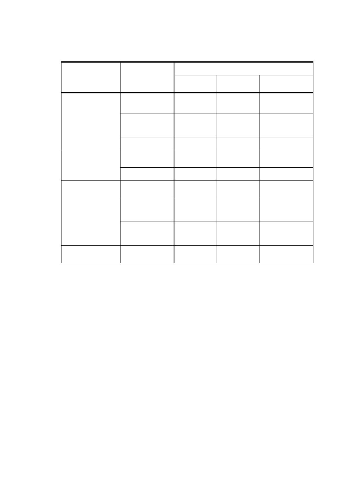
Table 149 - Overprinting behavior in the transparent imaging model
Affected colour
Value of blend function B (c
, c
) expressed as tint
b
s
Source color space
component of
group colour
OP false
OP true,
OP true,
space
OPM 0
OPM 1
DeviceCMYK,
C, M, Y, or K
cs
cs
cs if cs ≠ 0.0
specified directly,
cb if cs = 0.0
not in a sampled
image
Process colour
cs
cs
cs
component other
than CMYK
Spot colorant
cs (= 0.0)
cb
cb
Any process colour
Process colour
cs
cs
cs
space (including
component
other cases of
DeviceCMYK)
Spot colorant
cs (= 0.0)
cb
cb
Separation or
Process colour
cs (= 0.0)
cb
cb
DeviceN
component
Spot colorant
cs
cs
cs
named in source
space
Spot colorant not
cs (= 0.0)
cb
cb
named in source
space
A group (not an
All colour
cs
cs
cs
elementary object)
components
Colour component values are represented in these tables as subtractive tint values because overprinting is
typically applied to subtractive colorants such as inks rather than to additive ones such as phosphors on a
display screen. The CompatibleOverprint blend mode is therefore described as if it took subtractive arguments
and returned subtractive results. In reality, however, CompatibleOverprint (like all blend modes) shall treat
colour components as additive values; subtractive components shall be complemented before and after
application of the blend function.
NOTE 1
This note describes an important difference between Table 148 and Table 149. In Table 148, the process
colour components being discussed are the actual device colorants—the colour components of the output
device’s native colour space (DeviceGray, DeviceRGB, or DeviceCMYK). In Table 149, the process colour
components are those of the group’s colour space, which is not necessarily the same as that of the output
device (and can even be something like CalRGB or ICCBased). For this reason, the process colour
components of the group colour space cannot be treated as if they were spot colours in a Separation or
DeviceN colour space (see
“Spot Colours and Transparency”). This difference between opaque and
transparent overprinting and erasing rules arises only within a transparency group (including the page group, if
its colour space is different from the native colour space of the output device). There is no difference in the
treatment of spot colour components.
NOTE 2
Table 149 has one additional row at the bottom. It applies when painting an object that is a transparency group
rather than an elementary object (fill, stroke, text, image, or shading). As stated in 11.7.3, "Spot Colours and
Transparency," a group is considered to paint all colour components, both process and spot. Colour
components that were not explicitly painted by any object in the group have an additive colour value of 1.0
(subtractive tint 0.0). Since no information is retained about which components were actually painted within the
group, compatible overprinting is not possible in this case; the CompatibleOverprint blend mode reverts to
Normal, with no consideration of the overprint and overprint mode parameters. A transparency-aware
conforming writer can choose a more suitable blend mode, such as Darken, to produce an effect similar to
overprinting.
359
11.7.5
Rendering Parameters and Transparency
11.7.5.1
General
The opaque imaging model has several graphics state parameters dealing with the rendering of colour: the
current halftone
(see
“Halftone Dictionaries”), transfer functions
(“Transfer Functions”), rendering intent
(“Rendering Intents”), and black-generation and undercolor-removal functions (“Conversion from DeviceRGB
to DeviceCMYK”). All of these rendering parameters may be specified on a per-object basis; they control how a
particular object is rendered. When all objects are opaque, it is easy to define what this means. But when they
are transparent, more than one object may contribute to the colour at a given point; it is unclear which
rendering parameters to apply in an area where transparent objects overlap. At the same time, the transparent
imaging model should be consistent with the opaque model when only opaque objects are painted.
There are two categories of rendering parameters that are treated somewhat differently in the presence of
transparency. In the first category are halftone and transfer functions, which are applied only when the final
colour at a given point on the page is known. In the second category are rendering intent, black generation, and
undercolor removal, which are applied whenever colours are converted from one colour space to another.
11.7.5.2
Halftone and Transfer Function
When objects are transparent, rendering of an object does not occur when the object is specified but at some
later time. Hence, the implementation shall keep track of the halftone and transfer function parameters at each
point on the page from the time they are specified until the time rendering actually occurs. This means that
these rendering parameters shall be associated with regions of the page rather than with individual objects.
The halftone and transfer function to be used at any given point on the page shall be those in effect at the time
of painting the last (topmost) elementary graphics object enclosing that point, but only if the object is fully
opaque. Only elementary objects shall be relevant; the rendering parameters associated with a group object
are ignored. The topmost object at any point shall be defined to be the topmost elementary object in the entire
page stack that has a nonzero object shape value (fj ) at that point (that is, for which the point is inside the
object). An object shall be considered to be fully opaque if all of the following conditions hold at the time the
object is painted:
•
The current alpha constant in the graphics state (stroking or nonstroking, depending on the painting
operation) is 1.0.
•
The current blend mode in the graphics state is Normal (or Compatible, which is treated as equivalent to
Normal).
•
The current soft mask in the graphics state is None. If the object is an image XObject, there is not an
SMask entry in its image dictionary.
•
The foregoing three conditions were also true at the time the Do operator was invoked for the group
containing the object, as well as for any direct ancestor groups.
•
If the current colour is a tiling pattern, all objects in the definition of its pattern cell also satisfy the foregoing
conditions.
Together, these conditions ensure that only the object itself shall contribute to the colour at the given point,
completely obscuring the backdrop. For portions of the page whose topmost object is not fully opaque or that
are never painted at all, the default halftone and transfer function for the page shall be used.
If a graphics object is painted with overprinting enabled—that is, if the applicable (stroking or nonstroking)
overprint parameter in the graphics state is true—the halftone and transfer function to use at a given point shall
be determined independently for each colour component. Overprinting implicitly invokes the
CompatibleOverprint blend mode (see “Compatibility with Opaque Overprinting”). An object shall be considered
opaque for a given component only if CompatibleOverprint yields the source colour (not the backdrop colour)
for that component.
360
11.7.5.3
Rendering Intent and Colour Conversions
The rendering intent, black-generation, and undercolor-removal parameters control certain colour conversions.
In the presence of transparency, they may need to be applied earlier than the actual rendering of colour onto
the page.
The rendering intent influences the conversion from a CIE-based colour space to a target colour space, taking
into account the target space’s colour gamut (the range of colours it can reproduce). Whereas in the opaque
imaging model the target space shall always be the native colour space of the output device, in the transparent
model it may instead be the group colour space of a transparency group into which an object is being painted.
The rendering intent is needed at the moment such a conversion is performed—that is, when painting an
elementary or group object specified in a CIE-based colour space into a parent group having a different colour
space.
NOTE 1
This differs from the current halftone and transfer function, whose values are used only when all colour
compositing has been completed and rasterization is being performed.
In all cases, the rendering intent to use for converting an object’s colour (whether that of an elementary object
or of a transparency group) shall be determined by the rendering intent parameter associated with the object. In
particular:
•
When painting an elementary object with a CIE-based colour into a transparency group having a different
colour space, the rendering intent used shall be the current rendering intent in effect in the graphics state
at the time of the painting operation.
•
When painting a transparency group whose colour space is CIE-based into a parent group having a
different colour space, the rendering intent used shall be the current rendering intent in effect at the time
the Do operator is applied to the group.
•
When the colour space of the page group is CIE-based, the rendering intent used to convert colours to the
native colour space of the output device shall be the default rendering intent for the page.
NOTE 2
Since there may be one or more nested transparency groups having different CIE-based colour spaces, the
colour of an elementary source object may be converted to the device colour space in multiple stages,
controlled by the rendering intent in effect at each stage. The proper choice of rendering intent at each stage
depends on the relative gamuts of the source and target colour spaces. It is specified explicitly by the
document producer, not prescribed by the PDF specification, since no single policy for managing rendering
intents is appropriate for all situations.
A similar approach works for the black-generation and undercolor-removal functions, which shall be applied
only during conversion from DeviceRGB to DeviceCMYK colour spaces:
•
When painting an elementary object with a DeviceRGB colour directly into a transparency group whose
colour space is DeviceCMYK, the functions used shall be the current black-generation and undercolor-
removal functions in effect in the graphics state at the time of the painting operation.
•
When painting a transparency group whose colour space is DeviceRGB into a parent group whose colour
space is DeviceCMYK, the functions used shall be the ones in effect at the time the Do operator is applied
to the group.
•
When the colour space of the page group is DeviceRGB and the native colour space of the output device
is DeviceCMYK, the functions used to convert colours to the device’s colour space shall be the default
functions for the page.
361

12
Interactive Features
12.1
General
For purposes of the trigger events E (enter), X (exit), D (down), and U (up), the term mouse denotes a generic
pointing device with the following characteristics:
•
A selection button that can be pressed, held down, and released. If there is more than one mouse button,
the selection button is typically the left button.
•
A notion of location—that is, an indication of where on the screen the device is pointing. Location is
typically denoted by a screen cursor.
•
A notion of focus—that is, which element in the document is currently interacting with the with the user. In
many systems, this element is denoted by a blinking caret, a focus rectangle, or a colour change.
This clause describes the PDF features that allow a user to interact with a document on the screen, using the
mouse and keyboard (with the exception of multimedia features, which are described in 13, “Multimedia
Features”):
•
Preference settings to control the way the document is presented on the screen
(12.2,
“Viewer
Preferences”)
•
Navigation facilities for moving through the document in a variety of ways (Sections 12.3, “Document-Level
Navigation” and 12.4, “Page-Level Navigation”)
•
Annotations for adding text notes, sounds, movies, and other ancillary information to the document (12.5,
“Annotations”)
•
Actions that can be triggered by specified events (12.6, “Actions”)
•
Interactive forms for gathering information from the user (12.7, “Interactive Forms”)
•
Digital signatures that authenticate the identity of a user and the validity of the document’s contents (12.8,
“Digital Signatures”)
•
Measurement properties that enable the display of real-world units corresponding to objects on a page
(12.9, “Measurement Properties”)
12.2
Viewer Preferences
The ViewerPreferences entry in a document’s catalogue (see 7.7.2, “Document Catalog”) designates a viewer
preferences dictionary (PDF 1.2) controlling the way the document shall be presented on the screen or in print.
If no such dictionary is specified, conforming readers should behave in accordance with their own current user
preference settings. Table 150 shows the contents of the viewer preferences dictionary.
Table 150 - Entries in a viewer preferences dictionary
Key
Type
Value
HideToolbar
boolean
(Optional) A flag specifying whether to hide the conforming
reader’s tool bars when the document is active. Default value:
false.
HideMenubar
boolean
(Optional) A flag specifying whether to hide the conforming
reader’s menu bar when the document is active. Default value:
false.
362

Table 150 - Entries in a viewer preferences dictionary (continued)
Key
Type
Value
HideWindowUI
boolean
(Optional) A flag specifying whether to hide user interface
elements in the document’s window (such as scroll bars and
navigation controls), leaving only the document’s contents
displayed. Default value: false.
FitWindow
boolean
(Optional) A flag specifying whether to resize the document’s
window to fit the size of the first displayed page. Default value:
false.
CenterWindow
boolean
(Optional) A flag specifying whether to position the document’s
window in the center of the screen. Default value: false.
DisplayDocTitle
boolean
(Optional; PDF 1.4) A flag specifying whether the window’s title
bar should display the document title taken from the Title entry of
the document information dictionary
(see
14.3.3,
“Document
Information Dictionary”). If false, the title bar should instead
display the name of the PDF file containing the document. Default
value: false.
NonFullScreenPageMode
name
(Optional) The document’s page mode, specifying how to display
the document on exiting full-screen mode:
UseNone
Neither document outline nor thumbnail images
visible
UseOutlines Document outline visible
UseThumbs Thumbnail images visible
UseOC
Optional content group panel visible
This entry is meaningful only if the value of the PageMode entry
in the Catalog dictionary
(see 7.7.2,
“Document Catalog”) is
FullScreen; it shall be ignored otherwise. Default value: UseNone.
Direction
name
(Optional; PDF 1.3) The predominant reading order for text:
L2R Left to right
R2L Right to left (including vertical writing systems, such as
Chinese, Japanese, and Korean)
This entry has no direct effect on the document’s contents or page
numbering but may be used to determine the relative positioning
of pages when displayed side by side or printed n-up. Default
value: L2R.
ViewArea
name
(Optional; PDF 1.4) The name of the page boundary representing
the area of a page that shall be displayed when viewing the
document on the screen. The value is the key designating the
relevant page boundary in the page object (see 7.7.3, “Page Tree”
and 14.11.2, “Page Boundaries”). If the specified page boundary
is not defined in the page object, its default value shall be used,
as specified in Table 30. Default value: CropBox.
This entry is intended primarily for use by prepress applications
that interpret or manipulate the page boundaries as described in
14.11.2, “Page Boundaries.”
NOTE 1
Most conforming readers disregard it.
363

Table 150 - Entries in a viewer preferences dictionary (continued)
Key
Type
Value
ViewClip
name
(Optional; PDF 1.4) The name of the page boundary to which the
contents of a page shall be clipped when viewing the document
on the screen. The value is the key designating the relevant page
boundary in the page object (see 7.7.3, “Page Tree” and 14.11.2,
“Page Boundaries”). If the specified page boundary is not defined
in the page object, its default value shall be used, as specified in
Table 30. Default value: CropBox.
This entry is intended primarily for use by prepress applications
that interpret or manipulate the page boundaries as described in
14.11.2, “Page Boundaries.”
NOTE 2
Most conforming readers disregard it.
PrintArea
name
(Optional; PDF 1.4) The name of the page boundary representing
the area of a page that shall be rendered when printing the
document. The value is the key designating the relevant page
boundary in the page object (see 7.7.3, “Page Tree” and 14.11.2,
“Page Boundaries”). If the specified page boundary is not defined
in the page object, its default value shall be used, as specified in
Table 30. Default value: CropBox.
This entry is intended primarily for use by prepress applications
that interpret or manipulate the page boundaries as described in
14.11.2, “Page Boundaries.”
NOTE 3
Most conforming readers disregard it.
PrintClip
name
(Optional; PDF 1.4) The name of the page boundary to which the
contents of a page shall be clipped when printing the document.
The value is the key designating the relevant page boundary in
the page object (see 7.7.3,
“Page Tree” and 14.11.2, “Page
Boundaries”). If the specified page boundary is not defined in the
page object, its default value shall be used, as specified in
Table 30. Default value: CropBox.
This entry is intended primarily for use by prepress applications
that interpret or manipulate the page boundaries as described in
14.11.2, “Page Boundaries.”
NOTE 4
Most conforming readers disregard it.
PrintScaling
name
(Optional; PDF 1.6) The page scaling option that shall be selected
when a print dialog is displayed for this document. Valid values
are None, which indicates no page scaling, and AppDefault, which
indicates the conforming reader’s default print scaling. If this entry
has an unrecognized value, AppDefault shall be used. Default
value: AppDefault.
If the print dialog is suppressed and its parameters are provided
from some other source, this entry nevertheless shall be honored.
Duplex
name
(Optional; PDF 1.7) The paper handling option that shall be used
when printing the file from the print dialog. The following values
are valid:
Simplex
Print single-sided
DuplexFlipShortEdge Duplex and flip on the short edge of the
sheet
DuplexFlipLongEdge Duplex and flip on the long edge of the
sheet
Default value: none
364

Table 150 - Entries in a viewer preferences dictionary (continued)
Key
Type
Value
PickTrayByPDFSize
boolean
(Optional; PDF 1.7) A flag specifying whether the PDF page size
shall be used to select the input paper tray. This setting influences
only the preset values used to populate the print dialog presented
by a conforming reader. If PickTrayByPDFSize is true, the check
box in the print dialog associated with input paper tray shall be
checked.
This setting has no effect on operating systems that do not
provide the ability to pick the input tray by size.
Default value: as defined by the conforming reader
PrintPageRange
array
(Optional; PDF 1.7) The page numbers used to initialize the print
dialog box when the file is printed. The array shall contain an even
number of integers to be interpreted in pairs, with each pair
specifying the first and last pages in a sub-range of pages to be
printed.The first page of the PDF file shall be denoted by 1.
Default value: as defined by the conforming reader
NumCopies
integer
(Optional; PDF 1.7) The number of copies that shall be printed
when the print dialog is opened for this file. Values outside this
range shall be ignored.
Default value: as defined by the conforming reader, but typically 1
12.3
Document-Level Navigation
12.3.1
General
The features described in this sub-clause allow a conforming reader to present the user with an interactive,
global overview of a document in either of two forms:
•
As a hierarchical outline showing the document’s internal structure
•
As a collection of thumbnail images representing the pages of the document in miniature form
Each item in the outline or each thumbnail image may be associated with a corresponding destination in the
document, so that the user can jump directly to the destination by clicking with the mouse.
12.3.2
Destinations
12.3.2.1
General
A destination defines a particular view of a document, consisting of the following items:
•
The page of the document that shall be displayed
•
The location of the document window on that page
•
The magnification (zoom) factor
Destinations may be associated with outline items (see 12.3.3, “Document Outline”), annotations (12.5.6.5,
“Link Annotations”), or actions (12.6.4.2, “Go-To Actions” and 12.6.4.3, “Remote Go-To Actions”). In each case,
the destination specifies the view of the document that shall be presented when the outline item or annotation
is opened or the action is performed. In addition, the optional OpenAction entry in a document’s catalogue
(7.7.2, “Document Catalog”) may specify a destination that shall be displayed when the document is opened. A
destination may be specified either explicitly by an array of parameters defining its properties or indirectly by
name.
365

12.3.2.2
Explicit Destinations
Table 151 shows the allowed syntactic forms for specifying a destination explicitly in a PDF file. In each case,
page is an indirect reference to a page object (except in a remote go-to action; see 12.6.4.3, “Remote Go-To
Actions”). All coordinate values (left, right, top, and bottom) shall be expressed in the default user space
coordinate system. The page’s bounding box is the smallest rectangle enclosing all of its contents. (If any side
of the bounding box lies outside the page’s crop box, the corresponding side of the crop box shall be used
instead; see 14.11.2, “Page Boundaries,” for further discussion of the crop box.)
No page object can be specified for a destination associated with a remote go-to action (see 12.6.4.3, “Remote
Go-To Actions”) because the destination page is in a different PDF document. In this case, the page parameter
specifies an integer page number
within the remote document instead of a page object in the current
document.
Table 151 - Destination syntax
Syntax
Meaning
[page
/XYZ left top zoom ]
Display the page designated by page, with the coordinates (left, top)
positioned at the upper-left corner of the window and the contents of
the page magnified by the factor zoom. A null value for any of the
parameters left, top, or zoom specifies that the current value of that
parameter shall be retained unchanged. A zoom value of 0 has the
same meaning as a null value.
[page
/Fit ]
Display the page designated by page, with its contents magnified just
enough to fit the entire page within the window both horizontally and
vertically. If the required horizontal and vertical magnification factors
are different, use the smaller of the two, centering the page within the
window in the other dimension.
[page
/FitH top ]
Display the page designated by page, with the vertical coordinate top
positioned at the top edge of the window and the contents of the page
magnified just enough to fit the entire width of the page within the
window. A null value for top specifies that the current value of that
parameter shall be retained unchanged.
[page
/FitV left ]
Display the page designated by page, with the horizontal coordinate
left positioned at the left edge of the window and the contents of the
page magnified just enough to fit the entire height of the page within
the window. A null value for left specifies that the current value of that
parameter shall be retained unchanged.
[page
/FitR left bottom right top ]
Display the page designated by page, with its contents magnified just
enough to fit the rectangle specified by the coordinates left, bottom,
right, and top entirely within the window both horizontally and vertically.
If the required horizontal and vertical magnification factors are
different, use the smaller of the two, centering the rectangle within the
window in the other dimension.
[page
/FitB ]
(PDF 1.1) Display the page designated by page, with its contents
magnified just enough to fit its bounding box entirely within the window
both horizontally and vertically. If the required horizontal and vertical
magnification factors are different, use the smaller of the two,
centering the bounding box within the window in the other dimension.
[page
/FitBH top ]
(PDF 1.1) Display the page designated by page, with the vertical
coordinate top positioned at the top edge of the window and the
contents of the page magnified just enough to fit the entire width of its
bounding box within the window. A null value for top specifies that the
current value of that parameter shall be retained unchanged.
366

Table 151 - Destination syntax (continued)
Syntax
Meaning
[page
/FitBV left ]
(PDF 1.1) Display the page designated by page, with the horizontal
coordinate left positioned at the left edge of the window and the
contents of the page magnified just enough to fit the entire height of its
bounding box within the window. A null value for left specifies that the
current value of that parameter shall be retained unchanged.
12.3.2.3
Named Destinations
Instead of being defined directly with the explicit syntax shown in Table 151, a destination may be referred to
indirectly by means of a name object (PDF 1.1) or a byte string (PDF 1.2). This capability is especially useful
when the destination is located in another PDF document.
NOTE 1
A link to the beginning of Chapter 6 in another document might refer to the destination by a name, such as
Chap6 . begin, instead of by an explicit page number in the other document. Then, the location of the chapter in
the other document could change without invalidating the link. If an annotation or outline item that refers to a
named destination has an associated action, such as a remote go-to action (see 12.6.4.3, “Remote Go-To
Actions”) or a thread action (12.6.4.6, “Thread Actions”), the destination is in the file specified by the action’s F
entry, if any; if there is no F entry, the destination is in the current file.
In PDF 1.1, the correspondence between name objects and destinations shall be defined by the Dests entry in
the document catalogue (see 7.7.2, “Document Catalog”). The value of this entry shall be a dictionary in which
each key is a destination name and the corresponding value is either an array defining the destination, using
the syntax shown in Table 151, or a dictionary with a D entry whose value is such an array.
NOTE 2
The latter form allows additional attributes to be associated with the destination, as well as enabling a go-to
action (see 12.6.4.2, “Go-To Actions”) that shall be used as the target of a named destination.
In PDF 1.2 and later, the correspondence between strings and destinations may alternatively be defined by the
Dests entry in the document’s name dictionary (see 7.7.4, “Name Dictionary”). The value of this entry shall be
a name tree (7.9.6, “Name Trees”) mapping name strings to destinations. (The keys in the name tree may be
treated as text strings for display purposes.) The destination value associated with a key in the name tree may
be either an array or a dictionary, as described in the preceding paragraph.
NOTE 3
The use of strings as destination names is a PDF 1.2 feature. If compatibility with earlier versions of PDF is
required, only name objects may be used to refer to named destinations. A document that supports PDF 1.2
can contain both types. However, if backward compatibility is not a consideration, applications should use the
string form of representation in the Dests name tree.
12.3.3
Document Outline
A PDF document may contain a document outline that the conforming reader may display on the screen,
allowing the user to navigate interactively from one part of the document to another. The outline consists of a
tree-structured hierarchy of outline items (sometimes called bookmarks), which serve as a visual table of
contents to display the document’s structure to the user. The user may interactively open and close individual
items by clicking them with the mouse. When an item is open, its immediate children in the hierarchy shall
become visible on the screen; each child may in turn be open or closed, selectively revealing or hiding further
parts of the hierarchy. When an item is closed, all of its descendants in the hierarchy shall be hidden. Clicking
the text of any visible item activates the item, causing the conforming reader to jump to a destination or trigger
an action associated with the item.
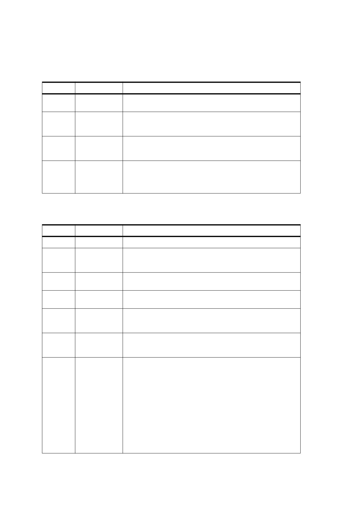
The root of a document’s outline hierarchy is an outline dictionary specified by the Outlines entry in the
document catalogue (see 7.7.2, “Document Catalog”). Table 152 shows the contents of this dictionary. Each
individual outline item within the hierarchy shall be defined by an outline item dictionary (Table 153). The items
at each level of the hierarchy form a linked list, chained together through their Prev and Next entries and
accessed through the First and Last entries in the parent item (or in the outline dictionary in the case of top-
367
level items). When displayed on the screen, the items at a given level shall appear in the order in which they
occur in the linked list.
Table 152 - Entries in the outline dictionary
Key
Type
Value
Type
name
(Optional) The type of PDF object that this dictionary describes; if
present, shall be Outlines for an outline dictionary.
First
dictionary
(Required if there are any open or closed outline entries; shall be an
indirect reference) An outline item dictionary representing the first top-
level item in the outline.
Last
dictionary
(Required if there are any open or closed outline entries; shall be an
indirect reference) An outline item dictionary representing the last top-
level item in the outline.
Count
integer
(Required if the document has any open outline entries) Total number
of visible outline items at all levels of the outline. The value cannot be
negative.
This entry shall be omitted if there are no open outline items.
Table 153 - Entries in an outline item dictionary
Key
Type
Value
Title
text string
(Required) The text that shall be displayed on the screen for this item.
Parent
dictionary
(Required; shall be an indirect reference) The parent of this item in the
outline hierarchy. The parent of a top-level item shall be the outline
dictionary itself.
Prev
dictionary
(Required for all but the first item at each level; shall be an indirect
reference) The previous item at this outline level.
Next
dictionary
(Required for all but the last item at each level; shall be an indirect
reference) The next item at this outline level.
First
dictionary
(Required if the item has any descendants; shall be an indirect
reference) The first of this item’s immediate children in the outline
hierarchy.
Last
dictionary
(Required if the item has any descendants; shall be an indirect
reference) The last of this item’s immediate children in the outline
hierarchy.
Count
integer
(Required if the item has any descendants) If the outline item is open,
Count is the sum of the number of visible descendent outline items at
all levels. The number of visible descendent outline items shall be
determined by the following recursive process:
Step 1. Initialize Count to zero.
Step 2. Add to Count the number of immediate children. During
repetitions of this step, update only the Count of the original
outline item.
Step 3. For each of those immediate children whose Count is
positive and non-zero, repeat steps 2 and 3.
If the outline item is closed, Count is negative and its absolute value is
the number of descendants that would be visible if the outline item
were opened.
368
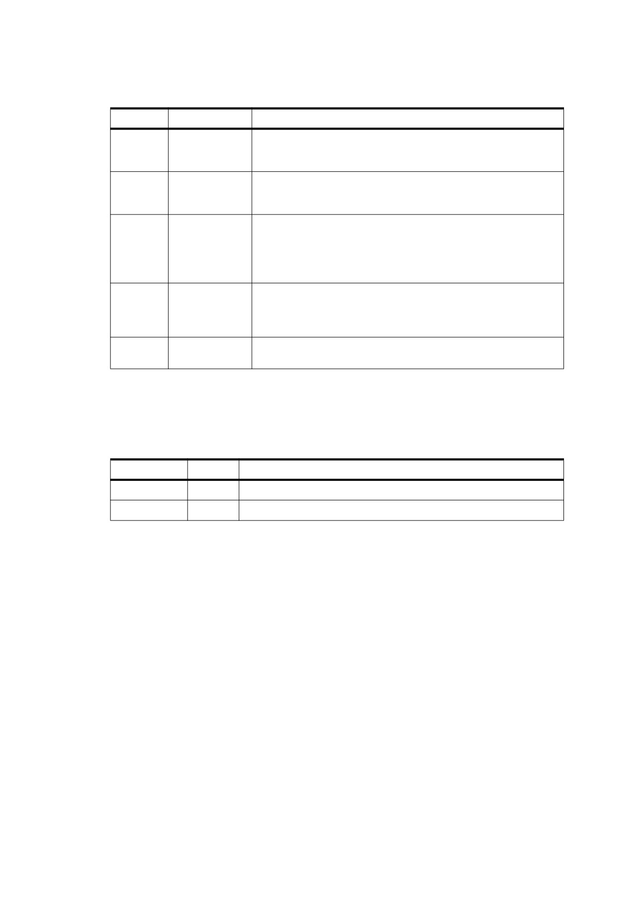
Table 153 - Entries in an outline item dictionary (continued)
Key
Type
Value
Dest
name,
(Optional; shall not be present if an A entry is present) The destination
byte string, or
that shall be displayed when this item is activated
(see
12.3.2,
array
“Destinations”).
A
dictionary
(Optional; PDF 1.1; shall not be present if a Dest entry is present) The
action that shall be performed when this item is activated (see 12.6,
“Actions”).
SE
dictionary
(Optional; PDF 1.3; shall be an indirect reference) The structure
element to which the item refers (see 14.7.2, “Structure Hierarchy”).
(PDF 1.0) An item may also specify a destination
(Dest)
corresponding to an area of a page where the contents of the
designated structure element are displayed.
C
array
(Optional; PDF 1.4) An array of three numbers in the range 0.0 to 1.0,
representing the components in the DeviceRGB colour space of the
colour that shall be used for the outline entry’s text. Default value:
[0.0
0.0 0.0 ].
F
integer
(Optional; PDF 1.4) A set of flags specifying style characteristics for
displaying the outline item’s text (see Table 154). Default value: 0.
The value of the outline item dictionary’s F entry (PDF 1.4) shall be an integer interpreted as one-bit flags
specifying style characteristics for displaying the item. Bit positions within the flag word are numbered from low-
order to high-order bits, with the lowest-order bit numbered 1. Table 154 shows the meanings of the flags; all
other bits of the integer shall be 0.
Table 154 - Outline item flags
Bit position
Name
Meaning
1
Italic
If set to 1, display the item in italic.
2
Bold
If set to 1, display the item in bold.
EXAMPLE
The following example shows a typical outline dictionary and outline item dictionary. See H.6, “Outline
Hierarchy Example” for an example of a complete outline hierarchy.
21 0 obj
<<
/Count 6
/First
22 0 R
/Last
29 0 R
>>
endobj
22 0 obj
<<
/Title
( Chapter 1 )
/Parent 21 0 R
/Next 26 0 R
/First
23 0 R
/Last
25 0 R
/Count 3
/Dest [ 3 0 R /XYZ 0 792 0 ]
>>
endobj
369
12.3.4
Thumbnail Images
A PDF document may contain thumbnail images representing the contents of its pages in miniature form. A
conforming reader may display these images on the screen, allowing the user to navigate to a page by clicking
its thumbnail image:
NOTE
Thumbnail images are not required, and may be included for some pages and not for others.
The thumbnail image for a page shall be an image XObject specified by the Thumb entry in the page object
(see 7.7.3, “Page Tree”). It has the usual structure for an image dictionary (8.9.5, “Image Dictionaries”), but
only the Width, Height, ColorSpace, BitsPerComponent, and Decode entries are significant; all of the other
entries listed in Table 89 shall be ignored if present. (If a Subtype entry is specified, its value shall be Image.)
The image’s colour space shall be either DeviceGray or DeviceRGB, or an Indexed space based on one of
these.
EXAMPLE
This example shows a typical thumbnail image definition.
12 0 obj
<<
/Width 76
/Height 99
/ColorSpace /DeviceRGB
/BitsPerComponent 8
/Length 13 0 R
/Filter
[ /ASCII85Decode /DCTDecode ]
>>
stream
s4IA>!"M;*Ddm8XA,lT0!!3,S!/(=R!<E3%!<N<(!WrK*!WrN,
… Omitted data…
endstream
endobj
13 0 obj
% Length of stream
…
endobj
12.3.5
Collections
Beginning with PDF 1.7, PDF documents may specify how a conforming reader’s user interface presents
collections of file attachments, where the attachments are related in structure or content. Such a presentation is
called a portable collection.
NOTE 1
The intent of portable collections is to present, sort, and search collections of related documents embedded in
the containing PDF document, such as email archives, photo collections, and engineering bid sets. There is no
requirement that documents in a collection have an implicit relationship or even a similarity; however, showing
differentiating characteristics of related documents can be helpful for document navigation.
A collection dictionary specifies the viewing and organizational characteristics of portable collections. If this
dictionary is present in a PDF document, the conforming reader shall present the document as a portable
collection. The EmbeddedFiles name tree specifies file attachments (see 7.11.4, “Embedded File Streams”).
When a conforming reader first opens a PDF document containing a collection, it shall display the contents of
the initial document, along with a list of the documents present in the EmbeddedFiles name tree. The
document list shall include the additional document information specified by the collection schema. The initial
document may be the container PDF or one of the embedded documents.
NOTE 2
The page content in the initial document should contain information that helps the user understand what is
contained in the collection, such as a title and an introductory paragraph.
The file attachments comprising a collection shall be located in the EmbeddedFiles name tree. All attachments
in that tree are in the collection; any attachments not in that tree are not.
370
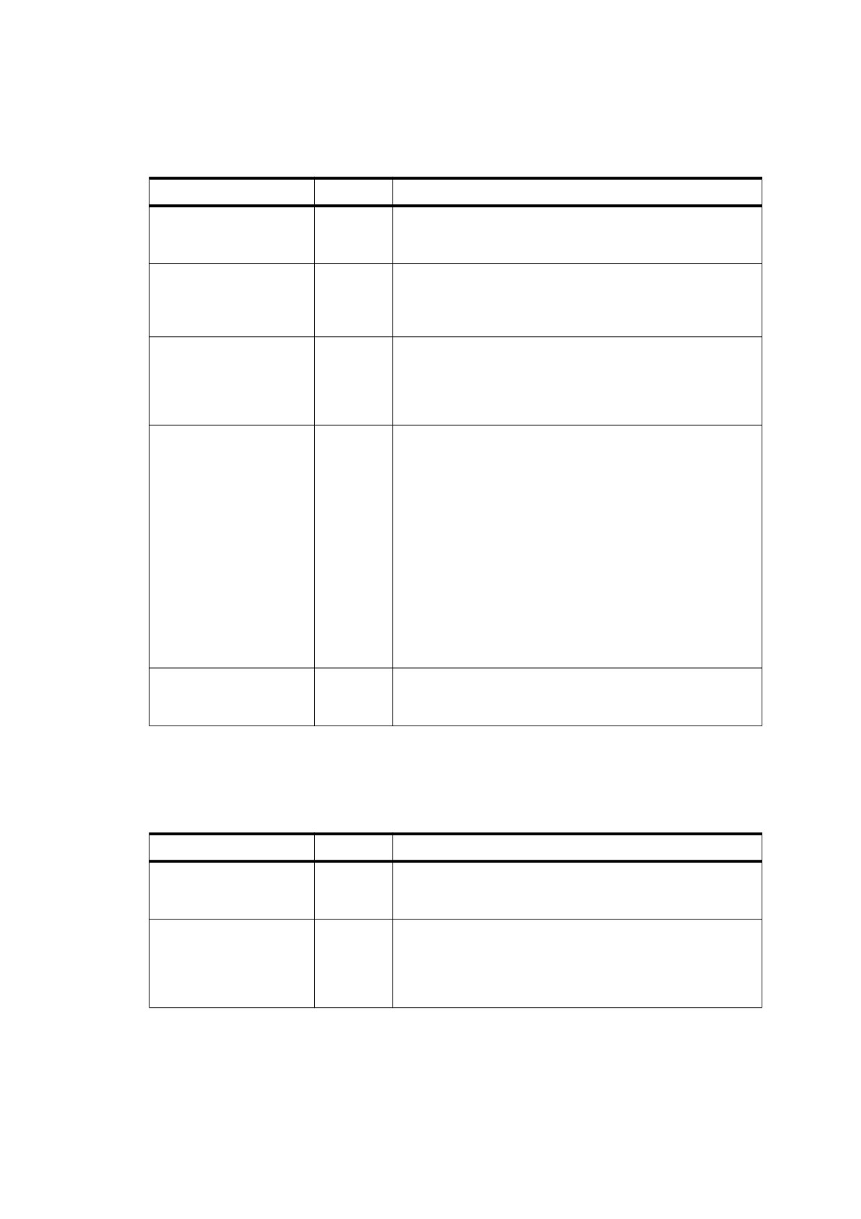
Table 155 describes the entries in a collection dictionary.
Table 155 - Entries in a collection dictionary
Key
Type
Value
Type
name
(Optional) The type of PDF object that this dictionary
describes; if present, shall be Collection for a collection
dictionary.
Schema
dictionary
(Optional) A collection schema dictionary (see Table 156). If
absent, the conforming reader may choose useful defaults
that are known to exist in a file specification dictionary, such
as the file name, file size, and modified date.
D
byte string
(Optional) A string that identifies an entry in the
EmbeddedFiles name tree, determining the document that
shall be initially presented in the user interface. If the D entry
is missing or in error, the initial document shall be the one
that contains the collection dictionary.
View
name
(Optional) The initial view. The following values are valid:
D The collection view shall be presented in details mode,
with all information in the Schema dictionary presented
in a multi-column format. This mode provides the most
information to the user.
T The collection view shall be presented in tile mode, with
each file in the collection denoted by a small icon and a
subset of information from the Schema dictionary. This
mode provides top-level information about the file
attachments to the user.
H The collection view shall be initially hidden, The
conforming reader shall provide means for the user to
view the collection by some explicit action.
Default value: D
Sort
dictionary
(Optional) A collection sort dictionary, which specifies the
order in which items in the collection shall be sorted in the
user interface (see Table 158).
A collection schema dictionary consists of a variable number of individual collection field dictionaries. Each
collection field dictionary has a key chosen by the conforming writer, which shall be used to associate a field
with data in a file specification. Table 156 describes the entries in a collection schema dictionary.
Table 156 - Entries in a collection schema dictionary
Key
Type
Value
Type
name
(Optional) The type of PDF object that this dictionary
describes; if present, shall be CollectionSchema for a
collection schema dictionary.
Other keys
dictionary
(Optional) A collection field dictionary. Each key name is
chosen at the discretion of the conforming writer. The key
name shall be used to identify a corresponding collection
item dictionary referenced from the file specification
dictionary's CI entry (see CI key in Table 44).
371

A collection field dictionary describes the attributes of a particular field in a portable collection, including the
type of data stored in the field and the lookup key used to locate the field data in the file specification dictionary.
Table 157 describes the entries in a collection field dictionary.
Table 157 - Entries in a collection field dictionary
Key
Type
Value
Type
name
(Optional) The type of PDF object that this dictionary describes; if
present, shall be CollectionField for a collection field dictionary.
Subtype
name
(Required) The subtype of collection field or file-related field that this
dictionary describes. This entry identifies the type of data that shall
be stored in the field.
The following values identify the types of fields in the collection item
or collection subitem dictionary:
S A text field. The field data shall be stored as a PDF text string.
D A date field. The field data shall be stored as a PDF date
string.
N A number field. The field data shall be stored as a PDF
number.
The following values identify the types of file-related fields:
F
The field data shall be the file name of the
embedded file stream, as identified by the UF entry
of the file specification, if present; otherwise by the F
entry of the file specification (see Table 44).
Desc
The field data shall be the description of the
embedded file stream, as identified by the Desc
entry in the file specification dictionary
(see
Table 44).
ModDate
The field data shall be the modification date of the
embedded file stream, as identified by the ModDate
entry in the embedded file parameter dictionary (see
Table 46).
CreationDate The field data shall be the creation date of the
embedded file stream, as identified by the
CreationDate entry in the embedded file parameter
dictionary (see Table 46).
Size
The field data shall be the size of the embedded file,
as identified by the Size entry in the embedded file
parameter dictionary (see Table 46).
N
text string
(Required) The textual field name that shall be presented to the user
by the conforming reader.
O
integer
(Optional) The relative order of the field name in the user interface.
Fields shall be sorted by the conforming reader in ascending order.
V
boolean
(Optional) The initial visibility of the field in the user interface.
Default value: true.
E
boolean
(Optional) A flag indicating whether the conforming reader should
provide support for editing the field value. Default value: false.
A collection sort dictionary identifies the fields that shall be used to sort items in the collection. The type of
sorting depends on the type of data:
•
Text strings shall be ordered lexically from smaller to larger, if ascending order is specified.
NOTE 3
Lexical ordering is an implementation dependency for conforming readers.
372

•
Numbers shall be ordered numerically from smaller to larger, if ascending order is specified.
•
Dates shall be ordered from oldest to newest, if ascending order is specified.
Table 158 describes the entries in a collection sort dictionary.
Table 158 - Entries in a collection sort dictionary
Key
Type
Value
Type
name
(Optional) The type of PDF object that this dictionary describes; if
present, shall be CollectionSort for a collection sort dictionary.
S
name or
(Required) The name or names of fields that the conforming reader
array
shall use to sort the items in the collection. If the value is a name, it
identifies a field described in the parent collection dictionary.
If the value is an array, each element of the array shall be a name that
identifies a field described in the parent collection dictionary. The
array form shall be used to allow additional fields to contribute to the
sort, where each additional field shall be used to break ties. More
specifically, if multiple collection item dictionaries have the same
value for the first field named in the array, the values for successive
fields named in the array shall be used for sorting, until a unique order
is determined or until the named fields are exhausted.
A
boolean
(Optional) If the value is a boolean, it specifies whether the
or array
conforming reader shall sort the items in the collection in ascending
order (true) or descending order (false). If the value is an array, each
element of the array shall be a boolean value that specifies whether
the entry at the same index in the S array shall be sorted in ascending
or descending order.
If the number of entries in the A array is larger than the number of
entries in the S array the extra entries in the A array shall be ignored.
If the number of entries in the A array is less than the number of
entries in the S array the missing entries in the A array shall be
assumed to be true.
Default value: true.
EXAMPLE 1
This example shows a collection dictionary representing an email in-box, where each item in the
collection is an email message. The actual email messages are contained in file specification dictionaries.
The organizational data associated with each email is described in a collection schema dictionary. Most
actual organizational data (from, to, date, and subject) is provided in a collection item dictionary, but the
size data comes from the embedded file parameter dictionary.
/Collection <<
/Type /Collection
/Schema <<
/Type /CollectionSchema
/from << /Subtype /S /N (From) /O 1 /V true /E false>>
/to << /Subtype /S /N (To) /O 2 /V true /E false >>
/date << /Subtype /D /N (Date received) /O 3 /V true /E false >>
/subject << /Subtype /S /N (Subject) /O 4 /V true /E false >>
/size << /Subtype /Size /N (Size) /O 5 /V true /E false >>
>>
/D (Doc1)
/View /D
/Sort << /S /date /A false >>
>>
373
EXAMPLE 2
This example shows a collection item dictionary and a collection subitem dictionary. These dictionaries
contain entries that correspond to the schema entries specified in the Example in 12.4.2, “Page Labels.”.
7.11.6, “Collection Items” specifies the collection item and collection subitem dictionaries.
/CI <<
/Type /CollectionItem
/from (Rob McAfee)
/to (Patty McAfee)
/subject <<
/Type /CollectionSubitem
/P (Re:)
/D (Let's have lunch on Friday!)
>>
/date (D:20050621094703-07’00’)
>>
12.4
Page-Level Navigation
12.4.1
General
This sub-clause describes PDF facilities that enable the user to navigate from page to page within a document:
•
Page labels for numbering or otherwise identifying individual pages (see 12.4.2, “Page Labels”).
•
Article threads, which chain together items of content within the document that are logically connected but
not physically sequential (see 12.4.3, “Articles”).
•
Presentations that display the document in the form of a slide show, advancing from one page to the next
either automatically or under user control (see 12.4.4, “Presentations”).
For another important form of page-level navigation, see 12.5.6.5, “Link Annotations.”
12.4.2
Page Labels
Each page in a PDF document shall be identified by an integer page index that expresses the page’s relative
position within the document. In addition, a document may optionally define page labels (PDF 1.3) to identify
each page visually on the screen or in print. Page labels and page indices need not coincide: the indices shall
be fixed, running consecutively through the document starting from 0 for the first page, but the labels may be
specified in any way that is appropriate for the particular document.
NOTE 1
If the document begins with 12 pages of front matter numbered in roman numerals and the remainder of the
document is numbered in arabic, the first page would have a page index of 0 and a page label of i, the twelfth
page would have index 11 and label xii, and the thirteenth page would have index 12 and label 1.
For purposes of page labelling, a document shall be divided into labelling ranges, each of which is a series of
consecutive pages using the same numbering system. Pages within a range shall be numbered sequentially in
ascending order. A page’s label consists of a numeric portion based on its position within its labelling range,
optionally preceded by a label prefix denoting the range itself.
NOTE 2
The pages in an appendix might be labeled with decimal numeric portions prefixed with the string A-; the
resulting page labels would be A-1, A-2, and so on.
A document’s labelling ranges shall be defined by the PageLabels entry in the document catalogue (see 7.7.2,
“Document Catalog”). The value of this entry shall be a number tree (7.9.7, “Number Trees”), each of whose
keys is the page index of the first page in a labelling range. The corresponding value shall be a page label
dictionary defining the labelling characteristics for the pages in that range. The tree shall include a value for
page index 0. Table 159 shows the contents of a page label dictionary.
374
Table 159 - Entries in a page label dictionary
Key
Type
Value
Type
name
(Optional) The type of PDF object that this dictionary describes; if present, shall be
PageLabel for a page label dictionary.
S
name
(Optional) The numbering style that shall be used for the numeric portion of each
page label:
D Decimal arabic numerals
R Uppercase roman numerals
r
Lowercase roman numerals
A Uppercase letters (A to Z for the first 26 pages, AA to ZZ for the next 26, and
so on)
a Lowercase letters (a to z for the first 26 pages, aa to zz for the next 26, and so
on)
There is no default numbering style; if no S entry is present, page labels shall
consist solely of a label prefix with no numeric portion.
NOTE
If the P entry (next) specifies the label prefix Contents, each page is
simply labeled Contents with no page number. (If the P entry is also missing or
empty, the page label is an empty string.)
P
text string
(Optional) The label prefix for page labels in this range.
St
integer
(Optional) The value of the numeric portion for the first page label in the range.
Subsequent pages shall be numbered sequentially from this value, which shall be
greater than or equal to 1. Default value: 1.
EXAMPLE
The following example shows a document with pages labeled
i, ii, iii, iv, 1, 2, 3, A-8, A-9, …
1 0 obj
<< /Type /Catalog
/PageLabels
<< /Nums [
0 <<
/S /r
>>
% A number tree containing
4 <<
/S /D >>
% three page label dictionaries
7 <<
/S /D
/P ( A- )
/St
8
>>
]
>>
…
>>
endobj
12.4.3
Articles
Some types of documents may contain sequences of content items that are logically connected but not
physically sequential.
EXAMPLE 1
A news story may begin on the first page of a newsletter and run over onto one or more nonconsecutive
interior pages.
To represent such sequences of physically discontiguous but logically related items, a PDF document may
define one or more articles (PDF 1.1). The sequential flow of an article shall be defined by an article thread; the
individual content items that make up the article are called beads on the thread. Conforming readers may
provide navigation facilities to allow the user to follow a thread from one bead to the next.
The optional Threads entry in the document catalogue (see 7.7.2, “Document Catalog”) holds an array of
thread dictionaries (Table 160) defining the document’s articles. Each individual bead within a thread shall be
375
represented by a bead dictionary (Table 161). The thread dictionary’s F entry shall refer to the first bead in the
thread; the beads shall be chained together sequentially in a doubly linked list through their N (next) and V
(previous) entries. In addition, for each page on which article beads appear, the page object (see 7.7.3, “Page
Tree”) shall contain a B entry whose value is an array of indirect references to the beads on the page, in
drawing order.
Table 160 - Entries in a thread dictionary
Key
Type
Value
Type
name
(Optional) The type of PDF object that this dictionary describes; if present,
shall be Thread for a thread dictionary.
F
dictionary
(Required; shall be an indirect reference) The first bead in the thread.
I
dictionary
(Optional) A thread information dictionary containing information about the
thread, such as its title, author, and creation date. The contents of this
dictionary shall conform to the syntax for the document information dictionary
(see 14.3.3, “Document Information Dictionary”).
Table 161 - Entries in a bead dictionary
Key
Type
Value
Type
name
(Optional) The type of PDF object that this dictionary describes; if present,
shall be Bead for a bead dictionary.
T
dictionary
(Required for the first bead of a thread; optional for all others; shall be an
indirect reference) The thread to which this bead belongs.
(PDF 1.1) This entry shall be permitted only for the first bead of a thread.
(PDF 1.2) It shall be permitted for any bead but required only for the first.
N
dictionary
(Required; shall be an indirect reference) The next bead in the thread. In the
last bead, this entry shall refer to the first bead.
V
dictionary
(Required; shall be an indirect reference) The previous bead in the thread. In
the first bead, this entry shall refer to the last bead.
P
dictionary
(Required; shall be an indirect reference) The page object representing the
page on which this bead appears.
R
rectangle
(Required) A rectangle specifying the location of this bead on the page.
EXAMPLE 2
The following example shows a thread with three beads.
22 0 obj
<<
/F 23 0 R
/I
<< /Title
(Man Bites Dog ) >>
>>
endobj
23 0 obj
<<
/T 22 0 R
/N 24 0 R
/V 25 0 R
/P 8 0 R
/R [ 158 247 318 905 ]
>>
endobj
24 0 obj
<<
/T 22 0 R
376
/N 25 0 R
/V 23 0 R
/P 8 0 R
/R [ 322 246 486 904 ]
>>
endobj
25 0 obj
<<
/T 22 0 R
/N 23 0 R
/V 24 0 R
/P 10 0 R
/R [ 157 254 319 903 ]
>>
endobj
12.4.4
Presentations
12.4.4.1
General
Some conforming readers may allow a document to be displayed in the form of a presentation or slide show,
advancing from one page to the next either automatically or under user control. In addition, PDF 1.5 introduces
the ability to advance between different states of the same page (see 12.4.4.2, “Sub-page Navigation”).
NOTE 1
PDF 1.4 introduces a different mechanism, known as alternate presentations, for slide show displays,
described in 13.5, “Alternate Presentations.”
A page object (see 7.7.3, “Page Tree”) may contain two optional entries, Dur and Trans (PDF 1.1), to specify
how to display that page in presentation mode. The Trans entry shall contain a transition dictionary describing
the style and duration of the visual transition to use when moving from another page to the given page during a
presentation. Table 162 shows the contents of the transition dictionary. (Some of the entries shown are needed
only for certain transition styles, as indicated in the table.)
The Dur entry in the page object specifies the page’s display duration (also called its advance timing): the
maximum length of time, in seconds, that the page shall be displayed before the presentation automatically
advances to the next page.
NOTE 2
The user can advance the page manually before the specified time has expired.
If no Dur entry is specified in the page object, the page shall not advance automatically.
377

Table 162 - Entries in a transition dictionary
Key
Type
Value
Type
name
(Optional) The type of PDF object that this dictionary describes; if present, shall
be Trans for a transition dictionary.
S
name
(Optional) The transition style that shall be used when moving to this page from
another during a presentation. Default value: R.
Split
Two lines sweep across the screen, revealing the new page. The lines
may be either horizontal or vertical and may move inward from the
edges of the page or outward from the center, as specified by the Dm
and M entries, respectively.
Blinds
Multiple lines, evenly spaced across the screen, synchronously
sweep in the same direction to reveal the new page. The lines may be
either horizontal or vertical, as specified by the Dm entry. Horizontal
lines move downward; vertical lines move to the right.
Box
A rectangular box sweeps inward from the edges of the page or
outward from the center, as specified by the M entry, revealing the
new page.
Wipe
A single line sweeps across the screen from one edge to the other in
the direction specified by the Di entry, revealing the new page.
Dissolve
The old page dissolves gradually to reveal the new one.
Glitter
Similar to Dissolve, except that the effect sweeps across the page in a
wide band moving from one side of the screen to the other in the
direction specified by the Di entry.
R
The new page simply replaces the old one with no special transition
effect; the D entry shall be ignored.
Fly
(PDF 1.5) Changes are flown out or in (as specified by M), in the
direction specified by Di, to or from a location that is offscreen except
when Di is None.
Push
(PDF 1.5) The old page slides off the screen while the new page
slides in, pushing the old page out in the direction specified by Di.
Cover
(PDF 1.5) The new page slides on to the screen in the direction
specified by Di, covering the old page.
Uncover
(PDF 1.5) The old page slides off the screen in the direction
specified by Di, uncovering the new page in the direction
specified by Di.
Fade
(PDF 1.5) The new page gradually becomes visible through the
old one.
D
number
(Optional) The duration of the transition effect, in seconds. Default value: 1.
Dm
name
(Optional; Split and Blinds transition styles only) The dimension in which the
specified transition effect shall occur:
H Horizontal
V
Vertical
Default value: H.
M
name
(Optional; Split, Box and Fly transition styles only) The direction of motion for
the specified transition effect:
I
Inward from the edges of the page
O Outward from the center of the page
Default value: I.
378
Table 162 - Entries in a transition dictionary (continued)
Key
Type
Value
Di
number or
(Optional; Wipe, Glitter, Fly, Cover, Uncover and Push transition styles only)
name
The direction in which the specified transition effect shall moves, expressed in
degrees counterclockwise starting from a left-to-right direction. (This differs from
the page object’s Rotate entry, which is measured clockwise from the top.)
If the value is a number, it shall be one of:
0
Left to right
90
Bottom to top (Wipe only)
180
Right to left (Wipe only)
270
Top to bottom
315
Top-left to bottom-right (Glitter only)
If the value is a name, it shall be None, which is relevant only for the Fly
transition when the value of SS is not 1.0.
Default value: 0.
SS
number
(Optional; PDF 1.5; Fly transition style only) The starting or ending scale at
which the changes shall be drawn. If M specifies an inward transition, the scale
of the changes drawn shall progress from SS to 1.0 over the course of the
transition. If M specifies an outward transition, the scale of the changes drawn
shall progress from 1.0 to SS over the course of the transition
Default: 1.0.
B
boolean
(Optional; PDF 1.5; Fly transition style only) If true, the area that shall be flown
in is rectangular and opaque. Default: false.
NOTE 3
Figure 56 illustrates the relationship between transition duration (D in the transition dictionary) and display
duration (Dur in the page object). Note that the transition duration specified for a page (page 2 in the figure)
governs the transition to that page from another page; the transition from the page is governed by the next
page’s transition duration.
Transition from
Transition from
page 1 to page 2
Page 2 displayed
page 2 to page 3
Transition duration
Display duration for page 2
Transition duration
for page 2
for page 3
Figure 56 - Presentation timing
EXAMPLE
The following example shows the presentation parameters for a page to be displayed for 5 seconds.
Before the page is displayed, there is a 3.5-second transition in which two vertical lines sweep outward
from the center to the edges of the page.
10 0 obj
<<
/Type /Page
/Parent 4 0 R
/Contents 16 0 R
/Dur 5
/Trans
<<
/Type /Trans
/D 3.5
/S /Split
/Dm /V
/M /O
>>
>>
endobj
379

12.4.4.2
Sub-page Navigation
Sub-page navigation (PDF 1.5) provides the ability to navigate not only between pages but also between
different states of the same page.
NOTE 1
A single page in a PDF presentation could have a series of bullet points that could be individually turned on
and off. In such an example, the bullets would be represented by optional content (see 8.11.2, “Optional
Content Groups”), and each state of the page would be represented as a navigation node.
NOTE 2
Conforming readers should save the state of optional content groups when a user enters presentation mode
and restore it when presentation mode ends. This ensures, for example, that transient changes to bullets do
not affect the printing of the document.
A navigation node dictionary (see Table 163) specifies actions to execute when the user makes a navigation
request.
EXAMPLE
Pressing an arrow key.
The navigation nodes on a page form a doubly linked list by means of their Next and Prev entries. The primary
node on a page shall be determined by the optional PresSteps entry in a page dictionary (see Table 30).
NOTE 3
A conforming reader should respect navigation nodes only when in presentation mode
(see
12.4.4,
“Presentations”).
Table 163 - Entries in a navigation node dictionary
Key
Type
Value
Type
name
(Optional) The type of PDF object that this dictionary describes; shall be
NavNode for a navigation node dictionary.
NA
dictionary
(Optional) An action (which may be the first in a sequence of actions) that
shall be executed when a user navigates forward.
PA
dictionary
(Optional) An action (which may be the first in a sequence of actions) that
shall be executed when a user navigates backward.
Next
dictionary
(Optional) The next navigation node, if any.
Prev
dictionary
(Optional) The previous navigation node, if any.
Dur
number
(Optional) The maximum number of seconds before the conforming reader
shall automatically advance forward to the next navigation node. If this entry
is not specified, no automatic advance shall occur.
A conforming reader shall maintain a current navigation node. When a user navigates to a page, if the page
dictionary has a PresSteps entry, the node specified by that entry shall become the current node. (Otherwise,
there is no current node.) If the user requests to navigate forward (such as an arrow key press) and there is a
current navigation node, the following shall occur:
a) The sequence of actions specified by NA (if present) shall be executed.
If NA specifies an action that navigates to another page, the following actions for navigating to another
page take place, and Next should not be present.
b) The node specified by Next (if present) shall become the new current navigation node.
Similarly, if the user requests to navigate backward and there is a current navigation node, the following shall
occur:
a) The sequence of actions specified by PA (if present) shall be executed.
380
If PA specifies an action that navigates to another page, the following actions for navigating to another
page take place, and Prev should not be present.
b) The node specified by Prev (if present) shall become the new current navigation node.
Transition effects, similar to the page transitions described earlier, may be specified as transition actions that
are part of the NA or PA sequence; see 12.6.4.14, “Transition Actions.”
If the user requests to navigate to another page (regardless of whether there is a current node) and that page’s
dictionary contains a PresSteps entry, the following shall occur:
a) The navigation node represented by PresSteps shall become the current node.
b) If the navigation request was forward, or if the navigation request was for random access (such as by
clicking on a link), the actions specified by NA shall be executed and the node specified by Next shall
become the new current node, as described previously.
If the navigation request was backward, the actions specified by PA shall be executed and the node
specified by Prev shall become the new current node, as described previously.
c) The conforming reader shall make the new page the current page and shall display it. Any page transitions
specified by the Trans entry of the page dictionary shall be performed.
12.5
Annotations
12.5.1
General
An annotation associates an object such as a note, sound, or movie with a location on a page of a PDF
document, or provides a way to interact with the user by means of the mouse and keyboard. PDF includes a
wide variety of standard annotation types, described in detail in 12.5.6, “Annotation Types.”
Many of the standard annotation types may be displayed in either the open or the closed state. When closed,
they appear on the page in some distinctive form, such as an icon, a box, or a rubber stamp, depending on the
specific annotation type. When the user activates the annotation by clicking it, it exhibits its associated object,
such as by opening a pop-up window displaying a text note (Figure 57) or by playing a sound or a movie.
381

WE HAVE BEEN TRACKING GREAT EMPLOYEES SINCE 1981,
when we began research on our book Te 100 Best
Companies to
of
Comment
more than 1,0
ost
viable candida
This is the text associated with the
to
highlight annotation.
participate. (T
en
years old and
We asked
25
randomly sele
rk
Trust Index.
he
Great Place to
ate
trust in ma
nd
camaraderie.
Each com
itt
People Practi
ge
questionnaire
ct,
Hewitt Asso
ng
management c
ur
candidates to send us additional corporate materials, such
Figure 57 - Open annotation
Conforming readers may permit the user to navigate through the annotations on a page by using the keyboard
(in particular, the tab key). Beginning with PDF 1.5, PDF producers may make the navigation order explicit with
the optional Tabs entry in a page object (see Table 30). The following are the possible values for this entry:
•
R (row order): Annotations shall be visited in rows running horizontally across the page. The direction
within a row shall be determined by the Direction entry in the viewer preferences dictionary (see 12.2,
“Viewer Preferences”). The first annotation that shall be visited is the first annotation in the topmost row.
When the end of a row is encountered, the first annotation in the next row shall be visited.
•
C (column order): Annotations shall be visited in columns running vertically up and down the page.
Columns shall be ordered by the Direction entry in the viewer preferences dictionary (see 12.2, “Viewer
Preferences”). The first annotation that shall be visited is the one at the top of the first column. When the
end of a column is encountered, the first annotation in the next column shall be visited.
•
S (structure order): Annotations shall be visited in the order in which they appear in the structure tree (see
14.7, “Logical Structure”). The order for annotations that are not included in the structure tree shall be
determined in a manner of the conforming reader's choosing.
These descriptions assume the page is being viewed in the orientation specified by the Rotate entry.
Conceptually, the behaviour of each annotation type may be implemented by a software module called an
annotation handler. A conforming reader shall provide annotation handlers for all of the conforming annotation
types. The set of annotation types is extensible. A conforming reader shall provide certain expected behaviour
for all annotation types that it does not recognize, as documented in 12.5.2, “Annotation Dictionaries.”
12.5.2
Annotation Dictionaries
The optional Annots entry in a page object (see 7.7.3, “Page Tree”) holds an array of annotation dictionaries,
each representing an annotation associated with the given page. Table 164 shows the required and optional
entries that are common to all annotation dictionaries. The dictionary may contain additional entries specific to
a particular annotation type; see the descriptions of individual annotation types in 12.5.6, “Annotation Types,”
for details. A given annotation dictionary shall be referenced from the Annots array of only one page. This
requirement applies only to the annotation dictionary itself, not to subsidiary objects, which may be shared
among multiple annotations.
382

Table 164 - Entries common to all annotation dictionaries
Key
Type
Value
Type
name
(Optional) The type of PDF object that this dictionary describes; if
present, shall be Annot for an annotation dictionary.
Subtype
name
(Required) The type of annotation that this dictionary describes; see
Table 169 for specific values.
Rect
rectangle
(Required) The annotation rectangle, defining the location of the
annotation on the page in default user space units.
Contents
text string
(Optional) Text that shall be displayed for the annotation or, if this type of
annotation does not display text, an alternate description of the
annotation’s contents in human-readable form. In either case, this text is
useful when extracting the document’s contents in support of
accessibility to users with disabilities or for other purposes (see 14.9.3,
“Alternate Descriptions”). See
12.5.6,
“Annotation Types” for more
details on the meaning of this entry for each annotation type.
P
dictionary
(Optional except as noted below; PDF 1.3; not used in FDF files) An
indirect reference to the page object with which this annotation is
associated.
This entry shall be present in screen annotations associated with
rendition actions (PDF 1.5; see 12.5.6.18, “Screen Annotations” and
12.6.4.13, “Rendition Actions”).
NM
text string
(Optional; PDF 1.4) The annotation name, a text string uniquely
identifying it among all the annotations on its page.
M
date or
(Optional; PDF 1.1) The date and time when the annotation was most
text string
recently modified. The format should be a date string as described in
7.9.4, “Dates,” but conforming readers shall accept and display a string
in any format.
F
integer
(Optional; PDF 1.1) A set of flags specifying various characteristics of
the annotation (see 12.5.3, “Annotation Flags”). Default value: 0.
AP
dictionary
(Optional; PDF 1.2) An appearance dictionary specifying how the
annotation shall be presented visually on the page
(see
12.5.5,
“Appearance Streams”). Individual annotation handlers may ignore this
entry and provide their own appearances.
AS
name
(Required if the appearance dictionary AP contains one or more
subdictionaries; PDF 1.2) The annotation’s appearance state, which
selects the applicable appearance stream from an appearance
subdictionary (see Section 12.5.5, “Appearance Streams”).
383

Table 164 - Entries common to all annotation dictionaries (continued)
Key
Type
Value
Border
array
(Optional) An array specifying the characteristics of the annotation’s
border, which shall be drawn as a rounded rectangle.
(PDF 1.0) The array consists of three numbers defining the horizontal
corner radius, vertical corner radius, and border width, all in default user
space units. If the corner radii are 0, the border has square (not rounded)
corners; if the border width is 0, no border is drawn.
(PDF 1.1) The array may have a fourth element, an optional dash array
defining a pattern of dashes and gaps that shall be used in drawing the
border. The dash array shall be specified in the same format as in the
line dash pattern parameter of the graphics state (see 8.4.3.6, “Line
Dash Pattern”).
EXAMPLE
A Border value of [ 0 0 1 [ 3 2 ] ] specifies a border 1
unit wide, with square corners, drawn with
3-unit
dashes alternating with 2-unit gaps.
NOTE
(PDF 1.2) The dictionaries for some annotation types (such
as free text and polygon annotations) can include the BS
entry. That entry specifies a border style dictionary that has
more settings than the array specified for the Border entry.
If an annotation dictionary includes the BS entry, then the
Border entry is ignored.
Default value: [ 0
0 1 ].
C
array
(Optional; PDF 1.1) An array of numbers in the range
0.0 to
1.0,
representing a colour used for the following purposes:
The background of the annotation’s icon when closed
The title bar of the annotation’s pop-up window
The border of a link annotation
The number of array elements determines the colour space in which the
colour shall be defined:
0
No colour; transparent
1
DeviceGray
3
DeviceRGB
4
DeviceCMYK
StructParent
integer
(Required if the annotation is a structural content item; PDF 1.3) The
integer key of the annotation’s entry in the structural parent tree (see
14.7.4.4, “Finding Structure Elements from Content Items”).
OC
dictionary
(Optional; PDF 1.5) An optional content group or optional content
membership dictionary (see 8.11, “Optional Content”) specifying the
optional content properties for the annotation. Before the annotation is
drawn, its visibility shall be determined based on this entry as well as the
annotation flags specified in the F entry (see 12.5.3, “Annotation Flags”).
If it is determined to be invisible, the annotation shall be skipped, as if it
were not in the document.
12.5.3
Annotation Flags
The value of the annotation dictionary’s F entry is an integer interpreted as one-bit flags specifying various
characteristics of the annotation. Bit positions within the flag word shall be numbered from low-order to high-
order, with the lowest-order bit numbered 1. Table 165 shows the meanings of the flags; all other bits of the
integer shall be set to 0.
384

Table 165 - Annotation flags
Bit
Name
Meaning
position
1
Invisible
If set, do not display the annotation if it does not belong to one of the
standard annotation types and no annotation handler is available. If
clear, display such an unknown annotation using an appearance
stream specified by its appearance dictionary, if any
(see 12.5.5,
“Appearance Streams”).
2
Hidden
(PDF 1.2) If set, do not display or print the annotation or allow it to
interact with the user, regardless of its annotation type or whether an
annotation handler is available.
NOTE 1
In cases where screen space is limited, the ability to hide
and show annotations selectively can be used in
combination with appearance streams
(see
12.5.5,
“Appearance Streams”) to display auxiliary
pop-up
information similar in function to online help systems.
3
Print
(PDF 1.2) If set, print the annotation when the page is printed. If clear,
never print the annotation, regardless of whether it is displayed on the
screen.
NOTE 2
This can be useful for annotations representing interactive
pushbuttons, which would serve no meaningful purpose
on the printed page.
4
NoZoom
(PDF 1.3) If set, do not scale the annotation’s appearance to match the
magnification of the page. The location of the annotation on the page
(defined by the upper-left corner of its annotation rectangle) shall
remain fixed, regardless of the page magnification. See further
discussion following this Table.
5
NoRotate
(PDF 1.3) If set, do not rotate the annotation’s appearance to match
the rotation of the page. The upper-left corner of the annotation
rectangle shall remain in a fixed location on the page, regardless of the
page rotation. See further discussion following this Table.
6
NoView
(PDF 1.3) If set, do not display the annotation on the screen or allow it
to interact with the user. The annotation may be printed (depending on
the setting of the Print flag) but should be considered hidden for
purposes of on-screen display and user interaction.
7
ReadOnly
(PDF 1.3) If set, do not allow the annotation to interact with the user.
The annotation may be displayed or printed (depending on the settings
of the NoView and Print flags) but should not respond to mouse clicks
or change its appearance in response to mouse motions.
This flag shall be ignored for widget annotations; its function is
subsumed by the ReadOnly flag of the associated form field (see
Table 221).
8
Locked
(PDF 1.4) If set, do not allow the annotation to be deleted or its
properties (including position and size) to be modified by the user.
However, this flag does not restrict changes to the annotation’s
contents, such as the value of a form field.
9
ToggleNoView
(PDF 1.5) If set, invert the interpretation of the NoView flag for certain
events.
NOTE 3
A typical use is to have an annotation that appears only
when a mouse cursor is held over it.
10
LockedContents
(PDF 1.7) If set, do not allow the contents of the annotation to be
modified by the user. This flag does not restrict deletion of the
annotation or changes to other annotation properties, such as position
and size.
385
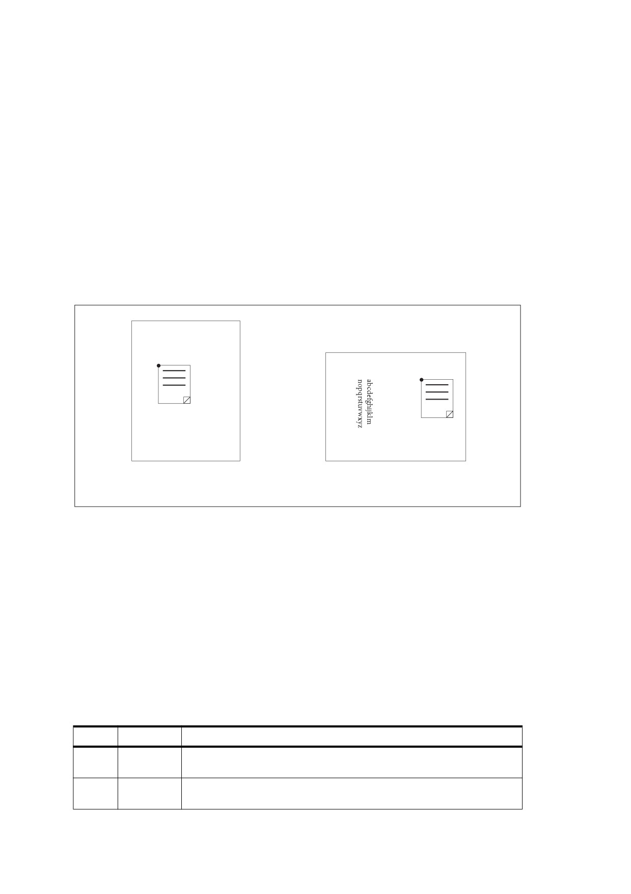
If the NoZoom flag is set, the annotation shall always maintain the same fixed size on the screen and shall be
unaffected by the magnification level at which the page itself is displayed. Similarly, if the NoRotate flag is set,
the annotation shall retain its original orientation on the screen when the page is rotated (by changing the
Rotate entry in the page object; see 7.7.3, “Page Tree”).
In either case, the annotation’s position shall be determined by the coordinates of the upper-left corner of its
annotation rectangle, as defined by the Rect entry in the annotation dictionary and interpreted in the default
user space of the page. When the default user space is scaled or rotated, the positions of the other three
corners of the annotation rectangle are different in the altered user space than they were in the original user
space. The conforming reader shall perform this alteration automatically. However, it shall not actually change
the annotation’s Rect entry, which continues to describe the annotation’s relationship with the unscaled,
unrotated user space.
NOTE
Figure 58 shows how an annotation whose NoRotate flag is set remains upright when the page it is on is
rotated 90 degrees clockwise. The upper-left corner of the annotation remains at the same point in default user
space; the annotation pivots around that point.
(0, 0)
abcdefghijklm
nopqrstuvwxyz
(0, 0)
Before page rotation
After page rotation
Figure 58 - Coordinate adjustment with the NoRotate flag
12.5.4
Border Styles
An annotation may optionally be surrounded by a border when displayed or printed. If present, the border shall
be drawn completely inside the annotation rectangle. In PDF 1.1, the characteristics of the border shall be
specified by the Border entry in the annotation dictionary (see Table 164). Beginning with PDF 1.2, the border
characteristics for some types of annotations may instead be specified in a border style dictionary designated
by the annotation’s BS entry. Such dictionaries may also be used to specify the width and dash pattern for the
lines drawn by line, square, circle, and ink annotations. Table 166 summarizes the contents of the border style
dictionary. If neither the Border nor the BS entry is present, the border shall be drawn as a solid line with a
width of 1 point.
Table 166 - Entries in a border style dictionary
Key
Type
Value
Type
name
(Optional) The type of PDF object that this dictionary describes; if present,
shall be Border for a border style dictionary.
W
number
(Optional) The border width in points. If this value is 0, no border shall drawn.
Default value: 1.
386
Table 166 - Entries in a border style dictionary (continued)
Key
Type
Value
S
name
(Optional) The border style:
S
(Solid) A solid rectangle surrounding the annotation.
D
(Dashed) A dashed rectangle surrounding the annotation. The dash
pattern may be specified by the D entry.
B
(Beveled) A simulated embossed rectangle that appears to be raised
above the surface of the page.
I
(Inset) A simulated engraved rectangle that appears to be recessed
below the surface of the page.
U
(Underline) A single line along the bottom of the annotation rectangle.
A conforming reader shall tolerate other border styles that it does not
recognize and shall use the default value.
D
array
(Optional) A dash array defining a pattern of dashes and gaps that shall be
used in drawing a dashed border (border style D in the S entry). The dash
array shall be specified in the same format as in the line dash pattern
parameter of the graphics state (see 8.4.3.6, “Line Dash Pattern”). The dash
phase is not specified and shall be assumed to be 0.
EXAMPLE
A D entry of [ 3 2 ] specifies a border drawn with 3-point
dashes alternating with 2-point gaps.
Default value: [ 3 ].
Beginning with PDF 1.5, some annotations (square, circle, and polygon) may have a BE entry, which is a
border effect dictionary that specifies an effect that shall be applied to the border of the annotations. Beginning
with PDF 1.6, the free text annotation may also have a BE entry. Table 167 describes the entries in a border
effect dictionary.
Table 167 - Entries in a border effect dictionary
Key
Type
Value
S
name
(Optional) A name representing the border effect to apply. Possible values
are:
S No effect: the border shall be as described by the annotation dictionary’s
BS entry.
C The border should appear “cloudy”. The width and dash array specified by
BS shall be honored.
Default value: S.
I
number
(Optional; valid only if the value of S is C) A number describing the intensity of
the effect, in the range 0 to 2. Default value: 0.
12.5.5
Appearance Streams
Beginning with PDF 1.2, an annotation may specify one or more appearance streams as an alternative to the
simple border and colour characteristics available in earlier versions. Appearance streams enable the
annotation to be presented visually in different ways to reflect its interactions with the user. Each appearance
stream is a form XObject (see 8.10, “Form XObjects”): a self-contained content stream that shall be rendered
inside the annotation rectangle.
The algorithm outlined in this sub-clause shall be used to map from the coordinate system of the appearance
XObject (as defined by its Matrix entry; see Table 97) to the annotation’s rectangle in default user space:
387
Algorithm: Appearance streams
a) The appearance’s bounding box (specified by its BBox entry) shall be transformed, using Matrix, to
produce a quadrilateral with arbitrary orientation. The transformed appearance box is the smallest upright
rectangle that encompasses this quadrilateral.
b) A matrix A shall be computed that scales and translates the transformed appearance box to align with the
edges of the annotation’s rectangle (specified by the Rect entry). A maps the lower-left corner (the corner
with the smallest x and y coordinates) and the upper-right corner (the corner with the greatest x and y
coordinates) of the transformed appearance box to the corresponding corners of the annotation’s
rectangle.
c) Matrix shall be concatenated with A to form a matrix AA that maps from the appearance’s coordinate
system to the annotation’s rectangle in default user space:
AA = Matrix ¥ A
The annotation may be further scaled and rotated if either the NoZoom or NoRotate flag is set (see 12.5.3,
“Annotation Flags”). Any transformation applied to the annotation as a whole shall also applied to the
appearance within it.
Starting with PDF 1.4, an annotation appearance may include transparency. If the appearance’s stream
dictionary does not contain a Group entry, it shall be treated as a non-isolated, non-knockout transparency
group. Otherwise, the isolated and knockout values specified in the group dictionary
(see
11.6.6,
“Transparency Group XObjects”) shall be used.
The transparency group shall be composited with a backdrop consisting of the page content along with any
previously painted annotations, using a blend mode of Normal, an alpha constant of 1.0, and a soft mask of
None.
NOTE 1
If a transparent annotation appearance is painted over an annotation that is drawn without using an
appearance stream, the effect is implementation-dependent. This is because such annotations are sometimes
drawn by means that do not conform to the PDF imaging model. Also, the effect of highlighting a transparent
annotation appearance is implementation-dependent.
An annotation may define as many as three separate appearances:
•
The normal appearance shall be used when the annotation is not interacting with the user. This
appearance is also used for printing the annotation.
•
The rollover appearance shall be used when the user moves the cursor into the annotation’s active area
without pressing the mouse button.
•
The down appearance shall be used when the mouse button is pressed or held down within the
annotation’s active area.
NOTE 2
As used here, the term mouse denotes a generic pointing device that controls the location of a cursor on the
screen and has at least one button that can be pressed, held down, and released. See 12.6.3, “Trigger
Events,” for further discussion.
The normal, rollover, and down appearances shall be defined in an appearance dictionary, which in turn is the
value of the AP entry in the annotation dictionary (see Table 164). Table 168 shows the contents of the
appearance dictionary.
388

Table 168 - Entries in an appearance dictionary
Key
Type
Value
N
stream or dictionary
(Required) The annotation’s normal appearance.
R
stream or dictionary
(Optional) The annotation’s rollover appearance. Default value: the
value of the N entry.
D
stream or dictionary
(Optional) The annotation’s down appearance. Default value: the value
of the N entry.
Each entry in the appearance dictionary may contain either a single appearance stream or an appearance
subdictionary. In the latter case, the subdictionary shall define multiple appearance streams corresponding to
different appearance states of the annotation.
EXAMPLE
An annotation representing an interactive check box may have two appearance states named On and Off.
Its appearance dictionary may be defined as
/AP <<
/N <<
/On formXObject1
/Off formXObject2
>>
/D
<<
/On formXObject3
/Off formXObject4
>>
>>
where formXObject1 and formXObject2 define the check box’s normal appearance in its checked and
unchecked states, and formXObject3 and formXObject4 provide visual feedback, such as emboldening its
outline, when the user clicks it. (No R entry is defined because no special appearance is needed when the
user moves the cursor over the check box without pressing the mouse button.) The choice between the
checked and unchecked appearance states is determined by the AS entry in the annotation dictionary
(see Table 164).
NOTE 3
If a conforming reader does not have native support for a particular annotation type conforming readers shall
display the annotation with its normal (N) appearance. Conforming readers shall also attempt to provide
reasonable behavior (such as displaying nothing) if an annotation’s AS entry designates an appearance state
for which no appearance is defined in the appearance dictionary.
For convenience in managing appearance streams that are used repeatedly, the AP entry in a PDF document’s
name dictionary (see 7.7.4, “Name Dictionary”) may contain a name tree mapping name strings to appearance
streams. The name strings have no standard meanings; no PDF objects may refer to appearance streams by
name.
12.5.6
Annotation Types
12.5.6.1
General
PDF supports the standard annotation types listed in Table 169. The following sub-clauses describe each of
these types in detail.
The values in the first column of Table 169 represent the value of the annotation dictionary’s Subtype entry.
The third column indicates whether the annotation is a markup annotation, as described in 12.5.6.2, “Markup
Annotations.” The sub-clause also provides more information about the value of the Contents entry for
different annotation types.
389

Table 169 - Annotation types
Annotation type
Description
Markup
Discussed in sub-clause
Text
Text annotation
Yes
12.5.6.4, “Text Annotations”
Link
Link annotation
No
12.5.6.5, “Link Annotations”
FreeText
(PDF 1.3) Free text annotation
Yes
12.5.6.6, “Free Text Annotations”
Line
(PDF 1.3) Line annotation
Yes
12.5.6.7, “Line Annotations”
Square
(PDF 1.3) Square annotation
Yes
12.5.6.8, “Square and Circle
Annotations”
Circle
(PDF 1.3) Circle annotation
Yes
12.5.6.8, “Square and Circle
Annotations”
Polygon
(PDF 1.5) Polygon annotation
Yes
12.5.6.9, “Polygon and Polyline
Annotations”
PolyLine
(PDF 1.5) Polyline annotation
Yes
12.5.6.9, “Polygon and Polyline
Annotations”
Highlight
(PDF 1.3) Highlight annotation
Yes
12.5.6.10, “Text Markup Annotations”
Underline
(PDF 1.3) Underline
Yes
12.5.6.10, “Text Markup Annotations”
annotation
Squiggly
(PDF 1.4) Squiggly-underline
Yes
12.5.6.10, “Text Markup Annotations”
annotation
StrikeOut
(PDF 1.3) Strikeout annotation
Yes
12.5.6.10, “Text Markup Annotations”
Stamp
(PDF 1.3) Rubber stamp
Yes
12.5.6.12, “Rubber Stamp Annotations”
annotation
Caret
(PDF 1.5) Caret annotation
Yes
12.5.6.11, “Caret Annotations”
Ink
(PDF 1.3) Ink annotation
Yes
12.5.6.13, “Ink Annotations”
Popup
(PDF 1.3) Pop-up annotation
No
12.5.6.14, “Pop-up Annotations”
FileAttachment
(PDF 1.3) File attachment
Yes
12.5.6.15, “File Attachment Annotations”
annotation
Sound
(PDF 1.2) Sound annotation
Yes
12.5.6.16, “Sound Annotations”
Movie
(PDF 1.2) Movie annotation
No
12.5.6.17, “Movie Annotations”
Widget
(PDF 1.2) Widget annotation
No
12.5.6.19, “Widget Annotations”
Screen
(PDF 1.5) Screen annotation
No
12.5.6.18, “Screen Annotations”
PrinterMark
(PDF 1.4) Printer’s mark
No
12.5.6.20, “Printer’s Mark Annotations”
annotation
TrapNet
(PDF 1.3) Trap network
No
12.5.6.21, “Trap Network Annotations”
annotation
Watermark
(PDF 1.6) Watermark
No
12.5.6.22, “Watermark Annotations”
annotation
3D
(PDF 1.6) 3D annotation
No
13.6.2, “3D Annotations”
Redact
(PDF 1.7) Redact annotation
Yes
12.5.6.23, “Redaction Annotations”
390

12.5.6.2
Markup Annotations
As mentioned in 12.5.2, “Annotation Dictionaries,” the meaning of an annotation’s Contents entry varies by
annotation type. Typically, it is the text that shall be displayed for the annotation or, if the annotation does not
display text, an alternate description of the annotation’s contents in human-readable form. In either case, the
Contents entry is useful when extracting the document’s contents in support of accessibility to users with
disabilities or for other purposes (see 14.9.3, “Alternate Descriptions”).
Many annotation types are defined as markup annotations because they are used primarily to mark up PDF
documents (see Table 170). These annotations have text that appears as part of the annotation and may be
displayed in other ways by a conforming reader, such as in a Comments pane.
Markup annotations may be divided into the following groups:
•
Free text annotations display text directly on the page. The annotation’s Contents entry specifies the
displayed text.
•
Most other markup annotations have an associated pop-up window that may contain text. The annotation’s
Contents entry specifies the text that shall be displayed when the pop-up window is opened. These
include text, line, square, circle, polygon, polyline, highlight, underline, squiggly-underline, strikeout, rubber
stamp, caret, ink, and file attachment annotations.
•
Sound annotations do not have a pop-up window but may also have associated text specified by the
Contents entry.
When separating text into paragraphs, a CARRIAGE RETURN (0Dh) shall be used and not, for example, a
LINE FEED character (0Ah).
NOTE 1
A subset of markup annotations is called text markup annotations (see 12.5.6.10, “Text Markup Annotations”).
The remaining annotation types are not considered markup annotations:
•
The pop-up annotation type shall not appear by itself; it shall be associated with a markup annotation that uses it to
display text.
NOTE 2
If an annotation has no parent, the Contents entry shall represent the text of the annotation, otherwise it shall
be ignored by a conforming reader.
•
For all other annotation types (Link, Movie, Widget, PrinterMark, and TrapNet), the Contents entry shall
provide an alternate representation of the annotation’s contents in human-readable form, which is useful
when extracting the document’s contents in support of accessibility to users with disabilities or for other
purposes (see 14.9.3, “Alternate Descriptions”).
Table 170 lists entries that apply to all markup annotations.
Table 170 - Additional entries specific to markup annotations
Key
Type
Value
T
text string
(Optional; PDF 1.1) The text label that shall be displayed in the title bar of
the annotation’s pop-up window when open and active. This entry shall
identify the user who added the annotation.
Popup
dictionary
(Optional; PDF 1.3) An indirect reference to a pop-up annotation for
entering or editing the text associated with this annotation.
391
Table 170 - Additional entries specific to markup annotations (continued)
Key
Type
Value
CA
number
(Optional; PDF 1.4) The constant opacity value that shall be used in
painting the annotation (see Sections 11.2, “Overview of Transparency,”
and 11.3.7, “Shape and Opacity Computations”). This value shall apply to
all visible elements of the annotation in its closed state (including its
background and border) but not to the pop-up window that appears when
the annotation is opened.
The specified value shall not used if the annotation has an appearance
stream (see 12.5.5, “Appearance Streams”); in that case, the appearance
stream shall specify any transparency. (However, if the compliant viewer
regenerates the annotation’s appearance stream, it may incorporate the
CA value into the stream’s content.)
The implicit blend mode (see 11.3.5, “Blend Mode””) is Normal. Default
value: 1.0.
If no explicit appearance stream is defined for the annotation, it may be
painted by implementation-dependent means that do not necessarily
conform to the PDF imaging model; in this case, the effect of this entry is
implementation-dependent as well.
RC
text string
(Optional; PDF 1.5) A rich text string (see 12.7.3.4, “Rich Text Strings”)
or text
that shall be displayed in the pop-up window when the annotation is
stream
opened.
CreationDate
date
(Optional; PDF
1.5) The date and time
(7.9.4,
“Dates”) when the
annotation was created.
IRT
dictionary
(Required if an RT entry is present, otherwise optional; PDF 1.5) A
reference to the annotation that this annotation is “in reply to.” Both
annotations shall be on the same page of the document. The relationship
between the two annotations shall be specified by the RT entry.
If this entry is present in an FDF file (see 12.7.7, “Forms Data Format”), its
type shall not be a dictionary but a text string containing the contents of
the NM entry of the annotation being replied to, to allow for a situation
where the annotation being replied to is not in the same FDF file.
Subj
text string
(Optional; PDF 1.5) Text representing a short description of the subject
being addressed by the annotation.
RT
name
(Optional; meaningful only if IRT is present; PDF 1.6) A name specifying
the relationship
(the
“reply type”) between this annotation and one
specified by IRT. Valid values are:
R
The annotation shall be considered a reply to the annotation
specified by IRT. Conforming readers shall not display replies
to an annotation individually but together in the form of
threaded comments.
Group The annotation shall be grouped with the annotation specified
by IRT; see the discussion following this Table.
Default value: R.
IT
name
(Optional; PDF
1.6) A name describing the intent of the markup
annotation. Intents allow conforming readers to distinguish between
different uses and behaviors of a single markup annotation type. If this
entry is not present or its value is the same as the annotation type, the
annotation shall have no explicit intent and should behave in a generic
manner in a conforming reader.
Free text annotations (Table 174), line annotations (Table 175), polygon
annotations (Table 178), and (PDF 1.7) polyline annotations (Table 178)
have defined intents, whose values are enumerated in the corresponding
tables.
392