Volkswagen Golf Variant / Jetta. Manual - part 273


  Index      Volkswagen     Volkswagen Golf Variant (2007), Jetta (2005) - service repair manual


Search            


Content   ..  271  272  273  274   ..


Volkswagen Golf Variant / Jetta. Manual - part 273


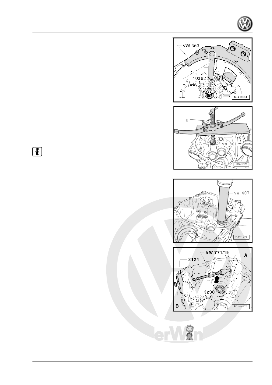
Removing the Reverse Shaft Needle Sleeve from the Transmis‐

sion Housing
A - Internal Puller - 23.5 - 30 mm , for example Puller - Kukko

Internal - 20-30mm - 21/4-
B - Counter Support , for example, Puller - Kukko Counterstay -

22/2-

Note

The needle sleeve will get damaged when it is removed and must

be replaced.

Installing the Needle Sleeve -A- into the Transmission Housing
– While installing, place thrust washer -B- for the reverse shaft

onto the needle sleeve.

– Support the transmission housing with the Press Piece -

37mm - VW416B- directly under the bearing mount.

Removing the Selector Shaft Bearing Bushing
– Use the thread adapter from Puller - Kukko Counterstay - 22/1-

-arrow-.

– Hold the spindle on the Subframe Support Tool - 3290- and

turn the nut -B-.

A - 14.5 to 18.5 mm Internal Puller , for example Puller - Kukko

Internal - 14-19mm - 21/2-

12. Transmission Housing, Servicing    

267

to the Tool

Removing the Plug -1-
– Remove the plug -1- from the inside of the transmission hous‐

ing to the outside.

Installing the Plug -1-
– Using the Bearing Installer - Crankshaft Pilot Bearing - 3264- ,

drive in the sealing plugs to dimension -a- approximately 3 mm

below the upper edge of the housing.

268

Clutch Housing, Servicing

Special tools and workshop equipment required
♦ Press Piece - Rod - VW407-
♦ Bushing Driver - Selector Shaft - T10168-
♦ Seal Installer - Driveshaft - T40008-
♦ Puller - Kukko Internal - 14-19mm - 21/2-
♦ Puller - Kukko Internal - 20-30mm - 21/4-
♦ Puller - Kukko Counterstay - 22/1-
♦ Puller - Kukko Counterstay - 22/2-

1 - Bearing Bushing

❑ For the selector rods
❑ Always replace if re‐

moved

❑ Removing. Refer to

⇒ Fig. ““Removing the

Shift Rod Bearing Bush‐

ing”“ , page 271

 .

❑ Installing. Refer to

⇒ Fig. ““Installing the

Shift Rod Bearing Bush‐

ing All the Way onto the

Tool”“ , page 271

 .

2 - Axle for the Reverse Gear

Shift Fork

❑ The axle cannot be re‐

moved with workshop

tools.

❑ A new axle must be in‐

stalled when using a

new clutch housing. Re‐

fer to

⇒ Fig. ““Installing the

Axle for the Reverse

Gear Shift Fork into the

Clutch Housing”“ ,

page 272

❑ Mount the reverse gear

shift fork on the axle.

Refer to

⇒ Fig. ““The Reverse

Gear Shift Fork -1- is

Mounted on the

Axle -2- behind the 5th

and 6th Gear Shift

Rod -3-.”“ , page 254

❑ Bearing on the shift rod

for the 5th and 6th gear shift fork. Refer to

⇒ Fig. ““The Reverse Gear Shift Fork -1- is Mounted on the Gearshift Rod with the 5th and 6th Gear Shift

Fork -2-.”“ , page 254

❑ Refer to the Parts Catalog.

3 - Needle Sleeve

❑ For the reverse shaft
❑ Always replace if removed
❑ Removing. Refer to 

⇒ Fig. ““Removing the Needle Sleeve from the Clutch Housing”“ , page 271

 .

13. Clutch Housing, Servicing    

269

⇒ Fig. ““Installing the Needle Sleeve -A- into the Clutch Housing”“ , page 271

 .

4 - Alignment Sleeve

❑ Quantity: 2

5 - Clutch Housing

❑ When replacing: adjust the output shafts and differential. Refer to

⇒ “4 Overview - Adjustment”, page 393

6 - Input Shaft Seal

❑ Removing. Refer to 

⇒ Fig. ““Remove the Seal for the Input Shaft”“ , page 272

 .

❑ Installing. Refer to 

⇒ Fig. ““Installing the Seal for the Input Shaft”“ , page 272

 .

7 - Seal

❑ FWD - for the right flange shaft

♦ Replace the right flange shaft for FWD. Refer to 

⇒ “1.2 Right Flange Shaft Seal, Replacing”, page 370

❑ For the bevel box for AWD vehicles; between the manual transmission and the bevel box

♦ Replace if the manual transmission is installed and for AWD vehicles. Refer to

⇒ “2.3 Bevel Box Seal, Replacing, with Manual Transmission Installed”, page 375

♦ Remove using the Puller - Crankshaft/Power Steering Seal - 2 - T20143/2-
♦ Can be driven in to the stop with a Seal Installer - Crankshaft - T40007- in a disassembled transmission.
8 - Washer

❑ For the differential
❑ Installed position: shoulder on inner diameter faces toward seal -item 7- 

⇒ Item 7 (page 270)

9 - Outer Race/Tapered Roller Bearing

❑ For the differential
❑ FWD, removing and installing. Refer to

⇒ “5.1 FWD Differential, Disassembling and Assembling”, page 394

 .

❑ AWD, removing and installing. Refer to

⇒ “5.2 Differential, AWD, Disassembling and Assembling”, page 399

 .

❑ When replacing: adjust the differential. Refer to 

⇒ “5.3 Differential, Adjusting”, page 405

10 - Oil Deflector Ring

❑ Installed position: shoulder at hole points toward output shaft

11 - Outer Race/Tapered Roller Bearing

❑ Output shaft, 1st to 4th gears
❑ Removing and installing. Refer to

⇒ “2.2 Output Shaft, 1st to 4th Gears, Disassembling and Assembling”, page 321

 .

❑ Adjust, if output shaft for 1st to 4th gear is replaced. Refer to

⇒ “2.3 Output Shaft 1st through 4th Gear, Adjusting”, page 340

 .

12 - Outer Race/Tapered Roller Bearing

❑ Output shaft, 5th/6th and reverse gears
❑ Removing and installing. Refer to

⇒ “3.1 Overview - Input Shaft, 5th/6th and Reverse Gears”, page 344

 .

❑ When replacing: adjust output shaft for 5th/6th and reverse gear. Refer to

⇒ “3.3 Output Shaft, 5th, 6th and Reverse Gears, Adjusting”, page 353

 .

13 - Washer

❑ Output shaft, 5th/6th and reverse gears
❑ Always 0.65 mm thick

14 - Cylindrical Roller Bearing

❑ For the input shaft
❑ Removing and installing. Refer to 

⇒ “1.1 Overview - Input Shaft”, page 310

 .

15 - Magnet

❑ Held in place by housing joint surface

270


Content   ..  271  272  273  274   ..