Volkswagen Golf Variant / Jetta. Manual - part 274


  Index      Volkswagen     Volkswagen Golf Variant (2007), Jetta (2005) - service repair manual


Search            


Content   ..  272  273  274  275   ..


Volkswagen Golf Variant / Jetta. Manual - part 274


❑ Not on all clutch housings

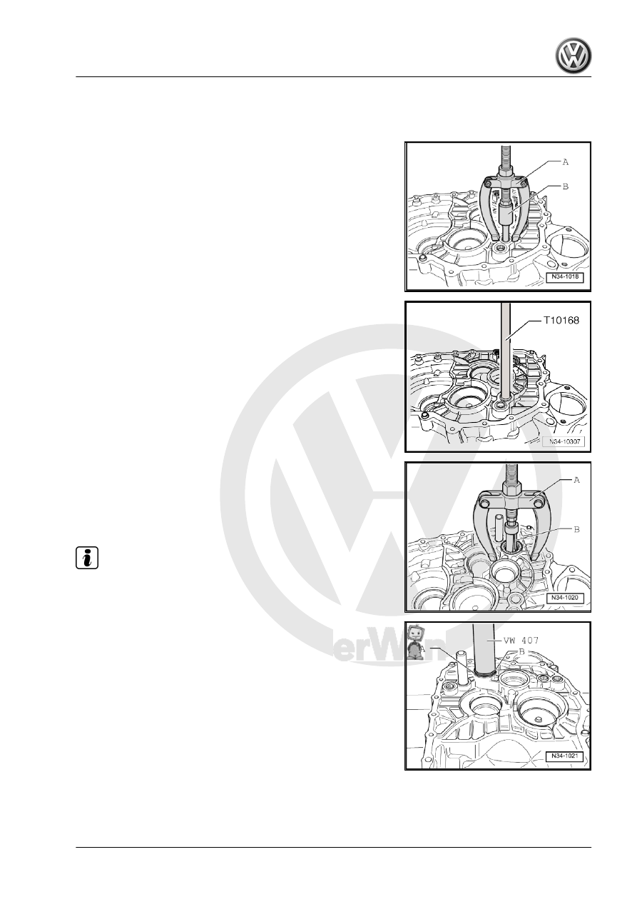
Removing the Shift Rod Bearing Bushing
A - Counter Support , for example Puller - Kukko Counterstay -

22/1-
B - 14.5 to 18.5 mm Internal Puller , for example Puller - Kukko

Internal - 14-19mm - 21/2-

Installing the Shift Rod Bearing Bushing All the Way onto the Tool

Removing the Needle Sleeve from the Clutch Housing
A - Counter Support , for example, Puller - Kukko Counterstay -

22/2-
B - Internal Puller - 23.5 - 30 mm , for example Puller - Kukko

Internal - 20-30mm - 21/4-

Note

The needle sleeve will get damaged when it is removed and must

be replaced.

Installing the Needle Sleeve -A- into the Clutch Housing
– While installing, place thrust washer -B- for the reverse shaft

onto the needle sleeve.

13. Clutch Housing, Servicing    

271

Note

Use the drift to remove the seal with the clutch housing removed.

Installing the Seal for the Input Shaft

Installing the Axle for the Reverse Gear Shift Fork into the Clutch

Housing

272

Shift Unit, Servicing

⇒ “14.1 Selector Shaft Seal, Replacing”, page 274

Note

Lubricate the bearing areas and sliding surfaces.

Refer to the Parts Catalog for the grease allocation.

1 - Hex Nut

❑ 23 Nm
❑ Self-locking
❑ Replace after removing

2 - Selector Lever

❑ Insert so that master

spline aligns with shift

rod

❑ Can be replaced with

the shift mechanism still

installed

❑ Installation position. Re‐

fer to

⇒ Fig. ““Selector Lever/

Relay Lever Installed

Position”“ , page 88

 .

❑ Installing. Refer to

⇒ Fig. ““Installing the

Transmission Shift Lev‐

er”“ , page 88

 .

❑ Adjust the gearshift

mechanism after instal‐

ling. Refer to

⇒ “1.11 Selector Mech‐

anism, Adjusting”,

page 97

 .

3 - Sliding Shoe

❑ Attached into the relay

lever -item 5-

⇒ Item 5 (page 273)

4 - Bearing Bushing

❑ Not needed for the plas‐

tic relay lever

5 - Relay Lever

❑ Installation position. Refer to 

⇒ Fig. ““Selector Lever/Relay Lever Installed Position”“ , page 88

 .

❑ Adjust the gearshift mechanism after installing. Refer to

⇒ “1.11 Selector Mechanism, Adjusting”, page 97

 .

❑ Plastic relay lever from 05/2007. Refer to 

⇒ “1.8 Plastic Relay Lever”, page 89

 .

6 - Gearshift Unit

❑ Consisting of the gearshift shaft and the gearshift cover
❑ The components cannot be separated from each other
❑ Can be removed and installed with the transmission installed
❑ Gearshift shaft adapted together with the revised reverse gear shift fork bearing -item 5-

⇒ Item 5 (page 277)

❑ Allocation, gearshift shafts. Refer to 

⇒ Fig. ““Allocation, Gearshift Shafts”“ , page 274

14. Shift Unit, Servicing    

273

❑ For the selector shaft
❑ Removing and installing -item 16- 

⇒ Item 16 (page 263)

 .

8 - O-Ring

❑ Insert in the groove in the shift cover
❑ Install with transmission fluid
❑ Replace after removing

9 - Cap

❑ For the transmission ventilation

10 - Lock Washer

❑ For the relay lever
❑ Not on the plastic relay lever
❑ Replace after removing

11 - Gearshift Shaft Seal

❑ Replacing. Refer to 

⇒ “14.1 Selector Shaft Seal, Replacing”, page 274

 .

Allocation, Gearshift Shafts

Number of Selector Fingers

on the Selector Shaft

Bearing, Reverse Gear Shift

Fork

Fig.-A-= 2 shift fingers

-arrow 1- and -arrow 2-

On the axle for the reverse gear

shift fork. Refer to

⇒ Fig. ““The Reverse Gear Shift

Fork -1- is Mounted on the

Axle -2- behind the 5th and 6th

Gear Shift Rod -3-.”“ ,

page 254

Fig. -B- = 1 shift finger

-arrow 3-

Gearshift rod with shift fork for

5th and 6th gear. Refer to

⇒ Fig. ““The Reverse Gear Shift

Fork -1- is Mounted on the Gear‐

shift Rod with the 5th and 6th

Gear Shift Fork -2-.”“ ,

page 254

14.1

Selector Shaft Seal, Replacing

Special tools and workshop equipment required
♦ Press Piece - Shift Rod/Alternator - VW423-
♦ Puller - Crankshaft/Power Steering Seal - 1 - T20143/1-
♦ Sealing Grease - G 052 128 A1-
– Remove entire air filter housing if it is located above the se‐

Gr.  24 ; Air Filter; Air Filter Housing, Removing and Installing .

274


Content   ..  272  273  274  275   ..