Toyota Tundra (2019 year). Manual - part 9
129
3
Opera
Your preferred driving position (the position of the driver’s seat, steer-
ing wheel and outside rear view mirrors) can be recorded and recalled
by pressing a button.
Two different driving positions can be recorded into memory.
■
Recording procedure
Check that the shift lever is in P.
Turn the engine switch to the “ON” position.
Adjust the driver’s seat, steering wheel, and outside rear view
mirrors to the desired positions.
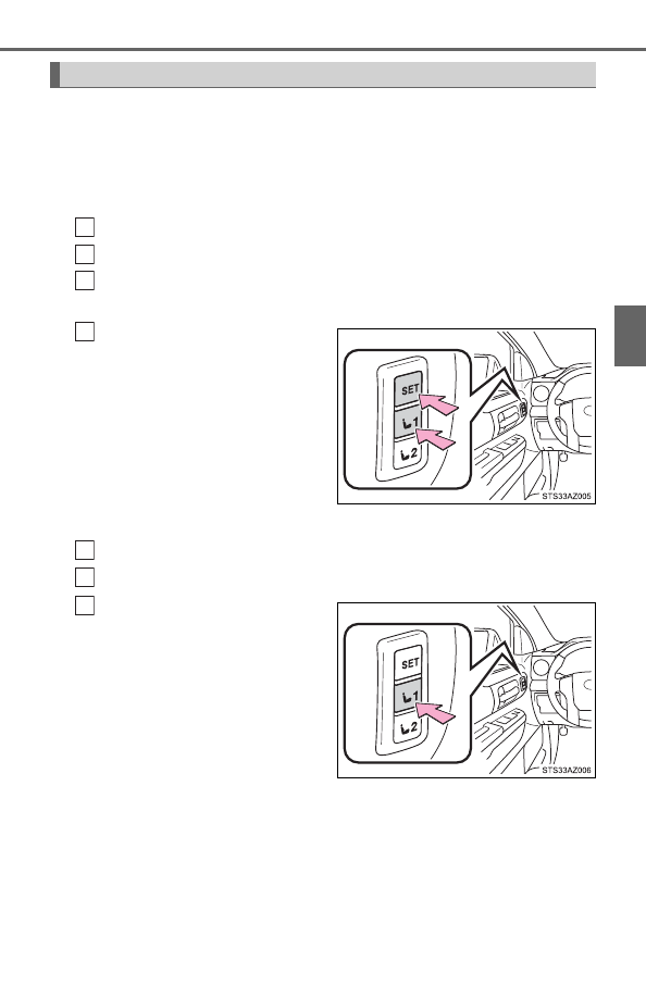
While pressing the “SET”
button, or within 3 seconds
after the “SET” button is
pressed, press button “1” or
“2” until the buzzer sounds.
If the selected button has
already been preset, the previ-
ously recorded position will be
overwritten.
■
Recall procedure
Check that the shift lever is in P.
Turn the engine switch to the “ON” position.
Press one of the buttons for
the driving position you want
to recall until the buzzer
sounds.
Driving position memory
1
2
3
4
1
2
3