Renault Kangoo Z.E. (2018 year). Manual - part 7
2.4
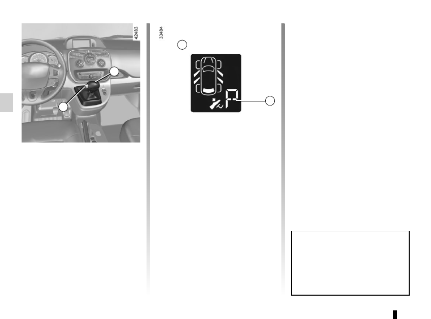
GEAR CONTROL
(1/2)
Operates similar to an automatic gear-
box.
Selector lever 1
The display A on instrument panel indi-
cates the gear lever position as 3.
P : Park
R : Reverse
N : Neutral
D : Forward
Operation
Keeping your foot on the brake pedal
and with the selector lever 1 in position
P, turn the ignition.
Start the motor.
To move out of position P, you must de-
press the brake pedal before pressing
unlocking button 2.
With your foot on the brake pedal
(warning light
c
in display A goes
out), move the lever out of position P.
Only engage D or R when the vehi-
cle is stopped, with your foot on the
brake and the accelerator pedal re-
leased.
1
Driving
Put lever 1 in position D.
Hill start
For hill starts, especially after a maxi-
mum traction battery charge and for the
first few miles, we recommend using
the handbrake.
While driving, press the accelerator
pedal to achieve the desired speed.
Reverse
Put lever 1 in position R.
The reversing lights will come on as
soon as reverse gear is selected (with
the ignition on).
3
2
A
The vehicle can only start if the gear
selector is in position P.
The vehicle can only be started if
the charging cord is unplugged from
the vehicle.