Renault Kangoo Z.E. (2018 year). Manual - part 8
2.20
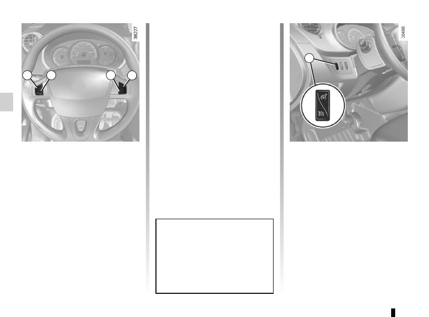
SPEED LIMITER
(3/3)
Putting the function on
standby
The speed limiter function is suspended
when you press switch 4 (O). In this
case, the limit speed remains stored
and the message “SPEED MEMORY”
accompanied by this speed appears on
the instrument panel.
Recalling the limit speed
If a speed has been stored, it can be re-
called by pressing switch 5 (R).
When the speed limiter is put on
standby, pressing switch 2 (+) re-
activates the function without taking
into account the stored speed: it is
the speed at which the vehicle is
moving that is taken into account.
Switching off the function
The speed limiter function is deacti-
vated when you press switch 1. In this
case, the speed is no longer stored.
The orange instrument panel warning
light
goes out, confirming that the
function is stopped.
1
2
4
5
3