Renault Kangoo VAN Z.E. (2012 year). Manual - part 11
5.15
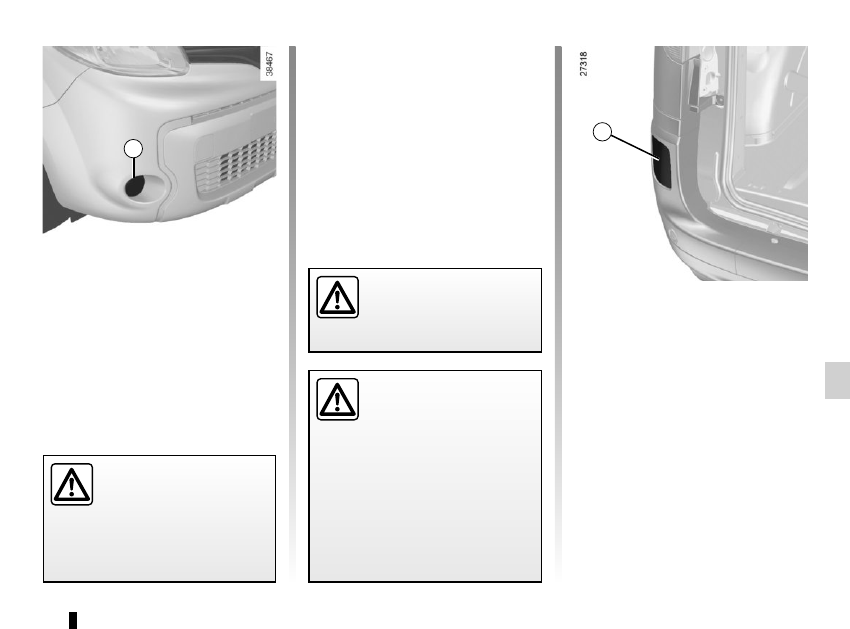
Front fog lights 1
As it is necessary to remove parts or
components (front bumper), you are
advised to have your bulbs replaced
by an approved dealer.
Bulb type: H16
Additional lights
If you wish to fit your car with fog lights
or long range headlights, contact an au-
thorised dealer.
FOG LIGHTS: changing bulbs
1
The engine may be hot
during operations in close
proximity. In addition, the
engine cooling fan may
start at any moment.
Risk of injury.
Any operation on (or modi-
fication to) the electrical
system must be performed
by an approved dealer
since an incorrect connection might
damage the electrical equipment
(harness, components and in partic-
ular the alternator). In addition, your
Dealer has all the parts required for
fitting these units.
Rear fog lights 2
As it is necessary to remove parts or
components (rear bumper), you are
advised to have your bulbs replaced
by an approved dealer.
Bulb type: P21 W
2
The bulbs are under pres-
sure and can break when
replaced.
Risk of injury.