Nissan Quest (2017 year). Manual - part 8
2-28
Instruments and controls
SIC3993
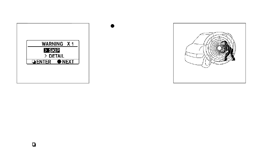
Warning check
To see if there are any of the following warnings
and corresponding details, select this menu.
. No key warning
. Low fuel warning
. Low washer fluid warning
. Parking brake release warning
. Door/liftgate open warning
. Loose fuel cap warning
. Check tire pressure warning
SKIP:
Push the
switch
*
A
to move to the warning
check mode.
Push the
switch
*
B
to select other menus.
DETAIL:
This item is available only when a warning is
displayed.
Select this menu to see the details of warnings.
SIC4717
Your vehicle has two types of security systems,
as follows:
. Vehicle security system
. NISSAN Vehicle Immobilizer System
The security condition will be shown by the
security indicator light.
VEHICLE SECURITY SYSTEM
The vehicle security system provides visual and
audio alarm signals if someone opens the doors
or liftgate when the system is armed. It is not,
however, a motion detection type system that
activates when a vehicle is moved or when a
vibration occurs.
The system helps deter vehicle theft but cannot
SECURITY SYSTEMS