Ford Orion. Manual - part 54


  Index      Ford     Ford Orion - service and repair manual


Search            


Content   ..  52  53  54  55   ..


Ford Orion. Manual - part 54


11 Disconnect the multi-plug from the rear of
the module, and remove the module from the
vehicle. 

Warning: Position the air bag
module in a safe place, with the
mechanism facing downwards as
a precaution against accidental
operation.

12 Undo the four screws, and remove the
steering column lower shroud.
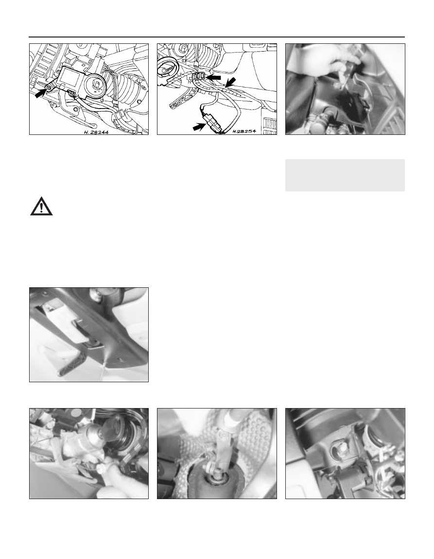
13 Undo the screws and withdraw the
detachable lower facia panel from beneath
the steering column (see illustration).
14 Where applicable, undo the single screw
and withdraw the Passive Anti-Theft 

System (PATS) transceiver from the
iignition switch/steering lock barrel (see
illustration)
.
15 Release the steering column wiring
harness from the retaining clips, and
disconnect the air bag module wiring harness
multi-plug (see illustration).
16 Turn the steering wheel so that the
roadwheels are in the straightahead position,
then remove the ignition key to lock the
steering.
17 Unscrew the retaining bolt from the centre
of the steering wheel, then insert the ignition
key and turn it to position “I”. Grip the steering
wheel each side, then pull and withdraw it
from the column shaft. If the wheel is reluctant
to budge, give it a sharp tap on the underside
of the spoke (as near to the hub as possible)
with the palm of your hand.

Refitting

All models

18 Refit in the reverse order of removal.
Ensure that the indicator stalk is set in its
central (off) position, to avoid damaging it with
the tag of the wheel as it is pushed down the
shaft. Make sure that the wheel is centralised,
as noted on removal. Turn the ignition key so
that it is in position “I” (steering unlocked).
Tighten the retaining bolt to the specified
torque setting.

21 Steering column 

removal and refitting

3

Removal

Disconnect the battery negative (earth) lead
(refer to Chapter 5, Section 1).
Remove the steering wheel as described in
the previous Section.
Remove the screws and withdraw the
steering column upper and lower shrouds
(see illustrations).
Remove the multi-function switch assembly
from the column, with reference to Chapter
12.
Disconnect the ignition switch multi-plug,
and release the wiring from the wiring loom
guide.
Detach the bonnet release cable from the
lever, then remove the lever from the column
(see illustration).
Unscrew and remove the clamp bolt
securing the steering column to the pinion
shaft (see illustration).
Loosen off the column lower retaining nuts,
then unscrew and remove the upper retaining
nuts (see illustration). Remove the steering
column from the vehicle.

Refitting

Refitting is a reversal of the removal
procedure, but note the following:

10•14 Suspension and steering systems

21.8  Steering column upper retaining nut

(on the left-hand side of the column)

21.7  Steering column-to-pinion shaft

coupling and clamp bolt

21.6  Detach the bonnet release cable from

the lever

21.3B  . . . and lower steering column

shrouds

21.3A  Remove the upper . . .

20.15  Release the steering column wiring

harness and multi-plug as indicated

20.14  Undo the screw (arrowed) and

withdraw the Passive Anti-Theft System

(PATS) transceiver from the ignition

switch/steering lock barrel

a)

Tighten the respective retaining bolts to
their specified torque settings.

b)

Check that the steering is centralised with
the wheels in the straightahead position
before refitting the steering wheel as
described in Section 20.

c)

Refit the steering wheel before securing
the steering column coupling to the pinion
shaft with the clamp bolt.

d)

Ensure that the wiring connections are
securely made. On completion, check for
satisfactory operation of the steering, the
column switches and the horn.

22 Steering column -

dismantling and reassembly

3

Dismantling

Remove the steering column as described
in the previous Section, then securely locate it
in a vice fitted with protective jaws.
Remove the upper thrust bearing tolerance
ring from the column, then withdraw the
column shaft from the column tube.
Insert the ignition key into the lock/switch,
and turn it to the “I” position. Now use a small
screwdriver or a suitable rod to depress the
plunger in the side of the barrel, and simul-
taneously pull on the key to withdraw the
lock/switch from the column (see
illustration)
.
Withdraw the spring from the column shaft.
Prise free the lower and upper thrust
bearings from the column tube and the
lock/switch body.
To remove the steering column height
adjuster (where fitted) unscrew the through-
bolt and locknut, remove the handle and
lockplates, then remove the adjuster from the
column.
If any part of the steering column (and in
particular, the universal joints) is found to be
excessively worn, or if any part of the column
assembly has been damaged, it must be
renewed; no repairs are possible.

Reassembly

Reassembly is a reversal of the dismantling
procedure, but note the following points:

a)

When refitting the height adjuster, coat
the threads of the through-bolt with
Loctite, and locate the handle in the
locked position. Tighten the retaining bolt
and nut securely.

b)

Take care when fitting the lower thrust
bearing into the column tube and the
upper bearing to the steering lock/ignition
switch body.

c)

When fitting the steering column
lock/ignition switch, ensure that the key is
in the “I” position. As the switch/lock is
fitted into its barrel, it may be necessary
to move the key clockwise and anti-
clockwise slightly, to enable the housing
drive to align with the barrel and fully
engage.

d)

When assembling the column shaft to the
tube, ensure that the upper thrust bearing
tolerance ring is fitted with its tapered
face towards the bearing.

23 Steering gear rubber 

gaiters - renewal

3

Remove the track rod end balljoint and its
locknut from the track rod as described in
Section 28.
Release the clip(s), and slide the gaiter off
the rack-and-pinion housing and track rod
(see illustration).
Scrape off all grease from the old gaiter,
and apply to the track rod inner joint. Wipe

clean the seating areas on the rack-and-
pinion housing and track rod.
Slide the new gaiter onto the housing and
track rod, and tighten the clip(s).
Refit the track rod end balljoint as
described in Section 28.

24 Steering gear 

(manual steering) 
removal and refitting

4

Removal

Disconnect the battery negative (earth) lead
(refer to Chapter 5, Section 1).
Refer to Section 10 for details, and remove
the subframe from the vehicle as described.
Note that complete removal of the subframe
may not be necessary if it is carefully lowered
to allow access to the steering gear for its
separation and withdrawal.
Unscrew and remove the two steering gear-
to-subframe retaining bolts, then withdraw the
assembly from the vehicle (see illustrations).

Refitting

Refit the steering gear to the subframe in
the reverse order of removal, and tighten the
retaining bolts to the specified torque setting.
Refer to Section 10 for the relevant details
on refitting the subframe assembly to the
vehicle.

25 Steering gear 

(power-assisted steering) -
removal and refitting

4

Removal

Disconnect the battery negative (earth) lead
(refer to Chapter 5, Section 1).
Refer to Section 10 and proceed as
described in paragraphs 1 to 12 inclusive,
then proceed as follows.
Undo the retaining screws, and detach the
clips securing the power steering hydraulic
pressure pipes to the steering gear.
Position a suitable container under the
hydraulic pipe connections to the steering

Suspension and steering systems  10•15

23.2  Steering gear gaiter and retaining

clips (arrowed)

22.3  Releasing the steering lock

24.3B  Steering gear retaining bolt

(arrowed) to the subframe on the left-hand

side

24.3A  Steering gear retaining bolt

(arrowed) to the subframe on the right-

hand side

10

gear. Unscrew the bolt securing the hydraulic
valve clamp plate to the valve body on the
steering rack, then detach the pipes from the
valve body. Withdraw the pipes from the
steering gear, and drain the hydraulic fluid into
the container (see illustration).
Plug the exposed ends of the hydraulic line
connections, to prevent the ingress of dirt and
further fluid loss. Note that new O-ring seals
will be needed for the pressure and return
hose connections when reconnecting.
Locate suitable jacks or blocks under the
subframe to support it, then unscrew and
remove the eight subframe fixing bolts (see
illustration 10.14). 
Lower the support jacks or
blocks, and withdraw the subframe. As it is
lowered, disengage the steering gear shaft
from the column. Note that complete removal
of the subframe from the vehicle may not be
necessary if it is carefully lowered to allow
access to the steering gear for its separation
and withdrawal.
Unscrew and remove the two steering gear-
to-subframe retaining bolts, then withdraw the
from the vehicle.

Refitting

Refit the steering gear to the subframe in
the reverse order of removal, and tighten 
the retaining bolts to the specified torque
setting.
Refer to Section 10 for the relevant details,
and refit the subframe assembly to the
vehicle. When the subframe is loosely in
position, remove the temporary plugs from
the hydraulic fluid lines, and check that the
connections are clean. Fit new O-ring seals to
the pressure and return hoses, then reconnect
the hydraulic lines to the steering gear. Check
that the hydraulic lines and fixings are secure,
then continue refitting the steering gear and
subframe as described in Section 10.
10 On completion, top up the power steering
fluid reservoir and bleed the system as
described in Section 27. Check for any signs
of fluid leakage from the system hoses and
connections. Finally check and adjust the
front wheel alignment as described in Sec-
tion 29.

26 Power-assisted steering

pump - removal and refitting

1

Removal

Disconnect the battery negative (earth) lead
(refer to Chapter 5, Section 1).
On Zetec engine models, undo the two
bolts and remove the drivebelt upper guard
from the top of the pump (see illustration).
Apply the handbrake, then raise and
support the front of the vehicle on axle
stands.
Undo the retaining screws, and remove the
drivebelt lower guard from the underbody.
Loosen off the drivebelt tension by turning
the tension adjustment bolt in a clockwise
direction. Noting the routing of the belt around
the pulleys, disengage the drivebelt from the
power steering pump pulley.
Position a suitable container beneath the
power steering pump, then unscrew and
detach the fluid pressure and return hoses
from the pump (see illustration). As they are
detached from the pump, allow the fluid to
drain from the hoses (and the pump) into the
container. Plug the exposed ends of the
hydraulic hoses and the pump connections, to
prevent the ingress of dirt and excessive fluid
loss.
Insert a 9 mm Allen key into the centre of
the pump drive spindle to prevent it from
turning, then unscrew and remove the three

pump pulley retaining bolts (see illustration).
Withdraw the pulley from the pump.
Unscrew the four retaining bolts shown
(see illustration) and withdraw the pump
from the vehicle.

Refitting

Refitting is a reversal of removal, but tighten
all nuts and bolts to the specified torque.
Remove the plugs from the pipes, and ensure
that the pipes are located correctly so that
they do not foul any surrounding components.
10 Refit the drivebelt as described in Chap-
ter 1.
11 On completion, fill the power steering
system with the specified fluid up to the
maximum level mark, and bleed the system as
described in Section 27. Check for any signs
of fluid leakage from the system hoses and
connections.

27 Power-assisted steering

system - bleeding

1

This will normally only be required if any
part of the hydraulic system has been
disconnected.
Remove the fluid reservoir filler cap, and
top-up the fluid level to the “max-cold” mark
using only the specified fluid (refer to
“Lubricants, fluids and capacities” at the
beginning of this manual).
Start the engine and allow it to idle, slowly

10•16 Suspension and steering systems

26.8  Power steering pump and securing

bolts

26.7  Power steering pump pulley removal

26.6  Power steering pump and hose

connections on the CVH engine

26.2  Remove the drivebelt upper guard

from the top of the power steering pump

on Zetec engines

25.4  Power steering gear and hydraulic

pipe connections

A

Hydraulic pipe locating clips

B Valve clamp plate bolt

moving the steering from lock-to-lock several
times to purge out the air, then top-up the
level in the fluid reservoir. Add the fluid slowly,
to prevent the possibility of aeration of the
fluid in the circuit.
Switch the engine off, then recheck the fluid
level in the reservoir, and further top-up if
necessary. Finally check the system hoses
and connections for any signs of fluid leaks,
which if found, must be rectified.

28 Track rod end balljoint -

removal and refitting

3

Removal

Apply the handbrake, then jack up the front
of the vehicle and support it on axle stands.
Remove the appropriate front roadwheel.
Using a suitable spanner, slacken the track
rod end balljoint locknut on the track rod by a
quarter of a turn (see illustration). Hold the
balljoint stationary with another spanner
engaged with the flats at its inner end to
prevent it from turning.
Extract the split pin, then loosen off the
retaining nut. If the balljoint is to be renewed,
the nut can be fully removed. If the existing
balljoint is to be reconnected, the nut should
be slackened off a couple of turns only at first,
and left in position to protect the joint threads
as the joint is separated from the spindle
carrier. To release the tapered shank of the
joint from the spindle carrier, use a balljoint
separator tool as shown (see illustration). If
the joint is to be re-used, take care not to
damage the rubber dust cover when using a
separator tool.
Count the number of exposed threads
visible on the inner section of the track rod,
and record this figure.
Unscrew the balljoint from the track rod,
counting the number of turns necessary to
remove it.

Refitting

Screw the balljoint into the track rod the

number of turns noted during removal until the
balljoint just contacts the locknut. Now tighten
the locknut while holding the balljoint.
Engage the shank of the balljoint with the
spindle carrier arm, and refit the locknut.
Tighten the locknut to the specified torque. If
the balljoint shank turns while the locknut is
being tightened, lever down on the top of the
balljoint with a stout bar. The tapered fit of the
shank will lock it and prevent rotation as the
nut is tightened.
Refit the roadwheel, and lower the vehicle
to the ground.
Finally check and if necessary adjust the
front wheel alignment with reference to
Section 29.

29 Wheel alignment and

steering angles 
general information

4

Accurate front wheel alignment is essential
to provide positive steering and prevent
excessive tyre wear. Before considering the
steering/suspension geometry, check that the
tyres are correctly inflated, that the front
wheels are not buckled, and that the steering
linkage and suspension joints are in good
order, without slackness or wear.
Wheel alignment consists of four factors
(see illustration):

Camber is the angle at which the front

wheels are set from the vertical when viewed
from the front of the vehicle. “Positive
camber” is the amount (in degrees) that the
wheels are tilted outward at the top of the
vertical.

Castor is the angle between the steering

axis and a vertical line when viewed from each
side of the car. “Positive castor” is when the
steering axis is inclined rearward at the top.

Steering axis inclination is the angle (when

viewed from the front of the vehicle) between
the vertical and an imaginary line drawn
through the suspension strut upper mounting
and the lower suspension arm balljoint.

Toe setting is the amount by which the

distance between the front inside edges of the

roadwheels (measured at hub height) differs
from the diametrically-opposite distance
measured between the rear inside edges of
the front roadwheels.
With the exception of the toe setting, all
other steering angles are set during
manufacture, and no adjustment is possible. It
can be assumed, therefore, that unless the
vehicle has suffered accident damage, all the
preset steering angles will be correct. Should
there be some doubt about their accuracy, it
will be necessary to seek the help of a Ford
dealer, as special gauges are needed to
check the steering angles.
Two methods are available to the home
mechanic for checking the toe setting. One
method is to use a gauge to measure the
distance between the front and rear inside
edges of the roadwheels. The other method
is to use a scuff plate, in which each front
wheel is rolled across a movable plate which

Suspension and steering systems  10•17

29.2  Wheel alignment and steering angles

28.3  Balljoint separator tool in position.

Note that the nut should be left loosely in
position when the thread of the joint is to

be protected for re-use

28.2  Track rod end balljoint showing the

locknut (A) retaining flats (B) and the

balljoint-to-spindle carrier arm retaining

nut and split pin (C)

10


Content   ..  52  53  54  55   ..