Ford Orion. Manual - part 52


  Index      Ford     Ford Orion - service and repair manual


Search            


Content   ..  50  51  52  53   ..


Ford Orion. Manual - part 52


Open and support the bonnet. Prise free
the protective cap from the strut upper
retaining nut, then loosen off, but do not
remove
, the central retaining nut. As the nut is
loosened off, hold the strut piston rod with an
Allen key to prevent the rod from turning as
the nut is loosened (see illustrations).
Detach the front brake hose from the
support bracket on the strut.
Where applicable, unbolt and detach the
anti-roll bar link rod from the suspension strut.
Unscrew and remove the strut-to-spindle
carrier clamp bolt.
Note the direction of fitting, then unscrew
and remove the lower arm balljoint-to-spindle
carrier clamp bolt. Prise the joint open using a
large flat-bladed tool, and detach the balljoint
from the spindle carrier. Take care not to
damage the balljoint seal during the
separation procedures.
Prise open the spindle carrier-to-strut joint,
and separate the carrier from the strut. Tap
the carrier downwards using a soft-faced
hammer to release it from the strut if
necessary.
Support the weight of the strut underneath,
and unscrew the two nuts securing it to the
turret at the top. Lower the strut and remove it
from the vehicle.

Refitting

Refitting is a reversal of removal. Tighten all
the retaining bolts to the specified torque.
When reconnecting the suspension lower arm
balljoint to the spindle carrier, ensure that the
clamp bolt is fully engaged in the locating
groove, and prevent the bolt from turning as
the nut is tightened.

7

Front suspension strut -
dismantling, examination and
reassembly

4

Note: Before attempting to dismantle the front
suspension strut, a tool to hold the coil spring
in compression must be obtained. The Ford
tool is shown in the accompanying
illustrations, however careful use of
conventional coil spring compressors will
prove satisfactory.

Dismantling

With the strut removed from the vehicle,
clean away all external dirt, then mount it
upright in a vice.
Fit the spring compressor tool (ensuring
that it is fully engaged) and compress the coil
spring until all tension is relieved from the
upper mounting (see illustration).
Hold the strut piston with an Allen key, and
unscrew the nut with a ring spanner.
Withdraw the cup, retainer (top mounting),
the bearing and upper spring seat, followed
by the gaiter and the bump stop (see
illustration)
.
The suspension strut and coil spring can now
be separated. If a new coil spring or strut is to
be fitted, the original coil spring must be
released from the compressor. If it is to be re-
used, the coil spring can be left in compression.

Examination

With the strut assembly now completely
dismantled, examine all the components for
wear, damage or deformation, and check the
bearing for smoothness of operation. Renew
any of the components as necessary.
Examine the strut for signs of fluid leakage.
Check the strut piston for signs of pitting
along its entire length, and check the strut
body for signs of damage or elongation of the
mounting bolt holes. Test the operation of the
strut, holding it in an upright position, by
moving the piston through a full stroke, and
then through short strokes of 50 to 100 mm.
In both cases, the resistance felt should be
smooth and continuous. If the resistance is
jerky, or uneven, or if there is any visible sign
of wear or damage to the strut, renewal is
necessary.

10•6 Suspension and steering systems

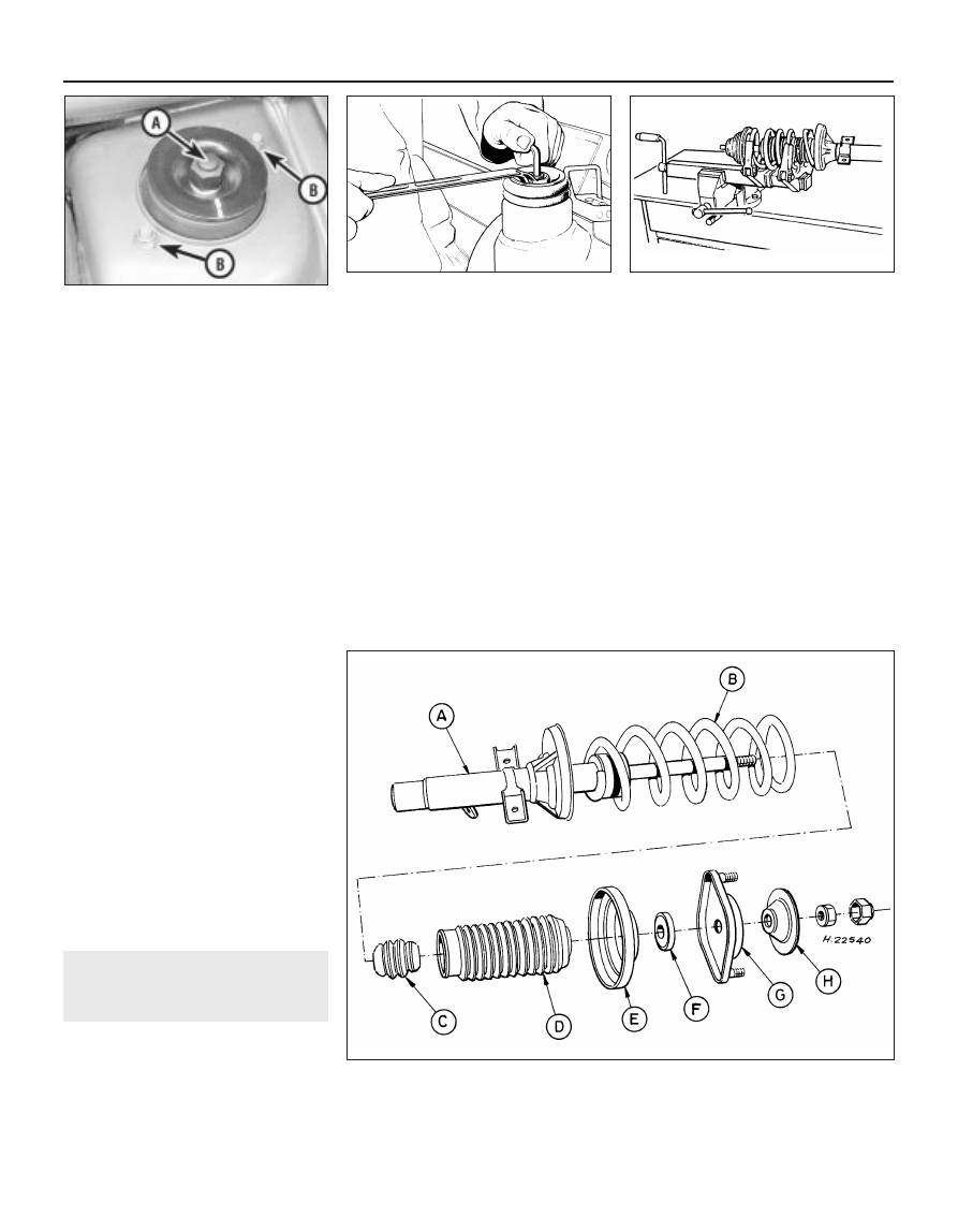
7.4  Front suspension strut components

7.2  Ford special tool in use to compress

the front suspension strut coil spring

6.2B  Method to use when loosening off

the strut upper mounting

6.2A  Front suspension strut upper

mounting showing the protective cap over

retaining nut (A) and the strut-to-body

mounting nuts (B)

A

Strut

B Spring
C Bump stop

D Gaiter
E

Upper spring seat

F

Bearing

G Top mounting retainer
H Top mounting cup

Reassembly

Reassembly is a reversal of dismantling, but
make sure that the spring ends are correctly
located in the upper and lower seats (see
illustrations)
. Check that the bearing is
correctly fitted to the piston rod seat. Tighten
the upper nut to the specified torque.

8

Front suspension anti-roll
bar 
- removal and refitting

2

Removal

Apply the handbrake, then jack up the front
of the vehicle and support it on axle stands.
Remove the front roadwheels.
Unscrew the retaining nut, and detach the
link rod from the suspension strut each side
(see illustration).
Similarly, detach the link rod from the anti-
roll bar each side (see illustration).
Unscrew the retaining nuts, and remove the
anti-roll bar mounting brackets from the
subframe each side, then withdraw the anti-
roll bar from the side (see illustration).
Check the bar for damage, and the rubber
bushes for wear and deterioration. If the
bushes are in need of renewal, slide them off
the bar, and fit new ones after lubricating
them with rubber grease. If the link rod
bushes are in poor or suspect condition, they
will have to be renewed complete with the link
rods.

Refitting

Refitting is a reversal of the removal
procedure. Tighten the retaining nuts to the
specified torque setting.

9

Front suspension lower arm
- removal and refitting

3

Removal

Apply the handbrake, then jack up the front
of the vehicle and support it on axle stands.
Remove the appropriate roadwheel.
Note the direction of fitting, then unscrew
and remove the lower arm balljoint-to-spindle
carrier clamp bolt. Prise the joint open using a
large flat-bladed tool, and detach the balljoint
from the spindle carrier. Take care not to
damage the balljoint seal during the
separation procedures.
Unscrew and remove the inboard retaining
bolts on the subframe, and withdraw the
suspension arm from it (see illustration).
If the balljoint and/or the inboard mounting
bushes are found to be in poor condition, the
complete suspension arm must be renewed.
The suspension arm must also be renewed if
it has suffered structural damage.

Refitting

Refitting is a reversal of the removal
procedure, but note the following special
points:

a)

When reconnecting the arm to the
subframe, the bolts must be fitted from
underneath, and hand-tightened until the
vehicle is resting on its wheels.

b)

When reconnecting the suspension lower
arm balljoint to the spindle carrier, ensure
that the clamp bolt is fully engaged in the
locating groove, and prevent the bolt from
turning as the nut is tightened.

c)

Fully tighten the suspension arm-to-
subframe bolts when the vehicle is
lowered and is standing on its wheels.
These bolts must then be tightened in the
sequence specified.

10 Subframe 

removal and refitting

4

Removal

Apply the handbrake, then jack up the front
of the vehicle and support it on axle stands.
Remove the front roadwheels.
Disconnect the battery negative (earth) lead
(refer to Chapter 5, Section 1).
Fit an engine support bar (or a sling and
hoist) to support the combined weights of the
engine and transmission when the subframe
is detached (as during engine/transmission
removal and refitting).
Centralise the steering so that it is in the
straightahead position, then working within
the vehicle, unscrew and remove the steering
column-to-pinion shaft clamp bolt.

Suspension and steering systems  10•7

8.2  Link rod-to-strut connection

7.8B  Spring end location in the upper seat

7.8A  Spring location in the lower seat

9.3  Suspension arm-to-subframe retaining

bolts (arrowed)

8.4  Anti-roll bar-to-subframe mounting

8.3  Link rod-to-bar connection

10

Undo the engine/transmission mounting
bracket bolts at the subframe connection (see
illustration)
.
Where applicable, disconnect the oxygen
sensor wiring multi-plug, then undo the
retaining nuts and detach the exhaust
downpipe (Chapter 4).
Disconnect the gear linkage at the
transmission (Chapter 7).
Extract the split pin and unscrew the track
rod end balljoint nut on each side, then using
a conventional separator tool, detach each
joint from its spindle carrier connection.
Note the direction of fitting, then unscrew
and remove the lower arm balljoint-to-spindle
carrier clamp bolt. Prise the joint open using a
large flat-bladed tool, and detach the balljoint
from the spindle carrier. Take care not to
damage the balljoint seal during the
separation procedure.
10 Unscrew the retaining bolt, and detach
the right-hand engine support bar from the
subframe.
11 Referring to illustration 10.5, unscrew and
remove the second engine/transmission
mounting bolt.
12 Where applicable, unscrew the retaining
nuts and detach the anti-roll bar link rods from
the suspension strut each side.
13 Where applicable, detach the power-
assisted steering hydraulic lines from the
steering gear (refer to Section 25 for details).
14 Locate suitable support jacks or blocks
under the subframe to support it, then
unscrew and remove the eight subframe fixing

bolts from the positions shown (see
illustration)
. Lower the support jacks or
blocks and withdraw the subframe. As it is
lowered, disengage the steering pinion shaft
from the column.
15 When the subframe is lowered from the
vehicle, the steering gear, the suspension
arms and the anti-roll bar (where applicable)
can be unbolted and removed from it as
necessary.
16 If the subframe and/or its associated
components have suffered damage or are in
poor condition, they must be renewed.

Refitting

17 Refitting is a reversal of removal, but
observe the following points:
a)

Ensure that all mating faces are clean
before refitting.

b)

When raising the subframe into position,
ensure that the location dowels engage in
the guide bores in the floorpan, and
carefully engage the steering pinion shaft
with the column shaft. Check that the
various fixing bolt holes are in alignment,
then loosely insert all of the retaining bolts
before tightening them to the specified
torque setting.

c)

When reconnecting the suspension lower
arm balljoint to the spindle carrier, ensure
that the clamp bolt is fully engaged in the
locating groove, and prevent the bolt from
turning as the nut is tightened.

d)

Tighten all nuts and bolts to the specified
torque. Fit a new split pin to the track rod
end balljoint nut to secure it.

e)

On completion, check the wheel
alignment and steering angles as
described in Section 29.

11 Rear hub bearings 

checking and renewal

3

Checking

All models are fitted with non-adjustable
rear wheel bearings which are supplied pre-
greased by the manufacturer.
To check the bearings for excessive wear,
chock the front wheels, then raise and
support the rear end of the vehicle securely on
axle stands. Fully release the handbrake.
Grip the rear roadwheel at the top and
bottom, and attempt to rock it. If excessive
movement is noted, or if there is any
roughness or vibration felt when the wheel is
spun, it is indicative that the hub bearings are
in need of renewal.

Renewal

Drum brake models

Unbolt and remove the roadwheel on the
side concerned.
Check that the handbrake is still released,
then remove the rubber blanking plug from
the inside face of the brake backplate, reach
through with a suitable screwdriver, and
release the automatic brake adjuster by
levering the catch from the pawl.
On certain models, the brake drum may be
removed independently of the hub if desired.
Remove the drum retaining screw (if fitted),
and withdraw the drum off the wheel hub.
Prise free the outer grease cap from the
centre of the hub (see illustration). The cap
will be deformed during its removal, and will
need to be renewed when the hub is refitted.
Unscrew and remove the hub nut, but note
that the hub nut threads are “handed”
according to side - right-hand to right, left-
hand to left (see illustration)A left-hand
thread unscrews in a clockwise direction.
Withdraw the brake drum/hub from the
spindle of the rear stub axle (see illustration).

10•8 Suspension and steering systems

11.9  . . . and remove the brake drum

11.8  . . . unscrew the hub nut . . .

11.7  Remove the outer grease cap from

the centre of the rear hub . . .

10.14  Subframe securing bolt locations

10.5  Engine/transmission mounting

bracket securing bolt locations on the

subframe

Disc brake models

10 Unbolt and remove the roadwheel on the
side concerned.
11 Refer to Chapter 9, and remove the rear
brake pads.
12 Referring to Chapter 9, undo the two rear
brake caliper retaining bolts, and slide the
caliper off the brake disc. Tie up the caliper
using string or wire, but take care not to
stretch the flexible brake hose.
13 Undo the brake disc retaining screw, and
withdraw the disc off the handbrake shoes
and wheel hub.
14 Prise free the outer grease cap from the
centre of the hub. The cap will be deformed
during its removal, and will need to be
renewed when the hub is refitted.
15 Unscrew and remove the hub nut, but
note that the hub nut threads are “handed”
according to side - right-hand to right, left-
hand to left. A left-hand thread unscrews in a
clockwise direction.
16 Withdraw the wheel hub from the spindle
of the rear stub axle.

All models

17 Use a screwdriver or suitable lever to
prise free the grease retainer (seal) from the
hub bore, but take care not to damage the
bore surface.
18 Remove the inner and outer bearing
cones from the bore of the hub.
19 To remove the bearing cups from the hub,
drive them out using a suitable punch
(preferably one made of brass). Drive each
cup from its respective end by tapping it
alternately at diametrically-opposed points
(see illustration). Do not allow the cups to tilt
in the bore, or the surfaces may become
burred and prevent the new bearings from
seating correctly as they are fitted.
20 Clean the bore and spindle thoroughly
before reassembly.
21 To reassemble, tap the new bearing cups
into position in the hub, using a piece of
tubing slightly smaller in its outside diameter
than that of the bearing cup. Ensure that the
cups are squarely inserted and abut their
respective shoulders in the hub.
22 Pack the inner bearing cone with grease,
and insert it into its cup in the hub.

23 To fit the grease retainer (seal), first
lubricate its inner lip to ease installation, then
lightly tap the seal into position using a block
of wood. Ensure that the seal is correctly
orientated.
24 Pack the outer bearing cone with grease,
and fit it into position in its cup.
25 The brake drum/hub or separate wheel
hub (according to model) can now be refitted
to the axle spindle. Before fitting into position,
first check that the brake surface area in the
drum is free of grease and oil. Locate the
drum/hub into position, then fit the retaining
nut. Tighten it to the specified torque wrench
setting whilst simultaneously rotating the
assembly to ensure that the bearings are
correctly seated.
26 Carefully tap the new hub grease cap into
position in a progressive manner around its
outer edge until it is fully fitted.
27 On models with disc brakes or separate
brake drums, refit the disc or drum, and
secure with the retaining screw (where fitted).
28 On models with disc brakes, refit the
brake caliper and tighten the retaining bolts to
the specified torque. Refer to Chapter 9 and
refit the rear brake pads.
29 Refit the rubber blanking plug to the brake
backplate, and firmly apply the footbrake a
few times to take up the brake adjustment.
Check that the rear brakes do not bind when
the brakes are released. Refit the roadwheel,
lower the vehicle and then tighten the
retaining nuts to the specified torque wrench
setting.

12 Rear strut (Hatchback and

Saloon models) 
removal and refitting

3

Removal

Chock the front wheels, then jack up the
rear of the vehicle and support it on axle
stands. Remove the inner wheel arch trim.
On ABS-equipped models, unscrew the
retaining nut and detach the load-
apportioning valve connecting link from the
axle beam (see illustration).
Unscrew and remove the securing bolt from
the strut-to-axle mounting (see illustration).

Prise free the protective cap from the top of
the shock absorber mounting, located in the
luggage compartment (see illustration).
Unscrew and remove the two retaining nuts
to detach the strut from its upper mounting. Do
not unscrew the central upper mounting bolt.
Withdraw the suspension strut from the
vehicle.

Refitting

Refitting is a reversal of the removal
procedure, but note the following special
points:
a)

With the suspension strut located to its
upper mounting, tighten the retaining nuts
to the specified torque wrench setting.

b)

When reconnecting the suspension strut
to the lower mounting, hand-tighten the
retaining bolt, then lower the vehicle so
that it is standing on its wheels before
fully tightening the bolt to its specified
torque setting.

13 Rear strut (Hatchback and

Saloon models) - dismantling,
examination and reassembly

4

Note:  Before attempting to dismantle the
suspension strut, a tool to hold the coil spring
in compression must be obtained. A Ford tool
is available (tool No MS-1516), however
careful use of conventional coil spring
compressors will prove satisfactory.

Suspension and steering systems  10•9

11.19  Use a suitable punch to drive out the

bearing cups from the rear hub

12.4  Rear strut upper mounting on

Hatchback and Saloon models showing the

protective cap (A) and the mounting nuts (B)

12.3  Rear strut lower mounting on

Hatchback and Saloon models

12.2  Detaching the ABS load-apportioning

valve connecting link from the axle beam

on models so equipped

10


Content   ..  50  51  52  53   ..