Snowmobile Polaris Two Stroke (2007 year). Instruction - part 39


  Index      Snowmobiles / ATV     Snowmobile Polaris Two Stroke - instruction 2007 year


Search            


Content   ..  37  38  39  40   ..


Snowmobile Polaris Two Stroke (2007 year). Instruction - part 39


6.7

CLUTCHING

6

Non-ER LWT Driven Helixes

Team Helix Options with PERC
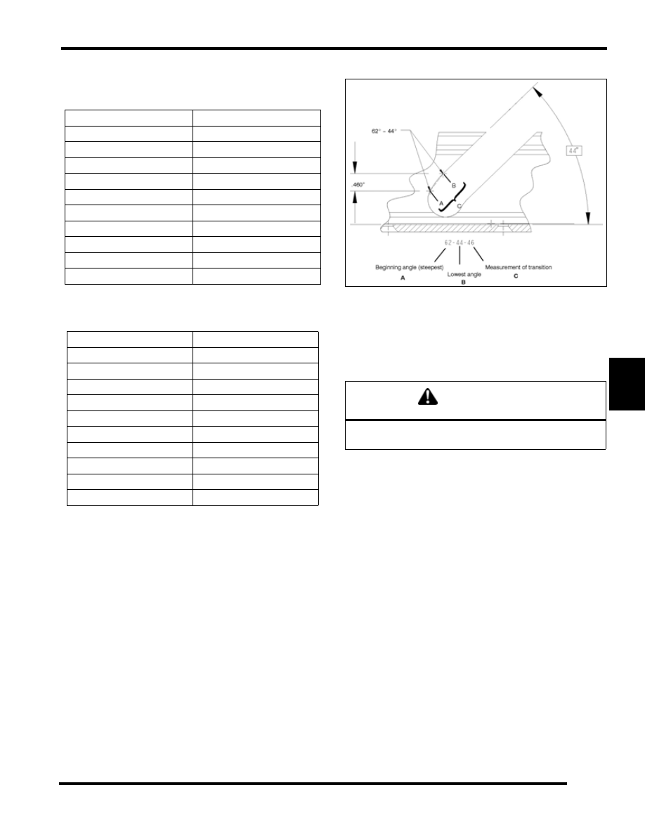
Team Ramp Angles

The Team helix is designated by the angle and length of the
angle on the back side of the ramp. The first number (A)
designates the starting angle of the ramp. The second number
(B) designates the finish angle. The last number (C) is the
transition distance (in inches) between the starting and finish
angles.

Non-ER LWT Driven Helixes

PART NUMBER

DESCRIPTION

5135438

70/44 - .46 / 66/44 - .46

5135480

64/38 - .65 / 64/38 - .46

5135486

62/40 - .46 / 64/40 - .55

5135521

74/50 - .46 / 74/48 - .46

5135522

74/44 - .46 / 74/40 - .46

5135523

70/50 - .46 / 70/48 - .46

5135524

70/44 - .46 / 70/40 - .46

5135525

66/50 - .46 / 66/48 - .46

5135526

66/44 - .46 / 66/40 - .46

5135537

64/38 - .65

PART NUMBER

DESCRIPTION

5133687

(58/44-46) ER

5133771

(58/42-46) ER

5133772

(62/46-46) ER

5133773

(62/42-46) ER

5133784

(58/40-46) ER

5133785

(62/40-46) ER

5133786

(62/44-46) ER

5133787

(62/48-46) ER

5133788

(60/44-46) ER

5133789

(60/46-46) ER

CAUTION

Do not install a non-ER helix on a Perc-equipped 

snowmobile where the engine changes directions.

6.8

CLUTCHING

Team Driven Springs

Belt Inspection

1.

Measure the belt width and replace it if it is worn severely. Generally a belt should be replaced if the clutches can no longer
be adjusted to provide the proper belt deflection.

• Project the side profiles and measure from corner to corner.

• Place a straight edge on each side of the drive belt and measure the distance where the straight edges intersect at the top 

(A,B).

2.

Inspect the belt for loose cords. missing cogs, cracks, abrasions, thin spots or excessive wear spots. Replace if necessary.

3.

Inspect the belt for hour glassing (extreme circular wear in at least one spot and on both sides of the belt). Hour glassing occurs
when the drive train does not move and the drive clutch engages the belt. Example would be taking off while the track is frozen
to the ground. Remember to always warm up the track and free it from the ground.

TEAM Driven Springs

PART NUMBER

COLOR

WIRE DIAMETER

LOAD @ 2.2

(lbs)

LOAD @ 1.1

(lbs)

Rate (Lbs. per inch)

7042181

Black/Yellow

.200

145

208

56

7043058

Red/Black

.218

140

240

90

7043059

Red/Green

.218

120

220

90

7042066

Green/Black

.200

135

198

56

7043061

Red/Silver

.207

125

175

45

7043062

Red/Yellow

.207

100

150

45

7043057

Red/Blue

.218

140

200

54

7043063

Black/Red

.218

155

222

65

7043064

Blue/Black

.218

123

203

73

7043060

Red/White

.218

100

200

91

7043069

Red/Pink

.235

140

260

110

BELT

A

B

6.9

CLUTCHING

6

Belt Wear / Burn Diagnostics

Table 6-1: 

Belt Wear / Burn Diagnostics

POSSIBLE CAUSE

SOLUTION

Driving at or about engagement RPM for extended periods 
of time in any type of snow condition.

Drive at higher RPM if possible. Gear the machine down. 
Make sure belt deflection is at 1 1/4” to achieve optimum 
starting ratio.

Cold weather startups

Be patient. Warm up engine at least 5 minutes or until it 
readily responds to throttle input. For the quickest most 
efficient drive away in extreme cold weather, take drive belt 
off machine and bring it in to a warm environment. Break 
skis and track loose from the snow. Engage throttle 
aggressively for short durations for initial cold drive away

Towing another machine at or about engagement RPM

When possible, do not go in deep snow when towing 
another machine. Use fast, effective throttle to engage the 
clutch. Not all machines are intended for pulling heavy 
loads or other machines.

Spinning track while vehicle is stuck (high RPM, low 
vehicle speed, high ambient temp. Example: 8000 RPM, 
10mph actual vehicle speed and 60 m.p.h. indicated on 
speedometer.

Lower the gear ratio. Remove windage plates from driven 
clutch. If possible, move to better snow conditions and 
reduce RPM. Avoid riding in very high ambient 
temperatures

Ice and snow piled up between track and tunnel overnight 
or after stopping for a long period of time (enough to re-
freeze the snow).

Break loose snow and ice under tunnel. Allow longer than 
normal warm-up. Allow belt to warm sufficiently and 
increase grip ability on clutch sheaves. Use fast, effective 
throttle when engaging clutch.

Poor running engine (Bog, Miss, Backfire, etc.)

Maintain good state of tune including throttle and choke 
synchronization. Check for fouled spark plug(s). Check for 
foreign material in carbs. Make sure no water or ice is 
present in the fuel tank, lines, or carburetors.

Loading machine on trailer

Use caution when loading machine. Carbide skags may 
gouge into trailer and prevent drive train from spinning 
freely. Use enough speed to drive completely onto trailer. If 
machine cannot be driven completely onto trailer, it may 
need to be pulled or pushed to avoid belt wear / burning.

Clutch malfunction

Check for correct clutch components, or damage on the 
clutch

Slow, easy belt engagement - easing on the throttle

Use fast, effective throttle to engage the clutch.

6.10

CLUTCHING

Drive Belt Removal

NOTE:  Turn the key to the “OFF” position and allow the engine to come to a complete stop.

Always install a used belt in the same direction as it was installed before removing. When installing a new belt, position the
identification numbers so they can read when viewed from the left-side of machine.

1.

Remove the clutch guard / air intake.

2.

Position the thread hole (B) so that it is in the 10:00 or 2:00 position.

3.

Insert the “L” wrench (A) into the threaded hole (B) located on the driven clutch, and turn it clockwise until the clutch sheaves
are in the open position (C).

NOTE:  L wrench PN 2874857

4.

Remove the drive belt.

Drive Belt Installation

1.

With the “L” wrench inserted into the threaded into hole (B) and the sheaves in the open position (C), install the drive belt.

NOTE:  Install belt so that the numbers can be read correctly on the left side of the machine.

2.

Turn the “L” wrench counter-clockwise until the driven clutch sheaves are in the closed position. “Wiggle” the belt to remove
slack while removing the wrench.

3.

Reinstall the clutch guard / air intake.

A

B

C

D

E


Content   ..  37  38  39  40   ..