Snowmobile Polaris Two Stroke (2007 year). Instruction - part 37


  Index      Snowmobiles / ATV     Snowmobile Polaris Two Stroke - instruction 2007 year


Search            


Content   ..  35  36  37  38   ..


Snowmobile Polaris Two Stroke (2007 year). Instruction - part 37


5.41

ENGINE

5

Specifications

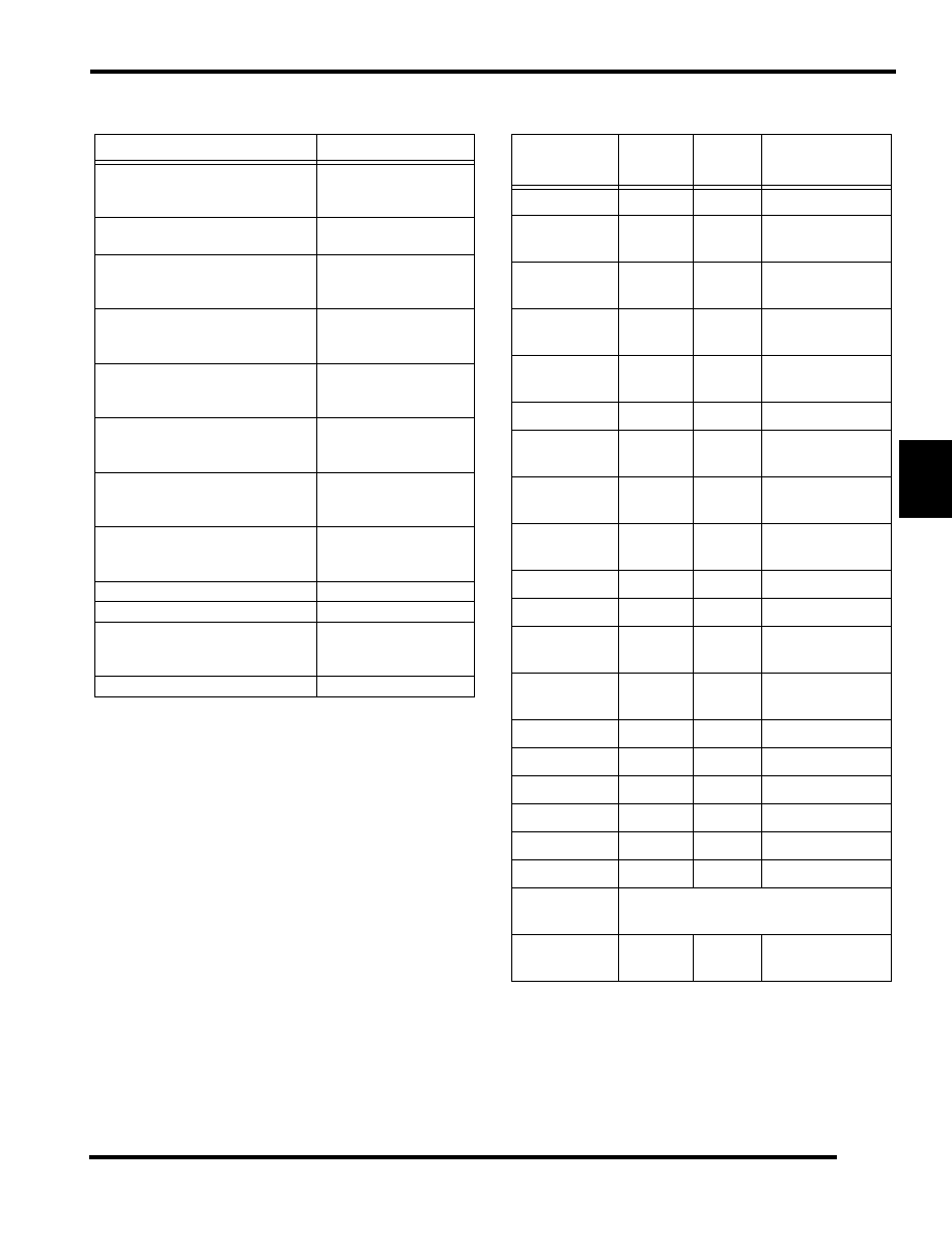
Fastener Torque Specifications

C

OMPONENT

S

PECIFICATION

Engine Model Number
- 600
- 700

S3206-6044-PF6H
S3322-7044-PF7J

Engine Type

Two Stroke CFI/Case Reed 
Induction

Cylinder Displacement
- 600
- 700

599cc
700cc

Bore - MM (Inches)
- 600
- 700

77.25 (3.04

″)

81 (3.19

″)

Stroke - MM (Inches)
- 600
- 700

64 (2.52

″)

68 (2.68

″)

Unistalled Head Volume
- 600
- 700

34.7 - 35.7cc
35.84 - 36.84cc

Installed Head Volume
- 600
- 700

31.06 - 32.56cc
31.06 - 32.56cc

Installed Head Squish
- 600
- 700

.050

″ - .064″

.050

″ - .064″

Piston-to-Cylinder Clearance

.0043

″ - .006″

Piston Ring End Gap

.012

″ - .018″

Compression Ratio (Full Stroke)
- 600
- 700

10.7 : 1
12.3 : 1

Trigger-to-Flywheel Gap

.9mm (1.34mm MAX)

C

OMPONENT

T

ORQUE


(L

B

.F

T

.)

T

ORQUE

(N-

M

)

N

OTES

Spark Plug

18

24

Thermostat 
Bleed Screw

6

8

Thermostat 
Cover

9

12

Cylinder Head 
Cover

22

30

Loctite 242

Water Temp. 
Sensor

18

24

Thread Sealant

Knock Sensor

14

19

Clean and Dry

Fuel Supply 
Rail

9

12

Cylinder Base 
Nuts

32

43

Pattern

Throttle Body 
Adapter

9

12

Oil Pump

9

12

EV Housing

12

16

Loctite 242

Exhaust 
Manifold

22

30

Water Pump 
Cover

9

12

Impeller Nut

10

13

Flywheel Cover

9

12

Recoil Pulley

9

12

Flywheel Nut

90

122

Stator

9

12

Crankcase

22

30

Pattern

Water Pump 
Bushing

Torque so screw head is flush with case.

Mounting 
Straps

35

48

Loctite 242

NOTES

ENGINE

5.42

CLUTCHING

6.1

CHAPTER 6

CLUTCHING

6

PVT SYSTEM  . . . . . . . . . . . . . . . . . . . . . . . . . . . . . . . . . . . . . . . . . . . . . . . . . . . . . . . . . . 6.2

OVERVIEW. . . . . . . . . . . . . . . . . . . . . . . . . . . . . . . . . . . . . . . . . . . . . . . . . . . . . . . . . . . . 6.2
DRIVE SPRING  . . . . . . . . . . . . . . . . . . . . . . . . . . . . . . . . . . . . . . . . . . . . . . . . . . . . . . . . 6.2
CLUTCH WEIGHT  . . . . . . . . . . . . . . . . . . . . . . . . . . . . . . . . . . . . . . . . . . . . . . . . . . . . . . 6.2
NEUTRAL SPEED  . . . . . . . . . . . . . . . . . . . . . . . . . . . . . . . . . . . . . . . . . . . . . . . . . . . . . . 6.2
ENGAGEMENT RPM . . . . . . . . . . . . . . . . . . . . . . . . . . . . . . . . . . . . . . . . . . . . . . . . . . . . 6.2
SHIFT OUT OVER-REV . . . . . . . . . . . . . . . . . . . . . . . . . . . . . . . . . . . . . . . . . . . . . . . . . . 6.2
SHIFT OUT RPM  . . . . . . . . . . . . . . . . . . . . . . . . . . . . . . . . . . . . . . . . . . . . . . . . . . . . . . . 6.2
DRIVEN SPRING . . . . . . . . . . . . . . . . . . . . . . . . . . . . . . . . . . . . . . . . . . . . . . . . . . . . . . . 6.2
BACK-SHIFTING  . . . . . . . . . . . . . . . . . . . . . . . . . . . . . . . . . . . . . . . . . . . . . . . . . . . . . . . 6.2
FINAL GEARING  . . . . . . . . . . . . . . . . . . . . . . . . . . . . . . . . . . . . . . . . . . . . . . . . . . . . . . . 6.3
1:1 SHIFT RATIO . . . . . . . . . . . . . . . . . . . . . . . . . . . . . . . . . . . . . . . . . . . . . . . . . . . . . . . 6.3
LOW / HIGH RATIO . . . . . . . . . . . . . . . . . . . . . . . . . . . . . . . . . . . . . . . . . . . . . . . . . . . . . 6.3
DRIVEN HELIX / RAMP . . . . . . . . . . . . . . . . . . . . . . . . . . . . . . . . . . . . . . . . . . . . . . . . . . 6.3

GENERAL INFORMATION . . . . . . . . . . . . . . . . . . . . . . . . . . . . . . . . . . . . . . . . . . . . . . . . 6.4

SPECIAL TOOLS . . . . . . . . . . . . . . . . . . . . . . . . . . . . . . . . . . . . . . . . . . . . . . . . . . . . . . . 6.4
DRIVE CLUTCH SPRINGS  . . . . . . . . . . . . . . . . . . . . . . . . . . . . . . . . . . . . . . . . . . . . . . . 6.5
SPRING FREE LENGTH  . . . . . . . . . . . . . . . . . . . . . . . . . . . . . . . . . . . . . . . . . . . . . . . . . 6.6
DRIVE CLUTCH WEIGHTS . . . . . . . . . . . . . . . . . . . . . . . . . . . . . . . . . . . . . . . . . . . . . . . 6.6
NON-ER LWT DRIVEN HELIXES  . . . . . . . . . . . . . . . . . . . . . . . . . . . . . . . . . . . . . . . . . . 6.7
TEAM HELIX OPTIONS WITH PERC  . . . . . . . . . . . . . . . . . . . . . . . . . . . . . . . . . . . . . . . 6.7
TEAM RAMP ANGLES . . . . . . . . . . . . . . . . . . . . . . . . . . . . . . . . . . . . . . . . . . . . . . . . . . . 6.7
TEAM DRIVEN SPRINGS  . . . . . . . . . . . . . . . . . . . . . . . . . . . . . . . . . . . . . . . . . . . . . . . . 6.8
BELT INSPECTION  . . . . . . . . . . . . . . . . . . . . . . . . . . . . . . . . . . . . . . . . . . . . . . . . . . . . . 6.8
BELT WEAR / BURN DIAGNOSTICS  . . . . . . . . . . . . . . . . . . . . . . . . . . . . . . . . . . . . . . . 6.9
DRIVE BELT REMOVAL  . . . . . . . . . . . . . . . . . . . . . . . . . . . . . . . . . . . . . . . . . . . . . . . . 6.10
DRIVE BELT INSTALLATION  . . . . . . . . . . . . . . . . . . . . . . . . . . . . . . . . . . . . . . . . . . . . 6.10
ADJUSTING BELT DEFLECTION . . . . . . . . . . . . . . . . . . . . . . . . . . . . . . . . . . . . . . . . . 6.11
DRIVE BELTS. . . . . . . . . . . . . . . . . . . . . . . . . . . . . . . . . . . . . . . . . . . . . . . . . . . . . . . . . 6.12
BLET PN 3211115 BREAK -IN PROCEEDURE. . . . . . . . . . . . . . . . . . . . . . . . . . . . . . . 6.13

PVT SYSTEM ADJUSTMENTS. . . . . . . . . . . . . . . . . . . . . . . . . . . . . . . . . . . . . . . . . . . .  6.14

CLUTCH ALIGNMENT / OFFSET  . . . . . . . . . . . . . . . . . . . . . . . . . . . . . . . . . . . . . . . . . 6.14
OFFSET ADJUSTMENT. . . . . . . . . . . . . . . . . . . . . . . . . . . . . . . . . . . . . . . . . . . . . . . . . 6.14

DRIVE CLUTCH  . . . . . . . . . . . . . . . . . . . . . . . . . . . . . . . . . . . . . . . . . . . . . . . . . . . . . . .  6.15

IDENTIFICATION . . . . . . . . . . . . . . . . . . . . . . . . . . . . . . . . . . . . . . . . . . . . . . . . . . . . . . 6.15
DRIVE CLUTCH REMOVAL. . . . . . . . . . . . . . . . . . . . . . . . . . . . . . . . . . . . . . . . . . . . . . 6.15
DRIVE CLUTCH DISASSEMBLY . . . . . . . . . . . . . . . . . . . . . . . . . . . . . . . . . . . . . . . . . . 6.16
ROLLER REMOVAL . . . . . . . . . . . . . . . . . . . . . . . . . . . . . . . . . . . . . . . . . . . . . . . . . . . . 6.17
ROLLER INSTALLATION . . . . . . . . . . . . . . . . . . . . . . . . . . . . . . . . . . . . . . . . . . . . . . . . 6.17
CLUTCH ASSEMBLY . . . . . . . . . . . . . . . . . . . . . . . . . . . . . . . . . . . . . . . . . . . . . . . . . . . 6.18
SPIDER INDEXING  . . . . . . . . . . . . . . . . . . . . . . . . . . . . . . . . . . . . . . . . . . . . . . . . . . . . 6.18
DRIVE CLUTCH INSTALLATION. . . . . . . . . . . . . . . . . . . . . . . . . . . . . . . . . . . . . . . . . . 6.20

DRIVEN CLUTCH . . . . . . . . . . . . . . . . . . . . . . . . . . . . . . . . . . . . . . . . . . . . . . . . . . . . . .  6.21

COMPONENTS  . . . . . . . . . . . . . . . . . . . . . . . . . . . . . . . . . . . . . . . . . . . . . . . . . . . . . . . 6.21
DRIVEN CLUTCH REMOVAL  . . . . . . . . . . . . . . . . . . . . . . . . . . . . . . . . . . . . . . . . . . . . 6.21
DRIVEN CLUTCH INSTALLATION  . . . . . . . . . . . . . . . . . . . . . . . . . . . . . . . . . . . . . . . . 6.21
DRIVEN CLUTCH DISASSEMBLY  . . . . . . . . . . . . . . . . . . . . . . . . . . . . . . . . . . . . . . . . 6.21
DRIVEN CLUTCH ASSEMBLY  . . . . . . . . . . . . . . . . . . . . . . . . . . . . . . . . . . . . . . . . . . . 6.22
BELT TO SHEAVE CLEARANCE INSPECTION . . . . . . . . . . . . . . . . . . . . . . . . . . . . . . 6.22
BELT TO SHEAVE CLEARANCE ADJUSTMENT . . . . . . . . . . . . . . . . . . . . . . . . . . . . . 6.22
BELT DEFLECTION INSPECTION  . . . . . . . . . . . . . . . . . . . . . . . . . . . . . . . . . . . . . . . . 6.23

6.2

CLUTCHING

PVT SYSTEM

Overview

The Polaris drive system is a centrifugally actuated variable
speed belt drive unit. The drive clutch, driven clutch, and belt
make up the torque converter system. Each clutch comes from
the factory with the proper internal components installed for its
specific engine model. Therefore, modifications or variations of
components at random are never recommended. Proper clutch
setup and adjustments of existing components must be the
primary objective in clutch operation diagnosis.

Drive Spring

The drive spring opposes the shift force generated by the clutch
weights, and determines the neutral RPM, engagement RPM,
and wether the engine RPM remains flat, rises, or falls during
shift out. When changing only the drive spring, installing a
spring with a lower pre-load rate will result in a lower
engagement RPM speed, while installing a spring with a higher
pre-load rate will result in a higher engagement RPM. 

Clutch Weight

The clutch weights generate centrifugal force as the drive clutch
rotates. The force generated changes in relation to the engine
RPM and with specified weight of each clutch weight. When
changing only the clutch weights, a lighter weight will result in
a higher engagement RPM, lower shifting force, and higher shift
out RPM. Installing heavier weights has the opposite effect

Neutral Speed

Engine RPM when the force generated by the clutch weights is
less than the pre-load force generated by the drive spring. In this
mode, the drive clutch is disengaged from the belt.

Engagement RPM

Engine RPM when the force generated by the clutch weights
overcomes the drive spring pre-load force and the moveable
sheave begins to close or “pinch” the drive belt. The

engagement mode continues until no more belt slippage occurs
in the drive clutch. Once enough belt engagement is achieved,
the sled will accelerate along the low ratio line until the drive
clutch up shift force overcomes the opposing shift force
generated by the driven clutch.

Shift Out Over-Rev

Engine RPM that spikes above the desired operating RPM
speed. The shift out RPM should come down to the desired
operating RPM, but never below, after the driven clutch begins
to open.

Shift Out RPM

Engine RPM at which the up shift force generated by the drive
clutch overcomes the shift force within the driven clutch. In this
mode, the drive clutch will move the belt outwards, and the
driven clutch will allow the drive belt to be pulled down into the
sheaves.

During WOT operation, the shift out RPM can be seen as the
maximum, sustained RPM displayed on the tachometer. The
shift out RPM should be the same RPM as the recommended
engine operating RPM. If the shift out RPM is above the
recommended engine operating RPM, install heavier drive
clutch weights. If the shift out RPM is below the recommended
engine operating RPM, install lighter drive clutch weights.

The shift out RPM should remain constant during both the
upshift and back shift modes.

Driven Spring

A compression spring (Team driven clutch) or torsional spring
(Polaris P-85 driven clutch) works in conjunction with the helix,
and controls the shift rate of the driven clutch. The spring must
provide enough side pressure to grip the belt and prevent
slippage during initial acceleration. A higher spring rate will
provide more side pressure and quicker back shifting but
decreases drive system efficiency. If too much spring tension
exists, the driven clutch will exert too much force on the belt and
can cause premature belt failure.

Back-Shifting

Back-shifting occurs when the track encounters an increased
load (demand for more torque). Back-shifting is a function of a
higher shift force within the driven clutch then within the drive
clutch. Several factors, including riding style, snowmobile
application, helix angles, and vehicle gearing determine how
efficient the drive system back-shifts. The desired engine
operating RPM should never fall below 200 RPM of engine
operating RPM, when the drive system back-shifts.

CAUTION

Because of the critical nature and precision balance in-
corporated into the PVT system, it is absolutely essen-
tial that no attempt at clutch disassembly and/or repair 
be made without factory authorized special tools and 
service procedures. Polaris recommends that only au-
thorized service technicians that have attended a Po-
laris-sponsored service training seminar and 
understand the proper procedures perform adjust-
ments or repairs.


Content   ..  35  36  37  38   ..