Snowmobile Polaris Two Stroke (2007 year). Instruction - part 36


  Index      Snowmobiles / ATV     Snowmobile Polaris Two Stroke - instruction 2007 year


Search            


Content   ..  34  35  36  37   ..


Snowmobile Polaris Two Stroke (2007 year). Instruction - part 36


5.37

ENGINE

5

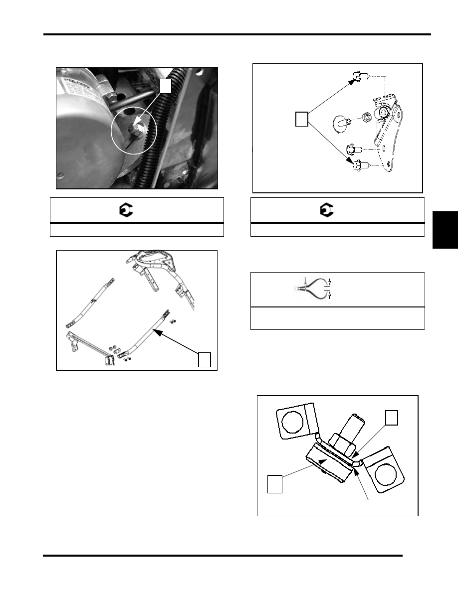
21.  Place the engine mount washers and fasteners (8) onto the

engine mount studs. Torque to specification.

22. Install the right hand chassis brace (9).

23. Apply Blue Loctite™ to the rear fasteners (10), install all

the rear torque stop fasteners and torque to specification.

24. Adjust the rear torque stop so that you have a clearance of

.010”-.030” (.25-.75mm) from the face of the torque stop
to the surface of the engine. 

NOTE:  If a new torque stop is installed, install it so
that the nub is touching the engine. This nub is .030"
(.75mm) long.

25. Adjust the engine isolator limiter (11) so that the stop is

bottomed out on the brace (12). See “Engine Isolator
Limiter Setting” on page 3.22.

T 

Engine Mount Fasteners: 28 ft.lb (37.9 N-m)

8

9

T 

Rear Torque Stop Fasteners: 28 ft.lb (37.9 N-m)

In. / mm. 

Rear Torque Stop Clearance:

.010"-.030" (.25-.75mm)

10

11

Torque Stop touching base

12

5.38

ENGINE

26. Install the front torque stop assembly and torque the plate

fasteners to specification.

27. Install the air box (13) onto the carb rack. Make sure to line

up the air box tabs with the air box plate (14).

28. Install the drive clutch. See “Drive Clutch Installation” on

page 6.20.

29. Install the driven clutch. See “Driven Clutch Installation”

on page 6.21.

30. Install the belt. See “Drive Belt Installation” on page 6.10.

31. Hook up the fuel filter and fuel return line by pushing them

together until you hear a audible “click”.

32. Secure the fuel return line “P” clamp (15) onto the side of

the airbox.

33. Place the fuel filter back into the holder (16) that is on the

airbox

34. Connect the ECU connection into the ECU.

35. Connect the EV solenoid connection to the EV solenoid.

36. Connect the coil connections to the coils. 

NOTE:   The WHITE connector (17) goes to the MAG
coil (upper). The BLUE connector (18) goes to the
PTO coil (lower).

37. Connect the regulator rectifier connections (19).

38. Connect intake air sensor (20) to the air box.

T 

Front Torque Stop Fasteners: 28 ft.lb (37.9 N-m)

14

13

15

16

18

17

19

20

5.39

ENGINE

5

39. Connect the EV solenoid vent lines back onto the EV bases

and install the panduit strap (21) around the spark plug
wires as shown.

40. Install the electrical center/belt holder over the electrical

center by aligning the rear buttons to the rear of the clutch
cover and installing the two fasteners (22).

41. Install the Nyloc nuts and two T40 Torx bolts to the front

and the two T40 to the rear of the LH and RH chassis brace
(23) and install the braces.

NOTE: Install the long bolts and the spacer on the
front portion of the bar before inserting it into the
mounting area.

42. Replace the nosepan plugs were removed to access the front

chassis brace fasteners.

43. Route the recoil rope through the eyelet on the chassis brace

and secure handle once past the console.

44. Install the exhaust system. 

45. Add coolant and bleed system. See “Cooling System

Bleeding” on page 3.7.

46. Premix the first tank of fuel. See “2 Stroke Gasoline / Oil

Pre Mix” on page 2.7.

47. Test run the unit and clear any codes with Digital Wrench.

48. After test running check drive and driven clutch torque.

21

22

23

5.40

ENGINE

Torque Specifications

When tightening bolts, nuts, or screws, a torque pattern may need to be followed to ensure uniform equal tension is applied to all
fasteners. Proper torque application prevents fasteners from loosening or breaking in critical service. It also minimizes wear and
eliminates premature or needless repair costs. Following uniform torque application sequence patterns ensures optimum
performance from precision machined, close tolerance assemblies.

The most common units of torque in the English system are ft-lb (foot pounds) and in-lb (inch pounds). In the Metric system, 
torque is commonly expressed in units of N-m (Newton Meter).

1 =Apply Loctite 242 to threads of bolt.

2= Apply Pipe sealant to threads.

3= See torque sequence.

ENGINE 600/700 CFI

SPARK PLUG

18 ft-lb (24 N-m)

CYLINDER HEAD

22ft-lb (30 N-m)1,3

BLEEDER SCREW

70 in-lb (8 N-m)

THERMOSTAT HOUSING

9 ft-lb (12 N-m)

WATER TEMPERATURE SENSOR

18-40ft-lb (24-54 N-m)2

WATER INLET PIPE

75ft-lb (102 N-m)2

DETIONATION SENSOR

168 in-lb(19 N-m)

CYLINDER BASE NUTS

32 ft-lb (43 N-m)3

EXHAUST VALVE COVER BOLTS

12 ft-lb (16 N-m)

EXHAUST VALVE NUT

 144 in-lb (16 N-m)1

EXHAUST MANIFOLD BOLTS

22 ft-lb (30 N-m)

CARB ADAPTER BOLTS

108 in-lb (12 N-m)

OIL PUMP MOUNTING BOLTS

7 ft-lb (9 N-m)

CRANCASE PLUGS

10ft-lb (14 N-m)2

WATER PUMP IMPELLER NUT

120 in-lb (14 N-m)

WATER PUMP COVER BOLTS

108 in-lb (12 N-m)

CRANKCASE 6mm

9ft-lb (12 N-m)1,3

CRANKCASE 8mm

22ft-lb (30 N-m)1,3

ENGINE STRAP to CHASSIS NUT

18ft-lb (24 N-m)

ENGINE STRAP to ENGINE BOLT

45 ft-lb (61 N-m)

STATOR BOLTS

60 in-lb(7 N-m)1

TRIGGER COIL BOLTS

48 in-lb (5 N-m)

FLYWHEEL

90ft-lb (122 N-m)1

RECOIL CUP BOLTS

108 in-lb (12 N-m)

RECOIL COVER COLTS

108 in-lb (12 N-m)

DRIVE CLUTCH BOLT

50 ft-lb(68 N-m)

7/16” ENGINE MOUNT STRAP BOLTS

45 ft-lb (61 N-m)

REAR MOTOR MOUNTS BRACKET

29 ft-lb (39 N-m)


Content   ..  34  35  36  37   ..