Snowmobile Polaris Two Stroke (2007 year). Instruction - part 34


  Index      Snowmobiles / ATV     Snowmobile Polaris Two Stroke - instruction 2007 year


Search            


Content   ..  32  33  34  35   ..


Snowmobile Polaris Two Stroke (2007 year). Instruction - part 34


5.29

ENGINE

5

600 / 700 HO CFI ENGINE

600/700 CFI Engine Removal

NOTE: Inspect all parts for wear or damage during
disassembly. Replace all seals, o-rings, and gaskets
with Genuine Pure Polaris parts during assembly. 

1.

Remove the side panels. See “SIDE PANELS” on
page 10.2.

2.

Disconnect the battery ground (-) cable from the battery if
equipped.

3.

Unplug exhaust temperature sensor and remove the exhaust
system. 

4.

Remove the spark plug leads from the spark plugs.
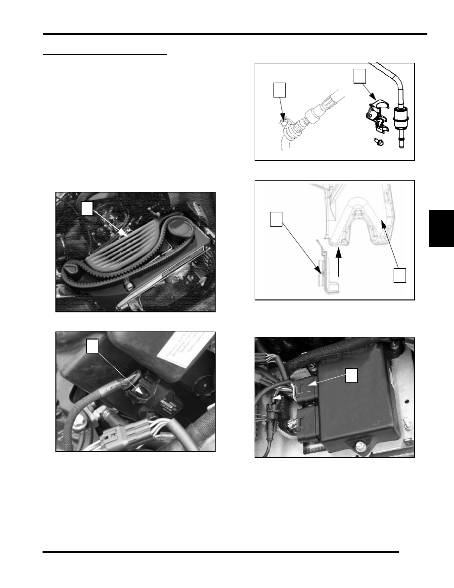
5.

Remove the belt cover/electrical center cover (1).

6.

Disconnect the intake air sensor (2) located on the MAG
side of the airbox.

7.

Remove the return fuel line “P” holder (3) located on the
MAG side of the airbox.

8.

Separate the fuel filter from the filter clip (4) that is on the
MAG side of the airbox.

9.

Remove the airbox (5) by pulling it straight out from the
air box adapter (6).

10. Disconnect the main harness (7) at the ECU. This is the

smaller of the two plugs located on the ECU. Remove it by
pressing up on the underside of the plug and pulling straight
off.

11. Disconnect the regulator rectifier connections (8).

1

2

3

4

5

6

7

5.30

ENGINE

12. Disconnect the ignition coil connections (9) and EV

solenoid from the ECU harness.

13. Disconnect the EV solenoid (10) from the ECU harness.

14. Disconnect the EV vent lines from the EV base (11) and

secure the vent lines out of the way.

15. Remove the drive belt, driven and drive clutches. See

Chapter 6.

16. Remove the recoil rope from the handle and route rope

through the guide on the chassis brace and secure the recoil
rope by tying a knot (12) so that it does not go into the recoil
housing.

17. Drain the coolant from the engine.

8

9

10

11

12

5.31

ENGINE

5

18. Remove all coolant hoses from the coolant bottle and

secure the loose hoses out of the way for engine removal.

19. Remove the four right hand chassis brace fasteners and

remove the brace (13) from the chassis.

20. Drain the oil from oil tank.

21. Remove the oil tank fasteners (14) that hold the top of the

oil tank to the chassis. 

22. Disconnect the oil supply line (15) from the oil tank, located

at the bottom portion of the oil tank. Plug and secure the
loose oil line so that it can come out with the engine.

23. Remove the engine isolator (16) and rear torque stop (17)

located on the left hand side of the engine.

24. Remove the four engine mounting fasteners (18) located on

the engine straps.

25. Remove the Schrader valve cover located under the

steering hoop (19), and depressurize the fuel rail. See “Fuel
Rail Bleeding” on page 4.20.

26. Using the fuel line disconnection tool (PN PS-47152) (20),

separate the fuel filter (21) and the fuel return line (22).

27. Secure the loose fuel lines out of the way for engine

removal.

NOTE: A helper will be needed for the following
steps.

13

14

15

16

17

18

19

600

20

21

22

5.32

ENGINE

28. Lift engine out of chassis and carefully place engine on shock tower brace.

29. While holding the engine remove the throttle bodies by loosening up the intake boot clamps and separating the throttle bodies

from the intake boots.

30. Remove the cable located in the center of the throttle bodies.

31. Remove the oil cable lock nut from the threads on the cable housing.

32. Remove the throttle cable from the oil pump bracket.

33. Remove the oil cable (23) from the oil pump lever (24) by holding the pump open and rotating the cable and keeper to the slot

in the pump arm.

34. Remove the cable from the oil pump bracket.

35. Remove the engine from the chassis.

36. Inspect the motor mounts and replace if needed. See “Engine Mount Replacement” on page 5.5.

23

24


Content   ..  32  33  34  35   ..