Suzki Burgman AN400. Manual - part 74


  Index      Motorcycles     Suzki Burgman AN400 - service and repair manual 2002 year


Search            


Content   ..  72  73  74  75   ..


Suzki Burgman AN400. Manual - part 74


8-18     ELECTRICAL SYSTEM

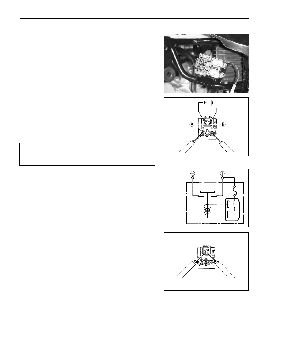
STARTER RELAY INSPECTION

• Remove the front leg shield. (

!

7-12)

• Disconnect the battery 


-

 lead wire.

• Remove the starter relay cover.
• Disconnect the starter motor read wire, battery 


+

 lead wire

and starter relay coupler.

• Remove the starter relay.

• Apply 12 V to 


A

 and 


B

 lead wires and check for continuity

between the positive and negative terminals using the multi
circuit tester. If the starter relay clicks and continuity is found,
the relay is ok.

#

09900-25008: Multi circuit tester set

+

Tester knob indication: Continuity test (

,

)

• Measure the relay coil resistance between the terminals using

the multi circuit tester. If the resistance is not within the speci-
fied value, replace the starter relay with a new one.

#

09900-25008: Multi circuit tester set

(

Tester knob indication: Resistance (

)

&

Starter relay resistance: 3 – 6 

SIDE-STAND/IGNITION INTERLOCK SYS-
TEM PARTS INSPECTION

Check the interlock system for proper operation. If the interlock
system does not operate properly, check each component for
damage or abnormalities. If any abnormality is found, replace
the component with a new one.

Do not apply a battery voltage to the starter relay for
more than five seconds, since the relay coil may over-
heat and damaged.

To starter
motor

To battery

ELECTRICAL SYSTEM     8-19

SIDE-STAND SWITCH INSPECTION

• Remove the side leg shield. (

!

7-15)

• Disconnect the side-stand switch coupler 


1

.

• Measure the voltage between green and Black/White lead

wire.
If the resistance is out of specification, replace the switch.

#

09900-25008: Multi-circuit tester set

)

Tester knob indication: Diode test (

*

)

NOTE:
If the tester reads under 1.4 V when the tester probes are not
connected, replace its battery.

SAFETY RELAY INSPECTION

• Remove the front box. (

!

7-14)

• Remove the safety relay 


1

.

• Check that no continuity exists between the terminals 


A

 and


B

. If continuity is found, replace the relay.

#

09900-25008: Multi-circuit tester set

+

Tester knob indication: Continuity test (

,

)

• Check there is continuity between the terminals 


A

 and 


B

when 12V battery voltage is applied; positive to the terminal


C

 and negative to the terminal 


D

. If no continuity is noted,

the relay must be replaced.

Green

(


+

 probe)

Black/White

(


-

 probe)

ON

(Side-stand up)

0.4 – 0.6 V

OFF

(Side-stand down)

1.4 V and more

(Tester’s battery voltage)

8-20     ELECTRICAL SYSTEM

SIDE-STAND RELAY INSPECTION

NOTE:
The turn signal/side-stand relay is composed of the turn signal
relay, the side-stand relay and diode.

• Remove the front leg shield. (

!

7-12)

• Disconnect the turn signal/side-stand relay.

First check the insulation between 


B

 and 


C

 terminals with the

tester. Then apply 12 V to terminals 


B

 and 


A

 (


+

 to 


B

 and 


-

 to


A

) and check the continuity between 


B

 and 


C

. If there is no

continuity, replace the turn signal/side-stand relay with a new
one.

#

09900-25008: Multi circuit tester set

+

Tester knob indication: Continuity test (

,

)

SIDE-STAND RELAY

DIODE

TURN

SIGNAL

RELAY

ELECTRICAL SYSTEM     8-21

IGNITION SYSTEM

TROUBLESHOOTING

No spark or poor spark

NOTE:
Make sure the engine stop switch is in the “RUN” position and side-stand is in up-right position. Make sure
the fuse is not blown and the battery is fully-charged before diagnosing.

Step1
1) Check ignition system couplers for poor connections.

Is there connection in the ignition switch couplers?

YES

Go to Step2.

NO

Improper coupler connection.

ECM

CKP

Sensor

Wave from
arrangement
circuit

TP

Sensor

CPU

WT

Sensor

Power
source
circuit

lgnition coil

Engine
stop switch

Turn signal/
side-stand relay

lgnition fuse

lgnition switch

Main fuse

Battery


Content   ..  72  73  74  75   ..