Suzki Burgman AN400. Manual - part 72


  Index      Motorcycles     Suzki Burgman AN400 - service and repair manual 2002 year


Search            


Content   ..  70  71  72  73   ..


Suzki Burgman AN400. Manual - part 72


8-10     ELECTRICAL SYSTEM

CHARGING SYSTEM INSPECTION

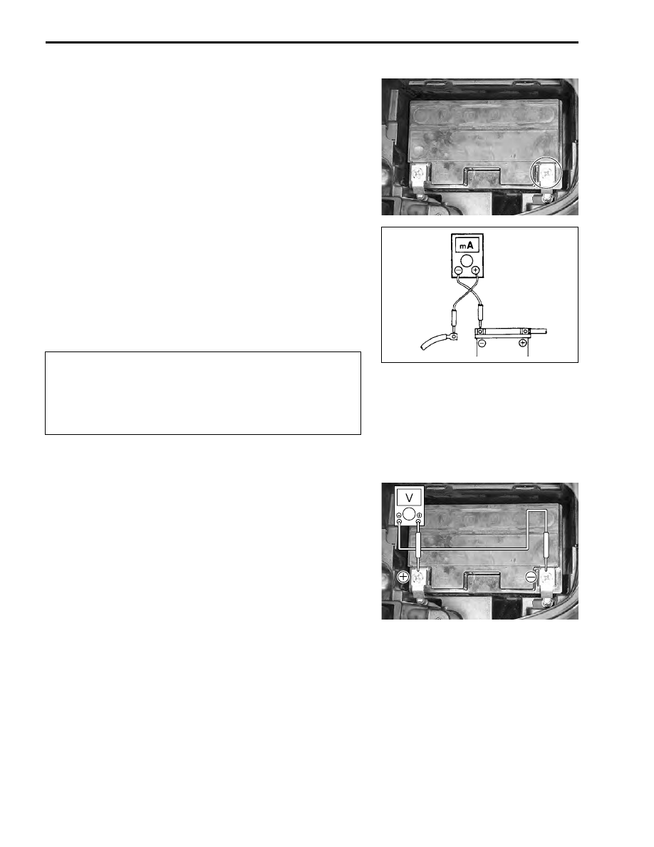
BATTERY CURRENT LEAKAGE INSPECTION

• Turn the ignition switch to the “OFF” position.
• Remove the battery cover. (

!

8-36)

• Disconnect the 


-

 battery lead wire.

Measure the current between 


-

 battery terminal and the 


-

 bat-

tery lead wire using the multi circuit tester. If the reading
exceeds the specified value, leakage is evident.

#

09900-25008: Multi circuit tester set

$

Tester knob indication: Current (

%

, 20 mA)

&

Battery current (leak): 3 mA and below

"

When checking to find the excessive current leakage, remove
the couplers and connectors, one by one, checking each part.

REGULATED VOLTAGE INSPECTION

• Remove the battery cover. (

!

8-36)

• Remove the left side leg shield. (

!

7-15)

• Start the engine, turn the ignition switch and the dimmer

switch to HI and run the engine at 5 000 r/min.

Measure the DC voltage between the 


+

 and 


-

 battery termi-

nals using the multi circuit tester.

NOTE:
When making this test, be sure that the battery is in fullycharged
condition.

If the voltage in not within the specified value, inspect the gener-
ator and regulator/rectifier. (

!

8-11)

#

09900-25008: Multi circuit tester set

'

Tester knob indication: Voltage (

%

)

&

Regulated voltage: 14.0 – 15.5 V at 5 000 r/min

* Because the current leak might be large, turn the

tester to the high range first to avoid tester damage.

* Do not turn the ignition switch to the “ON” position

when measuring current.

* Do not open the trunk during testing.

ELECTRICAL SYSTEM     8-11

GENERATOR COIL RESISTANCE INSPECTION

• Remove the front box. (

!

7-14)

• Disconnect the generator coupler 


1

.

Measure the resistance between the three lead wires.
If the resistance is not specified value, replace the stator coil
with a new one.
Also, check that the generator core is insulated.

#

09900-25008: Multi circuit tester set

(

Tester knob indication: Resistance (

)

&

Generator coil resistance : 0.2 – 0.6 

 (Yellow – Yellow)

∞ Ω

∞ Ω

∞ Ω

∞ Ω

 (Yellow – Ground)

GENERATOR NO-LOAD PERFORMANCE INSPECTION

• Remove the front box. (

!

7-14)

• Disconnect the generator coupler.
• Start the engine and run it at 5 000 r/min.

Measure the AC voltage between the lead wires of the generator
using the multi circuit tester.
If the voltage is under the specified value, replace the AC gener-
ator with a new one.

#

09900-25008: Multi circuit tester set

'

Tester knob indication: Voltage (~)

&

Generator no-load performance (when engine is cold):

55 V (AC) and more at 5 000 r/min

Y

Y

Y

Y

Y

Y

8-12     ELECTRICAL SYSTEM

REGULATOR/RECTIFIER INSPECTION

• Remove the front meter panel. (

!

7-13)

• Disconnect the regulator/rectifier couplers.

• Remove the regulator/rectifier 


1

.

Measure the voltage between the terminals using the multi cir-
cuit tester, as indicated in the table below.
If the voltage is not within the specified value, replace the regu-
lator/rectifier with a new one.

#

09900-25008: Multi circuit tester set

)

Tester knob indication: Diode test (

*

)

Unit:V

 1.4 V and more (tester’s battery voltage)

NOTE:
If the tester reads under 1.4 V when the tester probes are not
connected, replace the battery of multi circuit tester.


-

 Tester prove


+

 T

est

er p

ro

ve


A


B


C


D


E


A

0.4 – 0.7 0.4 – 0.7 0.4 – 0.7 0.5 – 1.2


B

0.4 – 0.7


C

0.4 – 0.7


D

0.4 – 0.7


E

ELECTRICAL SYSTEM     8-13

STARTER SYSTEM

TROUBLE SHOOTING

NOTE:
Make sure the fuses are not blown and the battery is fully-charged before diagnosing.

Starter motor will not run.
Step1
1) Grasp the front or rear brake lever, turn on the ignition switch with the engine stop switch in the “RUN” 

position and side-stand switch in the “ON” position.

2) Listen for a click from the starter relay when the starter button is pushed.

Is a click sound heard?

Step2
1) Check if the starter motor runs when its terminal is connected to the 


+

 battery terminal (Do not use a thin 

wire because a large amount of current flows.)
Does the starter motor run?

YES

Go to Step2.

NO

Go to Step3.

YES

• Faulty starter relay.
• Loose or disconnected starter motor lead wire.
• Loose or disconnected between starter relay and 


+

 battery terminal.

NO

Faulty starter motor.

Starter
motor

Starter
relay

Safety
relay

Starter button

Front brake switch

Rear brake switch

To ignition coil

Engine stop
switch

Turn signal/
side-stand relay

Side-stand switch

Signal fuse

lgnition fuse

lgnition switch

Main fuse

Battery


Content   ..  70  71  72  73   ..