Volkswagen e-Golf (2015 year). Manual - part 18


  Index      Volkswagen     Volkswagen e-Golf - service manual 2015 year in english


Search            copyright infringement  


Content   ..  16  17  18  19   ..


Volkswagen e-Golf (2015 year). Manual - part 18


Indicator lights 


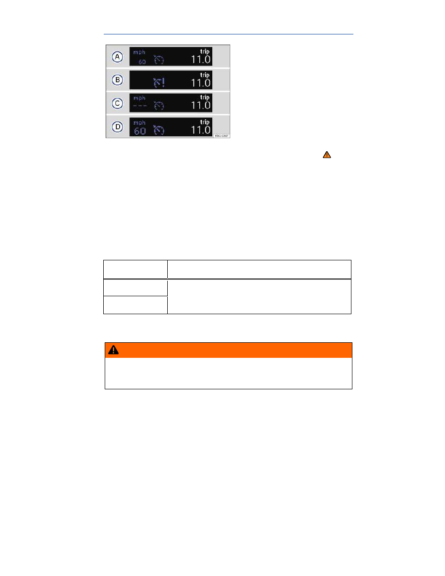
Fig. 140 In the instrument cluster display: Cruise control status indications. 

 Please first read and note the introductory information and heed the WARNINGS 


Display 

Different cruise control versions are available. The stored speed is shown in the instrument cluster 
display on some equipment versions. 

Status 

⇒ 

fig. 140


(A)


Cruise control temporarily deactivated. Stored speed displayed in a darker shade or in smaller 
numbers. 

(B)


System malfunction. See an authorized Volkswagen dealer or an authorized Volkswagen 
Service Facility. 

(C)


Cruise control activated. No speed stored in memory. 

(D)


Cruise control is active. Stored speed displayed in white or in larger numbers. 

Indicator lights 
 

Lights up  

Possible cause  


Cruise control is regulating the vehicle speed.  


When the ignition is switched on, several warning and indicator lights come on briefly for a function 
check. They go out after a few seconds. 

  WARNING 

Failure to heed warning lights and instrument cluster text messages can cause the vehicle to 
break down in traffic and result in a collision and serious personal injury. 

  Never ignore warning lights or text WARNINGS. 

  Always stop the vehicle as soon as it is safe to do so. 


  NOTICE 

Failure to heed warning lights or text WARNINGS can result in vehicle damage. 

  If the cruise control is switched on when the ignition is switched off, it may be switched on auto-

matically the next time the ignition is switched on, depending on vehicle equipment. No speed is 
stored for the cruise control. 

  The displays may vary depending on vehicle equipment. 

Cruise control operation 


Fig. 141 On the turn signal lever: Cruise control buttons and switches. 

 Please first read and note the introductory information and heed the WARNINGS 

 on 

page 284. 


In order to:  

You must: 

⇒ 

fig. 141


Result:  

Switch on 

cruise con-

trol.  

Move switch 

(1)

 on the turn signal 

lever to the   position. 

System is switched on, 

but does not regulate 

vehicle speed until a 

speed is set.  

Set cruise 

control to 

current vehi-

cle speed.  

Press button 

(2)

 on the turn signal 

lever in the area marked 

Current vehicle speed 

is set; cruise control 

helps to maintain this 

speed.  


In order to:  

You must: 

⇒ 

fig. 141


Result:  

Temporarily 

deactivate 

cruise con-

trol.  

Move switch 

(1)

 on the turn signal 

lever to the 

 position. 

OR: Depress the brake pedal.  

Cruise control is tem-

porarily deactivated. 

The speed is still 

stored in the memory.  

Resume 

speed stored 

in cruise con-

trol.  

Press button 

(2)

 on the turn signal 

lever in the area marked 

Cruise control re-

sumes speed previ-

ously set.  

Increase set 

speed (while 

cruise control 

is actively 

controlling 

vehicle 

speed).  

Press button 

(2)

 on the turn signal 

lever in the area marked 

The vehicle will accel-

erate until the new 

higher speed is 

reached and saves the 

new higher speed in 

the memory.  

Reduce set 

speed (while 

cruise control 

is actively 

controlling 

vehicle 

speed).  

Press button 

(2)

 on the turn signal 

lever in the area marked 

Cruise control will slow 

the vehicle down with-

out braking until the 

new lower speed is 

reached and saves the 

new lower speed in 

the memory.  

Switch off 

cruise con-

trol.  

Move switch 

(1)

 to the 

 posi-

tion. 

System is switched off. 

The set speed is de-

leted.  


Changing gears when cruise control is active 

The cruise control reduces acceleration as soon as the clutch pedal is pressed, and automatically 
continues to regulate the speed after a gear change. 

Driving downhill with cruise control 

If cruise control cannot maintain constant speed while driving downhill, slow the vehicle with the foot 
brake and downshift if necessary. 

Automatic deactivation 

Cruise control speed regulation is automatically deactivated or temporarily interrupted: 

  If the system detects an error that could affect the function of the cruise control. 
  If the vehicle has accelerated and goes faster than the stored speed for a longer time. 


  If the brake or clutch pedal is depressed. 
  If regulation related to driving dynamics is taking place, for example, though ESC. 
  If an airbag deploys. 
  Automatic transmission: If the selector lever is shifted from D/S to another position. 


Rear View Camera system 

 Introduction 

In this section you’ll find information about: 

Special considerations


Camera


Operation


Parking


Depending on equipment, the vehicle may be equipped with the Rear View Camera system. 

A camera in the rear hatch assists the driver while backing up or maneuvering. The camera image is 
shown together with the orientation lines projected by the system on the screen of the factory-installed 
Infotainment system. 

The Rear View Camera system may take a few seconds to bring up the camera image. 

The functions and displays of the Rear View Camera system may vary on vehicles with or without 

Park Distance Control (PDC) 

⇒  Park Distance Control (PDC)

More information: 

  Exterior views  
  Infotainment system  
  Park Distance Control  
  Parts, accessories, repairs, and modifications  

  WARNING 

The Rear View Camera system is not able to give you a clear and undistorted view of all areas 
behind the vehicle. 

  The Rear View Camera system has blind spots in which it cannot detect people and ob-

jects. 

  Always be careful and look around you when parking. The Rear View Camera system can-

not show people, animals, and objects in certain situations. Watch out for small children and 
animals in particular. 

  Due to the screen resolution or low-light conditions, the camera may not pick up thin 

posts, chain-link fences and similar fences, and other objects, or it may not show them clear-
ly. 

  The camera lens enlarges and distorts the field of vision and causes objects on the screen 

to appear altered and imprecise. 

  Always keep the camera lens clean and free of snow and ice; do not cover the lens. 


  WARNING 

The Rear View Camera system technology cannot overcome the laws of physics and the 
limits of the system. Careless or unintentional use of the Rear View Camera system may 
result in accidents and severe injuries. 

  Always adjust your speed and driving style to road, traffic, weather, and visibility condi-

tions. 

  Always keep an eye on the parking direction and the vehicle surroundings. The front of 

the vehicle swings out more than the rear of the vehicle. 

  Never pay so much attention to the graphics shown on the screen that you fail to notice 

what is going on around you. 

  Always watch for people, especially small children, animals, and objects, because the 

Rear View Camera system may not always be able to detect them. 

  The system may not be able to clearly show everything behind the vehicle. 
  Use the Rear View Camera system only when the rear hatch is completely closed. 


  NOTICE 

  The Rear View Camera system shows only two-dimensional images on the screen. Due to 

the lack of depth of field, it may be difficult or impossible to identify protruding objects or 
recesses in the road, for example.
 

  Things like thin rods, fences, posts, and trees may not be detected by the Rear View Cam-

era system and could damage the vehicle. 

Special considerations 

 Please first read and note the introductory information and heed the WARNINGS 


Requirements for parking and maneuvering with the Rear View Camera system 

Checklist 

  The rear hatch must be closed. 

  A reliable and clear image must be displayed and the camera lens must be clean 

⇒ 

fig. 142

  There must be a clear and complete view of the area behind the vehicle. 

  The rear of the vehicle must not be heavily loaded. 

  The driver must be familiar with the system. 

  The position of the camera has not changed, such as after a rear-end collision. If the position of 

the camera has changed, have the system checked by an authorized Volkswagen dealer or an au-
thorized Volkswagen Service Facility. 


Volkswagen recommends practicing parking and maneuvering with the Rear View Camera system in a 
safe place with little or no traffic or in a parking lot under good visibility and weather conditions to 
familiarize yourself with the system, the orientation lines, and the way they work. 

Rear View Camera system settings 

Depending on equipment, various settings, including brightness, contrast, and color, can be adjusted 
by tapping the function keys  -  or  + , or by moving the corresponding slider. 

To change the settings follow these instructions: 

  Park the vehicle in a safe place on a firm, level surface. 


  Apply the parking brake to help prevent the vehicle from moving 

⇒ page 244, Electronic parking 

brake

  Switch on the ignition. 

  Switch on the Infotainment system (if not already on) 

⇒ page 24, Infotainment system

  Shift into Reverse (R)

  Tap the   function key. 

  Adjust the desired settings in the menu. 

  It is not possible to open the rear hatch if the Volkswagen emblem is folded out. 

Camera 


Fig. 142 In the rear hatch: Location of the camera. 

 Please first read and note the introductory information and heed the WARNINGS 


The camera 

⇒ 

fig. 142

 (magnified view) displays only two-dimensional images. Recesses and protrud-

ing objects on the ground or protruding parts on other vehicles may be difficult or impossible to identify 
due to the lack of depth of field. 

Objects or another vehicle may seem closer or farther away on the screen than they really are. 
 

Examples of optical distortion by the camera:  

– When driving from a level surface onto an upward or downward slope.  

– When driving up or down a slope onto a level surface.  

– If the rear of the vehicle is heavily loaded.  

– When approaching protruding objects. These objects can disappear from 

the field of view when backing up.  


Cleaning the camera lens 

Keep the camera lens clean and free of snow and ice: 

  Park the vehicle in a safe place on a firm, level surface. 
  Switch on the ignition (but do not start the electric motor). 

  Apply the parking brake to help prevent the vehicle from moving 

⇒  Electronic parking brake

  Shift into Reverse (R)

  Wet the camera lens with a commercially available alcohol-based glass cleaner and clean with a 

dry cloth 

⇒ 

  Remove snow with a brush. 

  Remove ice with deicer spray 

⇒ 

  Shift the vehicle out of Reverse (R)

  Switch off the ignition. 

  NOTICE 

  Never use abrasive cleaning agents to clean the camera lens. 
  Never remove snow or ice on the camera lens with warm or hot water. This can damage the 

camera lens. 

Operation 


Fig. 143 In the Infotainment system: Rear View Camera system display (display may vary depending on 
vehicle equipment). 

 Please first read and note the introductory information and heed the WARNINGS 


Key for displays 

⇒ 

fig. 143


Symbol  

Meaning  


Depending on vehicle equipment: Switch the PDC 

display on.  


Key for displays 

⇒ 

fig. 143


Symbol  

Meaning  


Depending on vehicle equipment: Switch the PDC 

display off.  


Close the current display.  


Depending on vehicle equipment: Switch the PDC 

sound on or off.  


Setting display: brightness, contrast, color.  


Depending on vehicle equipment: Display PDC.  


Switching the camera on and off. 

The Rear View Camera system switches on and off automatically. 


Function  

Action with the ignition on  

Vehicles without Park 

Distance Control  

Vehicles with Park Dis-

tance Control  

Switch on the 

display automati-

cally:  

Shift into Reverse (R).  

Switch off the 

display automati-

cally:  

Switch off the ignition.  

OR: Drive forward faster than 6 mph (10 km/h) or for 

longer than 10 seconds.  

OR: Shift out of Reverse 

(R) and wait about 

10 seconds.  

OR: Shift out of Reverse 

(R) (display switches off 

immediately).  

Switch off the 

display manually:  

Press one of the Infotainment system buttons or tap 

the   function key on the screen.  


Function  

Action with the ignition on  

Vehicles without Park 

Distance Control  

Vehicles with Park Dis-

tance Control  


OR: Tap the function key 

.  

The PDC full screen mode 

is displayed  

Show the display 

again:  

Shift out of Reverse (R), then shift back into Reverse 

(R).  


OR: Tap the function key 

.  


Parking 


Fig. 144 On the screen: Orientation lines for the parking space behind the vehicle. A: Searching for a parking 
space, B: Backing into the parking space, C: Maneuvering. 

 Please first read and note the introductory information and heed the WARNINGS 


Key to diagram 

⇒ 

fig. 144

:  


Meaning  


Lateral green lines: Projection of the vehicle (widened somewhat) 

toward the rear. The green lines stop about 6 feet (2 meters) be-

hind the vehicle on the road.  


Key to diagram 

⇒ 

fig. 144

:  


Meaning  


Horizontal red line: Safety distance (area up to about 16 inches 

(40 cm) behind the vehicle on the road).  

(1)


Road.  

(2)


Selected parking space.  

(3)


Side lines of the selected parking space.  

(4)


Rear boundary of the parking space, such as a curb.  


All references to orientation line length apply to vehicles on a horizontal surface. 

Parking using the Rear View Camera system 
 

Step  

Action:  

1.


The requirements for parking and maneuvering with the Rear 

View Camera system must be fulfilled  

2.


Position the vehicle in front of the parking space 

(2)


⇒ 

fig. 144

 A.  

3.


Shift into Reverse (R).  

4.


Reverse slowly and steer the vehicle B so that the lateral green 

orientation lines lead into the parking space 

(2)

.  

Pay attention to the message in the display: Look! Safe to 

move? 

⇒    

5.


Align the vehicle in the parking space B so that the green orienta-

tion lines are parallel with the parking space 

(3)

.  

6.


Stop the vehicle C before (or at the very latest, when) the horizon-

tal red line reaches the rear boundary, for example, a curb 

(4)

.  


Park Distance Control (PDC) 

 Introduction 

In this section you’ll find information about: 

Operation


PDC signal chimes and displays


PDC menu


Depending on equipment, the vehicle may be equipped with the Park Distance Control system (PDC). 

The Park Distance Control (PDC) system can help the driver when backing up and parking. 

PDC uses ultrasonic sensors in the bumpers to measure the distance between the vehicle and ob-
jects. The system uses the time it takes for the ultrasonic waves to bounce back from the object to 
calculate the distance between the vehicle and an object. PDC works only at speeds up to about 5–
10 mph (10–15 km/h). 

A Declaration of Compliance with United States FCC and Industry Canada regulations is found in the 

Consumer information section of this Manual 

⇒  Consumer information

More information: 

  Exterior views  
  Infotainment system  
  Braking and parking  
  Rear View Camera system 
  Consumer information  
  Exterior care and cleaning  
  Parts, accessories, repairs, and modifications  

  WARNING 

Park Distance Control is no substitute for careful and attentive driving. Never rely completely 
on these systems for information about people and objects that might be in the way of the 
vehicle and could be struck resulting in serious personal injuries. 

  The sensors have blind spots in which they cannot detect people, animals, and objects. 
  Always be careful and look around you when parking. The sensors cannot always detect 

people, animals, and objects. Watch out for small children and animals in particular. 

  Certain types of clothing and the surfaces of certain objects do not reflect the ultrasonic 

waves that the sensors send and receive. Such objects and persons wearing such clothing 
will not be detected by PDC or will not be detected accurately. 

  Noise in the area can interfere with the signals of the Park Distance Control sensors. Un-

der certain circumstances, the system will not detect people and objects for this reason. 


  NOTICE 

  Things like thin rods, fences, trees, narrow painted vertical poles, posts, or a rear hatch that 

is opening may not be detected by the Park Distance Control sensors and could damage the 
vehicle.
 

  If you continue driving closer to an object that the Park Distance Control has already de-

tected and reported, the object may disappear from the sensor range and may no longer be 


detected. This is especially true for low or high objects. The system will no longer sound warn-
ings about these objects. Ignoring signals from the Park Distance Control system could result 
in serious damage to the vehicle.
 

  The sensors in the bumpers can be damaged or become misaligned in low speed impacts 

and parking maneuvers. Damaged or misaligned sensors cannot accurately detect or report 
objects that might be within range of the PDC system.
 

  To help make sure that the system works properly, always keep the sensors in the bumpers 

clean and free of snow and ice; do not cover the sensors with stickers or other objects. 

  When cleaning the sensors with power washers or steam cleaners, only spray the sensors 

directly for a very short time, and always keep the washer nozzle at least 4 inches (10 cm) from 
the sensors.
 

  Noise from rough roads, cobblestones, other vehicles and the surrounding area, for exam-

ple, can prevent the Park Distance Control system from accurately detecting and reporting 
people and objects that may be within range of the sensors.
 

  Aftermarket components such as bicycle racks can impair the function of the Park Distance 

Control system. 

  Volkswagen recommends practicing with the Park Distance Control system in a location or 

parking space with no traffic in order to become familiar with the system and how it works. 

Operation 


Fig. 145 In the front and rear bumpers: Park Distance Control system sensors. 


Fig. 146 In the center console: Button to switch the Park Distance Control system on or off. 

 Please first read and note the introductory information and heed the WARNINGS 


The Park Distance Control (PDC) uses ultrasonic sensors to determine the distance from the front or 
rear bumpers to an obstacle. There are 4 sensors for the PDC located in rear bumper (B) and addi-

tional sensors in the front bumper (A

⇒ 

fig. 145

 (arrows). 


The intermittent and permanent signal chimes given by the front PDC sensors are of a higher pitch 
than those given by the rear PDC sensors. This is a standard feature. 

The warning signals can be adjusted in the Infotainment system menu 

⇒  Infotainment system

Switching the Park Distance Control (PDC) system on and off 
 

In order to  

Operation (when the ignition is switched on)  

Manually activate 

PDC:  

Press the 

 button once.  

Manually deactivate 

PDC:  

Push the 

 button again.  

Manually deactivate 

the display (sound 

stays active):  

Press a function selection button on the factory-

installed Infotainment system  

OR: Tap the   function key on the screen.  

Automatically acti-

vate PDC:  

Shift into Reverse (R).  

OR: Depending on vehicle equipment, if the vehicle 

rolls backwards.  

Automatically deac-

tivate PDC:  

Shift into Park (P).  

OR: Drive forward faster than about 5–10 mph (10–

15 km/h).  

Mute the PDC vol-

ume:  

Tap the 

 function key.  

Switch from mini 

PDC display to full-

screen mode.  

Shift into Reverse (R).  

OR: Depending on vehicle equipment, if the vehicle 

rolls backwards.  

OR: Tap the mini PDC function key.  

Switch to the rear-

view camera dis-

play (if equipped):  

Shift into Reverse (R).  

OR: Tap the 

 function key.  


The indicator light in the 

 button 

⇒ 

fig. 146

 lights up and stays on as long as the feature is active. 

Automatic activation 

When the PDC is activated automatically, a mini PDC display appears on the left-hand side of the 

screen 

⇒ 

fig. 148

Automatic activation of the PDC when driving slowly towards an obstacle located in front of the vehicle 
only works when the speed falls below about 6–9 mph (10–15 km/h) for the first time. If the PDC was 
switched off using the 

 button, performing one of the following actions with the ignition switched on 

can automatically reactivate the PDC: 

  If the vehicle accelerates to a speed greater than 6–9 mph (10–15 km/h) and then drops below that 

speed again. 

  OR: If the selector lever is moved to Park (P) and then out of that position again. 
  OR: If automatic activation is turned off and on again in the Infotainment system. 

Automatic activation of the mini PDC display can be turned on or off in the Infotainment system 

⇒  

Infotainment system

When the box in the automatic activation function key is checked  , signal chimes sound from a 
distance of about 20 inches (50 cm) from the obstacle. 

  WARNING 

Never rely completely on the PDC for information about people and objects that might be in 
the way of the vehicle and could be struck by the vehicle causing serious personal injury. 

  The PDC sensors have blind spots where they cannot detect people or objects. 
  Always watch for people, especially small children and animals, because the sensors may 

not always be able to detect them. 

  If you hear a long beep of about 3 seconds when you first turn PDC on or the indicator light in 

the button starts blinking, this means there is a malfunction in the Park Distance Control system. 
Switch off the Park Distance Control system with the button and have it immediately checked by an 
authorized Volkswagen dealer or an authorized Volkswagen Service Facility. 

PDC signal chimes and displays 


Fig. 147 PDC display of the area surrounding the vehicle. 


Fig. 148 Mini PDC display of the area surrounding the vehicle. 

 Please first read and note the introductory information and heed the WARNINGS 


Key to elements in the color display  

fig. 147

 and 

fig. 148


Meaning  

(A)


Scanned area behind the vehicle.  

(B)


Scanned area in front of the vehicle.  

=


System fault in the scanned area.  


The yellow segment represents an obstacle in the ve-
hicle’s path.  


Red segment depicts an obstacle located close to the 
vehicle.  


The grey segment represents an obstacle outside of 
the vehicle's path.  


When the factory-installed Infotainment system is switched on, the areas to the front, rear, and side of 

the vehicle that are scanned by ultrasonic sensors are shown on the screen 

⇒ 

fig. 147

. The positions 

of potential obstacles are displayed relative to the vehicle 

⇒ 

Signal chimes 

When the vehicle approaches an obstacle located in the range of the ultrasonic sensors, there are 
audible signal chimes. An intermittent signal chime means that a sufficiently short distance between 
the vehicle and an obstacle is detected. The shorter the distance, the shorter the intervals between the 
chimes. The signal chime will sound continuously if the obstacle is very close. 

When there is an imminent risk of collision at the front area of the vehicle, the signal chimes beep at 
the front of the vehicle. When there is a risk of imminent collision at the rear area of the vehicle, the 
signal chimes beep at the rear of the vehicle. 


Content   ..  16  17  18  19   ..