Volkswagen Golf / Golf GTI / Golf Variant. Service manual - part 821


  Index      Volkswagen     Volkswagen Golf / Golf GTI / Golf Variant - service and repair manual 2013 year


Search            copyright infringement  


Content   ..  819  820  821  822   ..


Volkswagen Golf / Golf GTI / Golf Variant. Service manual - part 821


Greasing Bonded Rubber Bushing:
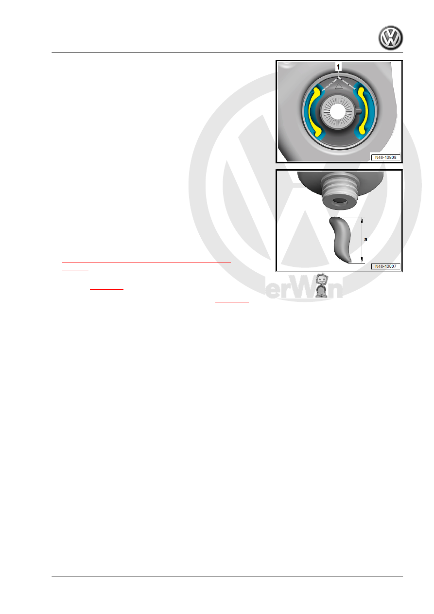
The kidney-shaped area -1- of the bonded rubber bushing must

be lubricated.
– To do so, apply grease in the kidney-shaped area -1- starting

from the top working outward.

– Use the Grease - N.052.150.00.- .

– The required quantity of grease together for both sides should

be approximately 1 cm -dimension a- as shown.

• Half of the grease quantity (approximately 0.5 cm) must be

applied per kidney-shaped area.

– The grease quantity must be applied on the top using a com‐

mercially available brush.

– The contact surfaces to the control arm must not come in con‐

tact with grease.

– Install the control arm

⇒ “4.2 Lower Control Arm, Removing and Installing”,

page 55

 .

♦ Vehicles with manual transmission, DSG transmission 0CW.

Refer to 

⇒ page 56

♦ Vehicles with DSG Transmission 0D9. Refer to 

⇒ page 59

 .

5

Wheel Bearing

⇒ “5.1 Overview - Wheel Bearing”, page 70
⇒ “5.2 Wheel Bearing Housing, Removing and Installing”,

page 70
⇒ “5.3 Wheel Bearing Unit, Removing and Installing”, page 75

5.1

Overview - Wheel Bearing

1 - Cover Plate
2 - Bolt

❑ 12 Nm

3 - Wheel Bearing Unit

❑ Removing and instal‐

ling. Refer to

⇒ “5.3 Wheel Bearing

Unit, Removing and In‐

stalling”, page 75

❑ Cannot be serviced

4 - Bolt

❑ 200 Nm + 180°
❑ Replace after removal
❑ Loosening and tighten‐

ing. Refer to

⇒ “6.4 Drive Axle Threa‐

ded Connection, Loos‐

ening and Tightening”,

page 101

5 - Wheel Bearing Housing

❑ There are different ver‐

sions. For allocation.

Refer to the Parts Cata‐

log.

❑ Removing and instal‐

ling. Refer to

⇒ “5.2 Wheel Bearing

Housing, Removing and

Installing”, page 70

6 - Bolt

❑ 70 Nm + 90°
❑ Replace after removal

7 - Drive Axle

❑ Do not let the drive axle hang down. The inner joint could be damaged if it is bent too far.
❑ Lightly coat the splines on the outer joint with assembly paste before installing the outer joint into the

wheel hub. Refer to the Parts Catalog.

5.2

Wheel Bearing Housing, Removing and

Installing

Special tools and workshop equipment required
♦ Ball Joint Splitter - 3287A-
♦ Spreader Tool - 3424-

♦ Puller - Ball Joint - T10187-
♦ Torque Wrench 1332 40-200Nm - VAG1332-
♦ Engine and Gearbox Jack - VAS6931-
♦ Digital Torque Wrench - VAG1756A-
♦ Drive Shaft Remover - T10520-
Removing
– Remove the drive axle bolt. Refer to

⇒ “6.4 Drive Axle Threaded Connection, Loosening and Tight‐

ening”, page 101

 .

Caution

The wheel bearing must not be under load when the drive axle

threaded connection on the wheel side is loose.
If the wheel bearings are under the load of the vehicle weight,

the wheel bearing will be damaged. This reduces the service

life of the wheel bearings.
The drive axle bolt may be loosened maximum 90° when the

vehicle is standing on its wheels.
Vehicles without a drive axle must not be moved, otherwise the

wheel bearing will be damaged. If a vehicle must be moved,

be sure to note the following:

♦ Install an outer joint in place of the drive axle.
♦ Tighten the outer joint to 120 Nm.

– Loosen the wheel bolts.
– Raise the vehicle.
– Remove the wheel.
– Remove the brake caliper and tie it to the vehicle body with

wire. Refer to ⇒  Brake System; Rep. Gr.  46 ; Front Brakes;

Overview - Front Brakes .

– Remove the ABS speed sensor. Refer to ⇒  Brake System;

Rep. Gr.  45 ; Sensors; Front ABS Wheel Speed Sensor -

G45- / -G47- , Removing and Installing .

– Remove the brake rotor. Refer to ⇒  Brake System; Rep. Gr. 

46 ; Overview - Front Brakes .

– Remove and free up the brake line bracket and electrical wires

from the wheel bearing housing.

– Remove the cover plate -1- from the wheel bearing housing

-arrow-.

– Loosen the nut from the tie rod end, but do not unscrew yet.

Caution

To protect the thread, screw the nut on the pin a few turns.

– Remove the tie rod from the wheel bearing housing and re‐

move the nut.

1 - -T10187-

Vehicles with Level Control System Sensor
– Remove the nut -1-.
– Remove the bracket -2- for the Left Front Level Control System

Sensor - G78- or  Right Front Level Control Sensor - G289-

from the control arm -3-.

Continuation for all Vehicles

– Loosen the nuts -arrows-.
– Remove the control arm from the ball joint.
– Remove the drive axle outer joint from the wheel hub.
If the drive axle cannot be pulled out of the wheel bearing, then

the drive axle can be pushed out of the wheel bearing using the

-T10520- .

Before using the -T10520- , make sure that the thrust piece -1- is

installed.


Content   ..  819  820  821  822   ..