Volkswagen Golf / Golf GTI / Golf Variant. Service manual - part 820


  Index      Volkswagen     Volkswagen Golf / Golf GTI / Golf Variant - service and repair manual 2013 year


Search            copyright infringement  


Content   ..  818  819  820  821   ..


Volkswagen Golf / Golf GTI / Golf Variant. Service manual - part 820


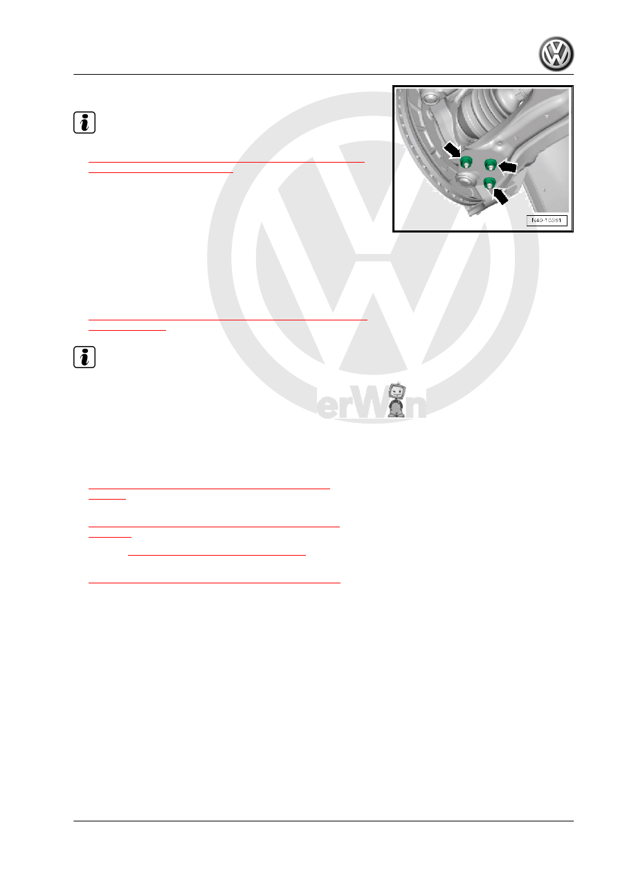
– Tighten nuts -arrows-.

Note

Tighten the nuts -arrows- in curb weight position. Refer to

⇒ “3.8.1 Wheel Bearing in Curb Weight, Lifting Vehicles with

Coil Spring, Front Axle”, page 6

 .

Make sure the ball joint boot is not damaged or twisted.

The level control system sensor lever must point toward vehi‐

cle exterior.

The thread on the vehicle level sensor must be installed into

the exterior hole in the control arm. The tab on the vehicle level

sensor bracket must lock into the inner hole in order to assure

a correct installation position.

– Install the wheel and tighten.
– Tighten drive axle bolt onto the wheel hub. Refer to

⇒ “6.4 Drive Axle Threaded Connection, Loosening and Tight‐

ening”, page 101

 .

Note

Vehicle must not be standing on its wheels when doing this, oth‐

erwise wheel bearing will be damaged.

– For vehicles with a level control system sensor, perform the

basic setting for the wheel damping electronics using the

⇒ Vehicle diagnostic tester.

Tightening Specifications
♦ Refer to

⇒ “4.1 Overview - Lower Control Arm and Ball Joint”,

page 54

♦ Refer to

⇒ “2.1 Overview - Front Level Control System Sensor”,

page 277

♦ Refer to 

⇒ “6.2 Overview - Drive Axle”, page 80

♦ Refer to

⇒ “1.1 Wheel Bolt Tightening Specifications”, page 286

4.5

Front Lower Control Arm Bonded Rub‐

ber Bushing, Replacing

Special tools and workshop equipment required
♦ Wishbone Rubber Mount Assembly Tool - T10219-
♦ Press Plate - VW402-
♦ Press Piece - Rod - VW411-
♦ Press Piece - Multiple Use - VW412-
♦ Installation Lubricant - G 294 421 A1-

Caution

This procedure contains mandatory replaceable parts. Refer

to component overview prior to starting procedure.

Mandatory Replacement Parts
♦ Nuts - Lower Control Arm to Ball Joint
♦ Bolts - Subframe to Lower Control Arm
– Remove the lower control arm. Refer to

⇒ “4.2 Lower Control Arm, Removing and Installing”,

page 55

 .

Pressing Out the Bonded Rubber Bushing
– Press out bonded rubber bushings as depicted in the illustra‐

tion.

1 - Press Piece - Rod - VW411-
2 - Wishbone Rubber Mount Assembly Tool - Tube - T10219/1-

(the opening must face the control arm)

3 - Press Plate - VW402-

Installing the Bonded Rubber Bushing
– Align the bonded rubber bushing -1- with the control arm -2-.
The grooves -3- must point to the control arm -2- as shown.
– Apply Installation Lubricant - G 294 421 A1- onto the outside

of the bonded rubber bushing.

– Install the bonded rubber bushing as illustrated.
1 - Wishbone Rubber Mount Assembly Tool-Drift - T10219/2-
2 - Bonded rubber bushing
3 - Wishbone Rubber Mount Assembly Tool - Tube - T10219/1-

(the opening must face the control arm)

4 - Press Plate - VW402-

Note

The bonded rubber bushing will be crooked for a short time at the

beginning of the installation. Later it will straighten out. It will not

be necessary to guide it.

– Install the bonded rubber bushing until the core -1- and the

transverse link hole -2- are at the same height.

– Press back bearing slightly in control arm.
1 - Press Piece - Multiple Use - VW412-
2 - Wishbone Rubber Mount Assembly Tool -Tube - T10219/1-
3 - Press Plate - VW402-

Dimensions -a and b- must be identical.
– Install the lower control arm. Refer to

⇒ “4.2 Lower Control Arm, Removing and Installing”,

page 55

 .

4.6

Lower Control Arm Rear Bonded Rub‐

ber Bushing, Replacing

Special tools and workshop equipment required
♦ Bearing Installer - Wheel Bearing - 3345-
♦ Bearing Installer - Multiple Use - 3348-
♦ Press Plate - VW401-
♦ Press Piece - Rod - VW411-
♦ Press Piece - Multiple Use - VW412-
♦ Bearing Installer - Ball Joint/Bushing/Bearing - VW459-
– Remove the control arm. Refer to

⇒ “4.2 Lower Control Arm, Removing and Installing”,

page 55

 .

♦ Vehicles with manual transmission, DSG transmission 0CW.

Refer to

⇒ “4.2.1 Lower Control Arm, Removing and Installing, Vehicles

with Manual Transmission, DSG Transmission 0CW”,

page 55

♦ Vehicles with DSG Transmission 0D9. Refer to

⇒ “4.2.2 Lower Control Arm, Removing and Installing, Vehicles

with DSG Transmission 0D9”, page 57

 .

Bonded Rubber Bushing, Pressing Out
– Press out the bonded rubber bushings as shown.
1 - -VW411-
2 - -3348-
3 - Control Arm
4 - -3345-
5 - -VW401-

Bonded Rubber Bushing Installed Position
• The stamped arrow points between the markings -arrows A-

in the control arm.

• The cam -arrow B- must always point to the outside of the

vehicle. The open kidney-shape points to the vehicle center.

Bonded Rubber Bushing, Pressing In
– Install the bonded rubber bushing as shown.
1 - -VW412-
2 - -VW459/2- , the inner offset in the sleeve -arrow- points

downward

3 - Control Arm
4 - -3345-
5 - -VW401-

Note

Install the bonded rubber bushing far enough until the -3345-

contacts the control arm.


Content   ..  818  819  820  821   ..