Volkswagen Golf / Golf GTI / Golf Variant. Service manual - part 810


  Index      Volkswagen     Volkswagen Golf / Golf GTI / Golf Variant - service and repair manual 2013 year


Search            copyright infringement  


Content   ..  808  809  810  811   ..


Volkswagen Golf / Golf GTI / Golf Variant. Service manual - part 810


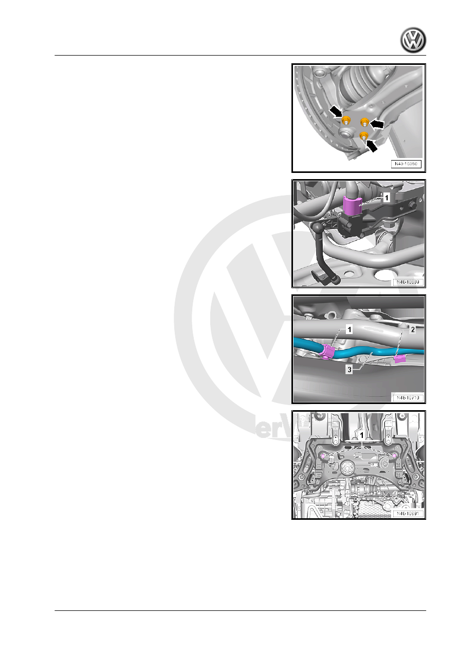
– Remove the nuts -arrows- on the left and right side of the ve‐

hicle.

Vehicles with Level Control System Sensor
– Disconnect the connector -1- from the Left Front Level Control

System Sensor - G78- or  Right Front Level Control Sensor -

G289- .

Continuation for all Vehicles

– Remove the clips -1 and 2- for the wiring harness -3- from the

subframe and the steering gear.

– Remove the steering gear bolts -1-.
– Pry the steering gear out of the subframe alignment sleeves.

– Place the -VAS6931- -1- under the subframe.
– Secure the subframe (refer to

⇒ “2.2 Subframe, Securing”, page 17

 ) and lower it approxi‐

mately 10 cm.

– Remove the expanding clip -arrow-.
– Lower the subframe using the -VAS6931- .

– Secure the subframe on the -VAS6931- .
– Secure the steering gear on the body.
Installing
Install in reverse order of removal while noting the following:

– Tighten nuts -arrows-.

Note

Tighten the nuts -arrows- in curb weight position. Refer to

⇒ “3.8.1 Wheel Bearing in Curb Weight, Lifting Vehicles with Coil

Spring, Front Axle”, page 6

 .

– For vehicles with a level control system sensor, perform the

basic setting for the wheel damping electronics using the

⇒ Vehicle diagnostic tester.

Tightening Specifications
♦ Refer to 

⇒ “2.1 Overview - Subframe”, page 16

♦ Refer to 

⇒ “2.1 Overview - Steering Column”, page 338

♦ Pendulum support bolts. Refer to ⇒  Rep. Gr.  10 ; Subframe

Mount; Overview - Subframe Mount .

♦ Noise insulation bolts. Refer to ⇒  Body Exterior; Rep. Gr.  66 ;

Noise Insulation; Overview - Noise Insulation .

♦ Exhaust system to subframe. Refer to ⇒  Rep. Gr.  26 ; Exhaust

Pipes/Mufflers; Overview - Muffler .


If the steering wheel is still crooked after using the -T10486/1-

then an axle alignment is necessary. In this case the record it in

the vehicles axle alignment log.

2.5

Subframe with Steering Gear, Remov‐

ing and Installing

Special tools and workshop equipment required
♦ Puller - Ball Joint - T10187-
♦ Torque Wrench 1332 40-200Nm - VAG1332-
Removing
– Turn the steering wheel in the straight position and remove the

ignition key so that the steering wheel lock engages.

Vehicles with “Keyless Access” Keyless Locking and Starting

System
– Switch the ignition off and open the driver door so the steering

wheel lock engages.

Continuation for all Vehicles.
– Remove the bolts -1- and fold the footwell trim panel -2- in the

direction of the -arrow- into the vehicle interior.

– Remove the bolt -1- from the universal joint -2-. Then remove

the universal joint in direction of -arrow-.

Caution

If the universal joint is separated from the steering gear, the

following work cannot be performed:

♦ Connect the battery.
♦ Switching on the ignition
♦ Turning the steering gear
♦ Turning the steering column.

These points must be observed since performing these actions

could cause irreparable damage.

– Loosen the wheel bolts.
– Raise the vehicle.
– Remove the wheels.
– Remove the lower noise insulation. Refer to ⇒  Body Exterior;

Rep. Gr.  66 ; Noise Insulation; Overview - Noise Insulation .

– Remove the exhaust system bracket from the subframe

-arrows-.

– Remove the pendulum support bolts -1-.


Content   ..  808  809  810  811   ..