Volkswagen Golf / Golf GTI / Golf Variant. Service manual - part 809


  Index      Volkswagen     Volkswagen Golf / Golf GTI / Golf Variant - service and repair manual 2013 year


Search            copyright infringement  


Content   ..  807  808  809  810   ..


Volkswagen Golf / Golf GTI / Golf Variant. Service manual - part 809


♦ Engine and Gearbox Jack - VAS6931-
♦ Locating Pins - T10486/1-
♦ Vehicle Diagnostic Tester

Caution

This procedure contains mandatory replaceable parts. Refer

to component overview prior to starting procedure.

Mandatory Replacement Parts
♦ Bolt - Universal Joint to Steering Gear
♦ Bolts - Pendulum Support to Transmission
♦ Nut - Coupling Rod to Stabilizer Bar
Removing
– Turn the steering wheel to the straight-ahead position and re‐

move the ignition key so that the steering wheel lock engages.

Vehicle with “Keyless Access” Keyless Locking and Starting Sys‐

tem
– Switch the ignition off and open the driver door so the steering

wheel lock locks.

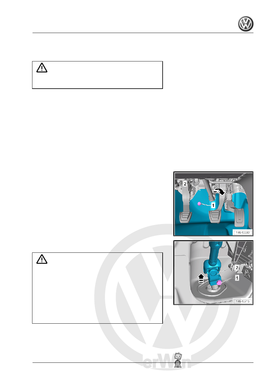
– Remove the bolt -1- and fold the footwell trim panel -2- in di‐

rection of -arrow- into the vehicle interior.

– Remove the bolt -1- from the universal joint -2-. Then remove

the universal joint in direction of -arrow-.

Caution

If the universal joint is separated from the steering gear, the

following work cannot be performed:

♦ Connect the battery.
♦ Switch on the ignition.
♦ Turning the steering gear
♦ Turning the steering column

These  points  must  be  observed,  because  otherwise  it  can

cause irreparable damage.

– Remove the lower noise insulation. Refer to ⇒  Body Exterior;

Rep. Gr.  66 ; Noise Insulation; Overview - Noise Insulation .

– Remove the exhaust system bracket from the subframe

-arrows-.

– Remove the pendulum support bolts -1-.

– Remove the hex nut -1- from the right and left coupling rod

-3-.

– Remove the coupling rod -3- from the stabilizer bar -2- on the

left and right sides.

Vehicles with a Vehicle Level Sensor
– Disconnect the connector -1- from the Left Front Level Control

System Sensor - G78- or Right Front Level Control Sensor -

G289- .

Continuation for All Vehicles

– Place the Engine and Gearbox Jack - VAS6931- -1- under the

subframe.

– Secure the subframe and lower it approximately 10 cm. Refer

to 

⇒ “2.2 Subframe, Securing”, page 17

 .

Note

Be careful not to overstretch the wire for the steering and the Oil

Level Thermal Sensor - G266- .

Installing
Install in reverse order of removal. Note the following:

Note

Coat the seal on the steering gear with lubricant such as soft

soap before installing the steering gear.

After attaching the steering gear to universal joint, make sure

that seal on steering gear is positioned to mounting plate with‐

out kinks. The opening to foot well must be sealed correctly.

Ingress of water and/or noises may be the result.

Make sure sealing surfaces are clean.

– Remove the Locating Pins - T10486/1- . Refer to 

⇒ page 20

 .

– For vehicles with a vehicle level sensor, perform the basic set‐

ting for the wheel damping electronics. Refer to Vehicle Diag‐

nostic Tester .

Tightening Specifications
♦ Refer to 

⇒ “2.1 Overview - Subframe”, page 16

♦ Refer to 

⇒ “3.1 Overview - Steering Gear”, page 350

♦ Refer to 

⇒ “2.1 Overview - Steering Column”, page 338

♦ Refer to ⇒  Engine Mechanical, Fuel Injection and Ignition;

Rep. Gr.  10 ; Subframe Mount; Overview - Subframe Mount

or ⇒  Engine Mechanical, Fuel Injection and Glow Plug; Rep.

Gr.  10 ; Subframe Mount; Overview - Subframe Mount .

♦ Refer to ⇒  Body Exterior; Rep. Gr.  66 ; Noise Insulation;

Overview - Noise Insulation .

♦ Refer to ⇒  Engine Mechanical, Fuel Injection and Ignition;

Rep. Gr.  26 ; Exhaust Pipes/Mufflers; Overview - Muffler or

⇒  Engine Mechanical, Fuel Injection and Glow Plug; Rep. Gr. 

26 ; Exhaust Pipes/Mufflers; Overview - Muffler .

If the steering wheel is found to be crooked during a road test

despite using the Locating Pins - T10486/1- , then an axle align‐

ment is necessary. In this case, put the axle alignment log in the

vehicle files.

2.4

Subframe without Steering Gear, Re‐

moving and Installing

Special tools and workshop equipment required
♦ Torque Wrench 1332 40-200Nm - VAG1332-
♦ Locating Pins - T10486/1-
♦ Engine and Gearbox Jack - VAS6931-

Removing

Note

Subframe is removed together with control arms.

– Loosen the wheel bolts.
– Raise the vehicle.
– Remove the wheels.
– Remove the lower noise insulation. Refer to ⇒  Body Exterior;

Rep. Gr.  66 ; Noise Insulation; Overview - Noise Insulation .

– Remove the exhaust system bracket from the subframe

-arrows-.

– Remove the pendulum support bolts -1-.

– Remove the hex nut -1- from the right and left coupling rod

-3-.

– Remove the coupling rod -3- from the stabilizer bar -2- on the

left and right sides.


Content   ..  807  808  809  810   ..