Volkswagen Golf / Golf GTI / Golf Variant. Service manual - part 779


  Index      Volkswagen     Volkswagen Golf / Golf GTI / Golf Variant - service and repair manual 2013 year


Search            copyright infringement  


Content   ..  777  778  779  780   ..


Volkswagen Golf / Golf GTI / Golf Variant. Service manual - part 779


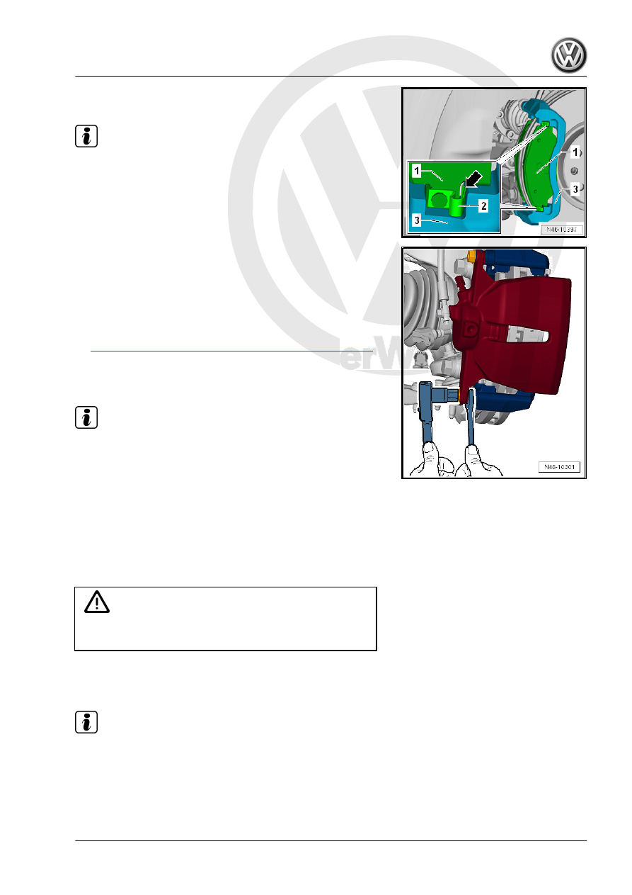
– Place the brake pads -1- and the springs -2- into the opening

in the brake carrier -3-.

Note

After installing the brake pads -arrow-, check the seating of all the

springs -2-.

– Place the brake caliper carefully on the brake carrier.

– Counterhold the guide pins and attach the brake caliper to the

brake carrier with new self-locking screws.

– Connect the brake pad wear indicator connector.
– Install the wheels.
Tightening Specification
♦ Refer to

⇒ “1.1.1 Overview - Front Brakes (PC57 and C60)”, page 43

♦ Wheel bolts. Refer to ⇒  Suspension, Wheels, Steering; Rep.

Gr.  44 ; Wheels and Tires; Wheel Bolt Tightening Specifica‐

tions .

Note

After replacing brake pads, depress brake pedal firmly several

times with vehicle stationary so that the brake pads are prop‐

erly seated in their normal operating position.

Check brake fluid level after replacing brake pad.

1.3

Brake Caliper, Removing and Installing

Special tools and workshop equipment required
♦ Torque Wrench 1331 5-50Nm - VAG1331-
♦ Brake Pedal Actuator - VAG1869/2- .

Caution

This procedure contains mandatory replaceable parts. Refer

to component overview prior to starting procedure.

Mandatory Replacement Parts
♦ Hex Bolt, Self-Locking - Brake caliper to brake carrier

Note

Work procedure applies only for replacing or when performing

subsequent service work on brake caliper.

Removing
– Remove the wheels.
– Disconnect the brake pad wear indicator connector.
– Attach the bleeder bottle bleed hose -1- to the brake caliper

bleed valve.

– Open the bleeder valve.

– Install the Brake Pedal Actuator - VAG1869/2- .
– Close the bleed valve and remove the bleeder bottle.
– Remove the brake hose.

– Counterhold the guide pins and remove both bolts from the

brake caliper.

– Remove the brake caliper from the brake carrier.
Installing
• Piston is pressed back.
• Both brake pads and their springs fit into the opening in the

brake carrier.

– Place the brake caliper carefully on the brake carrier.
– Counterhold the guide pins and attach the brake caliper to the

brake carrier with new self-locking screws.

– Attach the brake hose to the brake caliper.
– Remove the Brake Pedal Actuator - VAG1869/2- .
– Connect the brake pad wear indicator connector.
– Bleed the brake system. Refer to

⇒ “6 Hydraulic System”, page 132

 .

– Install the wheels.
– Before moving the vehicle, press the brake pedal firmly sev‐

eral times to seat the brake pads correctly in their operating

position.

– Check brake fluid level.
Tightening Specification
♦ Refer to

⇒ “1.1.1 Overview - Front Brakes (PC57 and C60)”, page 43

♦ Refer to 

⇒ “1.1 Overview - Front Brake Caliper”, page 97

♦ Refer to ⇒  Suspension, Wheels, Steering; Rep. Gr.  44 ;

Wheels and Tires; Wheel Bolt Tightening Specifications .

Note

With the vehicle stationary, firmly press the brake pedal sev‐

eral times so that the brake pads in the operating condition

properly sit in their respective position.

Check the brake fluid level.

1.4

Brake Carrier, Removing and Installing

Special tools and workshop equipment required
♦ Torque Wrench 1331 5-50Nm - VAG1331-
♦ Torque Wrench 1332 40-200Nm - VAG1332-
♦ Piston Resetting Tool - T10145-
Removing

Note

When removing, mark brake pads that will be used again. In‐

stall in the same position, otherwise braking effect will be

uneven.

Do not open the brake hydraulic system when removing!

– Loosen the wheel bolts.
– Raise the vehicle.
– Remove the wheel.
– Remove brake pads. Refer to

⇒ “1.2 Brake Pads, Removing and Installing”, page 45

 .

– Remove brake caliper and secure with wire so that the weight

of the brake caliper does not burden or damage the brake

hose.

– Unscrew the threaded connection -arrows- from the cover

plate -1-.

– Remove the brake carrier -1-.
Cleaning

WARNING

Do not blow brake system using compressed air, the dust pro‐

duced is harmful to health!

Note

Clean brake caliper with mineral spirits exclusively.

Installing
Install in reverse order of removal. Note the following:

Note

Before installing, clean carefully and check for wear and damage.

– Thoroughly clean the contact surfaces on the brake carrier for

the brake pads and remove any corrosion.

If using the brake pads again, install the marked pads in the same

location.

Note

Before pushing back the piston, extract some of the brake fluid

out of the brake fluid reservoir using a bleeder bottle. Otherwise,

especially if reservoir has been topped off, fluid will overflow and

cause damage.

– Before moving the vehicle, press the brake pedal firmly sev‐

eral times to seat the brake pads correctly in their operating

position.

– Check brake fluid level.
Tightening Specification
♦ Refer to

⇒ “1.1.1 Overview - Front Brakes (PC57 and C60)”, page 43

♦ Refer to 

⇒ “1.1 Overview - Front Brake Caliper”, page 97

♦ Refer to ⇒  Suspension, Wheels, Steering; Rep. Gr.  44 ;

Wheels and Tires; Wheel Bolt Tightening Specifications .


Content   ..  777  778  779  780   ..