Volkswagen Golf / Golf GTI / Golf Variant. Service manual - part 744


  Index      Volkswagen     Volkswagen Golf / Golf GTI / Golf Variant - service and repair manual 2013 year


Search            copyright infringement  


Content   ..  742  743  744  745   ..


Volkswagen Golf / Golf GTI / Golf Variant. Service manual - part 744


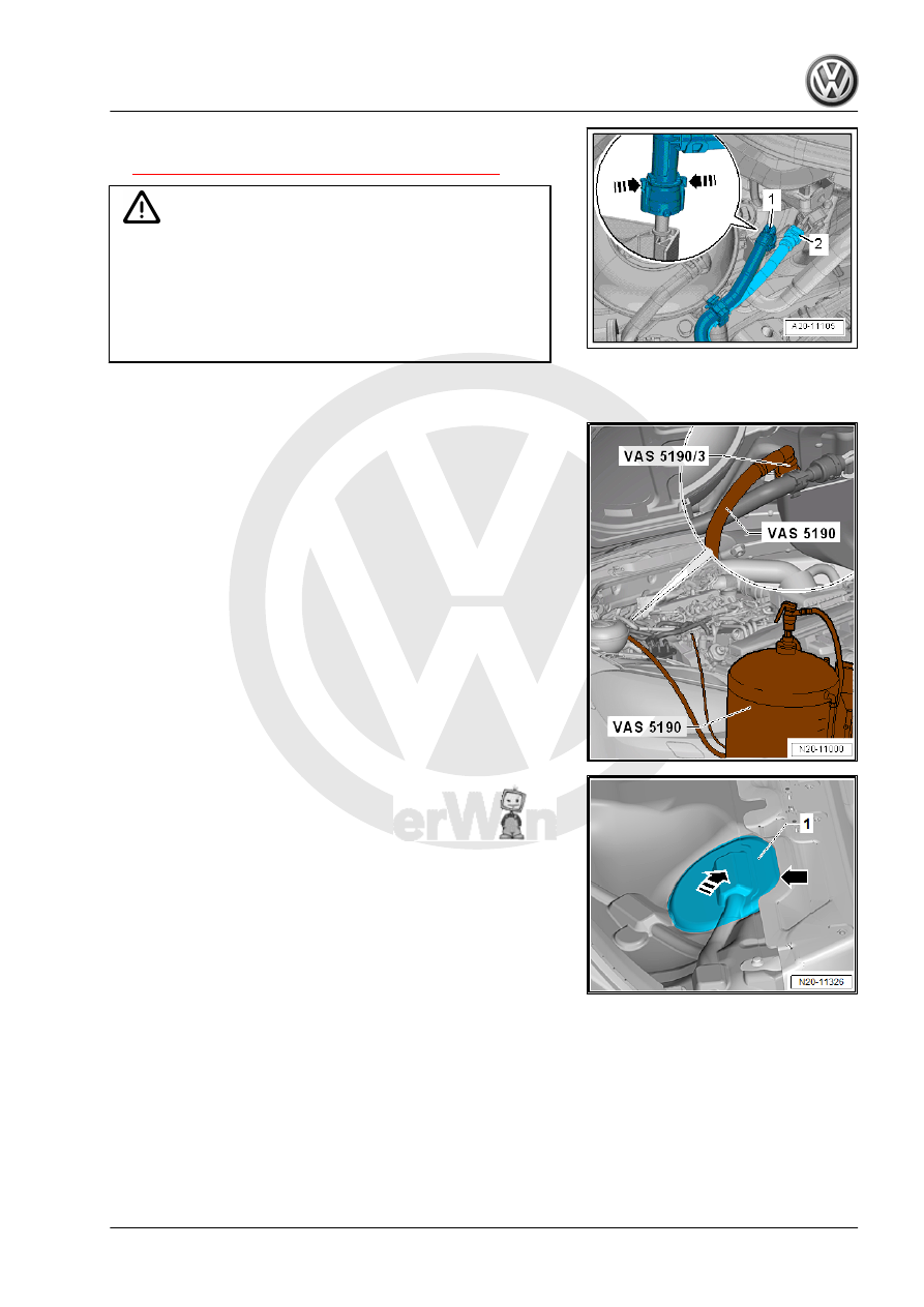
– Disconnect the fuel supply line -1-. Disconnect the connector

couplings. Refer to

⇒ “4.1 Connector Couplings, Disconnecting”, page 62

 .

WARNING

The fuel line is under pressure.
Fuel poses a risk of injury to the eyes and skin.
Wear protective eyewear and protective clothing to avoid injury

and contact with skin. Place a cleaning cloth around the con‐

nection  point  before  loosening  hose  connections.  Carefully

open the connection point to release the pressure.

– Collect leaking fuel with a cleaning cloth.

– Connect the Fuel Extraction Unit - VAS 5190- and Fuel Ex‐

traction - Adapter 3 - VAS5190 /3- to the fuel supply line.

– Attach the ground wire of the Fuel Extractor Unit to a bare area

on the body.

Golf Sportsvan:
– Remove the right rear seat. Refer to ⇒  Body Interior; Rep. Gr. 

72 ; Rear Seats; Bench Seat / Single Seat, Removing and In‐

stalling .

– Partially loosen the cover -1- in the carpet at the separating

line -arrow-.

– Do not separate the cover completely from the carpet so that

later it will be installed correctly.

– Only loosen so far that the cover can be folded up.
– Fold up the cover in the -direction of the arrow-.
Golf and Golf wagon:
– Remove the rear bench seat. Refer to ⇒  Body Interior; Rep.

Gr.  72 ; Rear Seats; Bench Seat / Single Seats, Removing

and Installing .

Continuation for All Vehicles:
– Unclip the sealing flange cover -1- at the tabs -arrows- using

the Trim Removal Wedge - 3409- .

– Unclip the grommet -1- downward out of the cover -2-.
– Guide the cover -2- on the wiring harness -3- toward the rear.

– Release and disconnect the connector -arrow-.

– Connect the Vehicle Diagnostic Tester - Test Adapter - 5 Pin

- VAS5565- to the connector and to the fuel delivery unit.

– Connect the Injection Rate Comparison Meter Kit - Remote

Cable - VAG1348/3A- to the Vehicle Diagnostic Tester - Test

Adapter - 5 Pin - VAS5565- and battery positive (+).

Note

This step allows the fuel pump to run when the engine is not run‐

ning.

– Open the fuel filler door unit -2-.
– Clean the area around the fuel filler neck.
– Remove the cap -1- for the fuel filler neck.
– Press the Injection Rate Comparison Meter Kit - Remote Ca‐

ble - VAG1348/3A- and the shut-off valve on the Fuel Extractor

Unit - VAS 5190- until the fuel tank is empty.

Note

Risk of damaging/destroying the Transfer Fuel Pump - G6- when

the fuel tank is empty.

1.3.3

Fuel Tank, Draining When More than 

3

/

4 Full

Special tools and workshop equipment required
♦ Fuel Extractor VAS5190A - VAS5190-
♦ Fuel Extraction Unit - VAS5190A- (not illustrated) for E 85 -

fuel.

Note

Use only the Fuel Extractor Unit - VAS5190A- when extracting E

85 - fuel!

– Pay attention to all safety precautions. Refer to

⇒ “1 Safety Precautions”, page 1

 .

– Follow the guidelines for clean working conditions. Refer to

⇒ “3.1 Parking/Auxiliary Heater and Fuel System Clean Work‐

ing Conditions”, page 4

 .

– Mark the hose -arrow- at the distance -a- from the end of the

suction hose on the -VAS5190- .

– Use insulating tape.

Rear Axle

Distance a in mm

Vehicles with multi-link rear axle

945 mm

Vehicles with Torsion Beam Rear Suspension

1010 mm

– Open the fuel filler door unit -2-.
– Clean the area around the fuel filler neck.
– Remove the cap -1- for the fuel filler neck.
– Attach the ground wire from the -VAS5190A- to a bare area

on the body.

– Slide the suction hose from the -VAS5190A- into the fuel tank

until the previously made mark -arrow- meets the filler neck

-2-.

– Drain the fuel tank as much as possible through the filler neck.

Note

A valve -1- is located in the fuel tank on the lower end of the

filler neck. It must not be damaged by the suction hose. Only

slide the hose in as far as the mark that was made earlier

-arrow-.

Do not use force to remove the suction hose it if gets stuck on

the check valve.

In this case, remove the fuel delivery unit and manually hold

the check valve open. When doing this, make sure the arm

does not come in contact with the fuel.

– Carefully remove the suction hose.

Note

When no more fuel can be extracted, the fuel tank is only

emptied enough so that the sensor flange can be opened

safely.

When working on the fuel delivery unit or on the Fuel Gauge

Sensor , proceed as follows. Refer to

⇒ “1.3.4 Fuel Tank, Draining When Less Than 3/4 Full”, page

44

 .

1.3.4

Fuel Tank, Draining When Less Than 

3

/

4 Full

Special tools and workshop equipment required
♦ Trim Removal Wedge - 3409-
♦ Fuel Extractor VAS5190A - VAS5190-
♦ Fuel Extraction Unit - VAS5190A- (not illustrated) for E 85 -

fuel.

♦ Wrench - Fuel Sending Unit - T10202-
♦ Torque Wrench 1332 40-200Nm - VAG1332-


Content   ..  742  743  744  745   ..