Volkswagen Golf / Golf GTI / Golf Variant. Service manual - part 742


  Index      Volkswagen     Volkswagen Golf / Golf GTI / Golf Variant - service and repair manual 2013 year


Search            copyright infringement  


Content   ..  740  741  742  743   ..


Volkswagen Golf / Golf GTI / Golf Variant. Service manual - part 742


Continuation for All Vehicles:
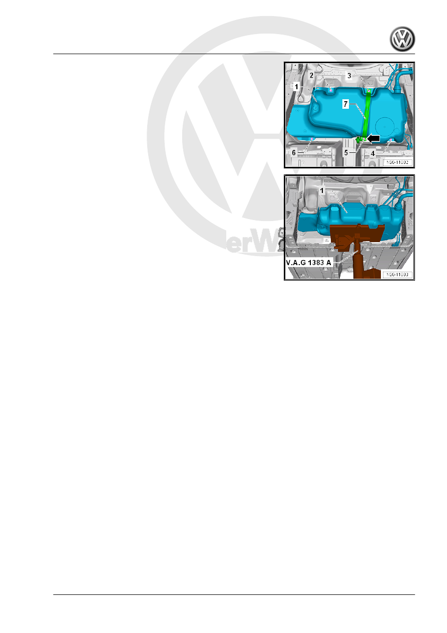
– Remove the bolt -5-.
– Remove the bracket for the exhaust system -arrow-.
– Remove the bolt -3- and remove the mounting strap -7-.

– Place the -VAS6931- under the fuel tank -1- to support it as

illustrated.

– Remove the bolts -2, 4 and 6-.

Note

To improve clarity, the fuel tank is shown without the -

VAS6931- .

A second technician is required to remove the fuel tank.

– Lower the fuel tank -1- using the -VAS6931- .
Installing
Install in reverse order of removal. Note the following:

Note

Disconnect the connector couplings. Refer to

⇒ “4.1 Connector Couplings, Disconnecting”, page 62

 .

– If equipped, make sure the Metering Pump - V54- is seated

securely.

– Make sure the vent and fuel lines are routed without kinks.
– Make sure to guide the fuel filler neck correctly into the opening

in the body.

– Position the fuel tank together with the mounting strap on the

underbody using the -VAS6931- .

– Note the location of the mounting strap.
– Make sure the supply, return and breather lines are still clipped

to the fuel tank after the fuel tank has been installed.

– Note the correct installation location for the exhaust system

bracket. Refer to ⇒  Rep. Gr.  26 ; Exhaust Pipes/Muffler;

Overview - Muffler .

– Make sure the line connections are secure.
– Check the fit by pulling on it.

– Check the ground cable for traces of oxidation on the connec‐

tors. Remove any oxidation if necessary.

– Check the installation position of the ground connection.
• The connector -2- must be securely attached to the metal ring

-3-.

• The contact -1- must be engaged in the fuel tank -4- and se‐

cured with the spacer -5-.

– Check the metal ring connection on the fuel filler neck to a bare

area on the body with an ohmmeter.

• Specified value is approximately 0 ohm.
• If the specified values is incorrect, then there is a risk of ex‐

plosion due to electrostatic discharge.

– Fill at least five liters of fuel in the fuel tank.

WARNING

There is a risk of the fuel tank exploding! After installing a new

or completely emptied fuel tank, fill it immediately with a mini‐

mum of five liters of fuel. Do not allow the fuel pump to run when

the fuel tank is completely empty.

Tightening Specifications
♦ Refer to

⇒ “1.1.2 Overview - Fuel Tank, Vehicles with FWD and Torsion

Beam Rear Suspension”, page 8

♦ Refer to ⇒  Body Interior; Rep. Gr.  72 ; Rear Seats; Bench

Seat / Single Seats, Removing and Installing .

♦ Refer to ⇒  Rep. Gr.  26 ; Exhaust Pipes/Mufflers; Overview -

Muffler .

♦ Refer to ⇒  Body Exterior; Rep. Gr.  55 ; Fuel Filler Door Unit;

Fuel Filler Door Unit, Removing and Installing .

♦ Refer to ⇒  Suspension, Wheels and Steering; Rep. Gr.  42 ;

Rear Axle; Rear Axle, Removing and Installing .

♦ Refer to ⇒  Body Exterior; Rep. Gr.  66 ; Underbody Trim Pan‐

el .

1.3

Fuel Tank, Draining

⇒ “1.3.1 Fuel Tank, Draining with Fuel Pump Installed”,

page 35

 .

⇒ “1.3.2 Fuel Tank, Emptying with Fuel Pump Installed, Vehicles

with Engine Code CWVA”, page 38
⇒ “1.3.3 Fuel Tank, Draining When More than 3/4 Full”,

page 43
⇒ “1.3.4 Fuel Tank, Draining When Less Than 3/4 Full”,

page 44
⇒ “1.3.5 Fuel Tank less than 3/4 Full, Emptying, Vehicles with

Engine Code CWVA”, page 47

1.3.1

Fuel Tank, Draining with Fuel Pump In‐

stalled

Special tools and workshop equipment required
♦ Trim Removal Wedge - 3409-

♦ Connector Test Set - VAG1594D-
♦ Injection Rate Comparison Meter Kit - Remote Cable -

VAG1348/3A-

♦ Vehicle Diagnostic Tester - Test Adapter - 5 Pin - VAS5565-
♦ Fuel Extractor VAS5190A - VAS5190-
♦ Fuel Extraction Unit - VAS5190A- (not illustrated) for E 85 -

fuel.

♦ Fuel Extraction Adapter - VAS5190-

Note

Use only the -VAS5190A- when extracting E 85 - fuel!

Note

If the -VAS5190- has a suction hose with a mounted tip, then re‐

place this with one that has a tip which screws on.

– Observe the safety instructions. Refer to

⇒ “1 Safety Precautions”, page 1

 .

– Follow the guidelines for clean working conditions. Refer to

⇒ “3.1 Parking/Auxiliary Heater and Fuel System Clean Work‐

ing Conditions”, page 4

 .

– Disconnect the fuel supply line -1-. Disconnect the connector

couplings. Refer to

⇒ “4.1 Connector Couplings, Disconnecting”, page 62

 .

WARNING

The fuel line is under pressure.
Fuel poses a risk of injury to the eyes and skin.
Wear protective eyewear and protective clothing to avoid injury

and contact with skin. Place a cleaning cloth around the con‐

nection  point  before  loosening  hose  connections.  Carefully

open the connection point to release the pressure.

– Collect leaking fuel with a cleaning cloth.


Content   ..  740  741  742  743   ..