Volkswagen Golf / Golf GTI / Golf Variant. Service manual - part 728
2
Emissions Control
⇒ “2.1 Overview - Emissions Control”, page 348
.
⇒ “2.2 Catalytic Converter, Removing and Installing”, page 349
2.1
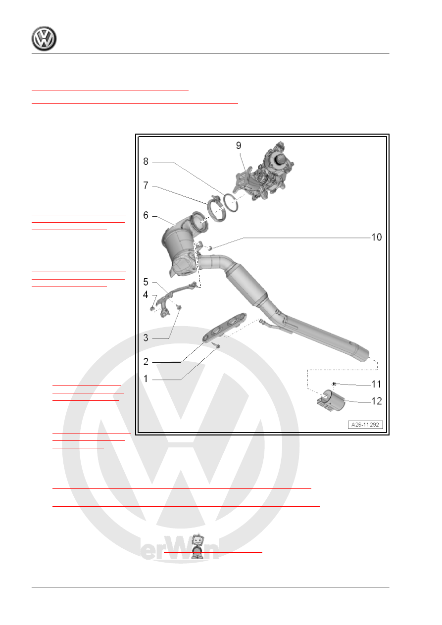
Overview - Emissions Control
1 - Bolt
❑ 20 Nm
2 - Bracket
❑ Replace if damaged
3 - Bolt
Tightening specification and
sequence. Refer to
⇒ Fig. ““Catalytic Converter -
.
4 - Nut
Tightening specification and
sequence. Refer to
⇒ Fig. ““Catalytic Converter -
.
5 - Bracket
❑ For catalytic converter
6 - Catalytic Converter
❑ With front exhaust pipe
❑ Protect catalytic con‐
verter from shocks and
impact stress
❑ Removing and instal‐
ling. Refer to
.
❑ Align the exhaust sys‐
tem free of tension. Re‐
fer to
7 - Screw-Type Clamp
❑ Replace after removing
❑ Installed position. Refer to
⇒ Fig. ““Installed Location of the Catalytic Converter Screw Clamp”“ , page 349
❑ Tightening specification and sequence. Refer to
⇒ Fig. ““Catalytic Converter - Tightening Specification and Sequence”“ , page 349
.
8 - Seal
❑ Replace after removing
9 - Turbocharger