Volkswagen Golf / Golf GTI / Golf Variant. Service manual - part 726


  Index      Volkswagen     Volkswagen Golf / Golf GTI / Golf Variant - service and repair manual 2013 year


Search            copyright infringement  


Content   ..  724  725  726  727   ..


Volkswagen Golf / Golf GTI / Golf Variant. Service manual - part 726


1.1.2

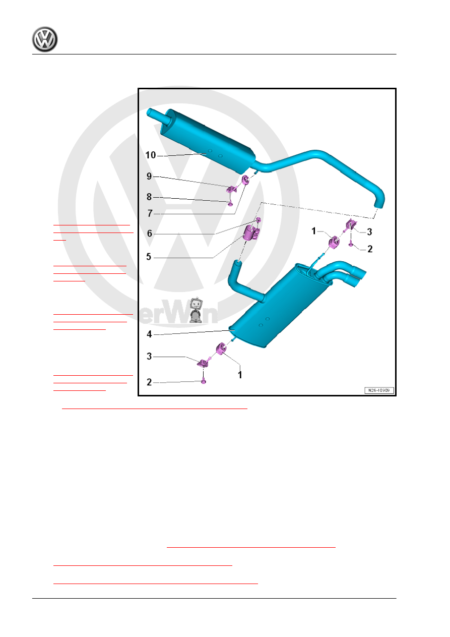
Overview - Muffler, Golf with 1.8L Engine

1 - Retaining Loop

❑ Replace if damaged

2 - Bolt

❑ 20 Nm

3 - Mount

❑ Replace if damaged

4 - Rear Muffler

❑ Original equipment as

one unit with center muf‐

fler. For repairs, replace

each separately

❑ Removing and instal‐

ling. Refer to

⇒ “1.3 Muffler, Remov‐

ing and Installing”, page

343

 .

❑ Separating the exhaust

pipes/mufflers. Refer to

⇒ “1.2 Exhaust Pipes/

Mufflers, Separating”,

page 342

 .

❑ Exhaust System, Instal‐

ling without Tension.

Refer to

⇒ “1.4 Exhaust System,

Installing without Ten‐

sion”, page 345

 .

5 - Rear Clamping Sleeve

❑ Before tightening, align

exhaust system free of

tension. Refer to

⇒ “1.4 Exhaust System,

Installing without Ten‐

sion”, page 345

 .

❑ Installed position. Refer

to 

⇒ “1.6 Clamping Sleeve Installation Position”, page 347

❑ Tighten threaded connections evenly.

6 - Nut

❑ 30 Nm

7 - Retaining Loop

❑ Replace if damaged

8 - Bolt

❑ 20 Nm

9 - Mount

❑ Replace if damaged

10 - Center Muffler

❑ Original equipment as one unit with rear muffler. For repairs, replace each separately
❑ Removing and installing. Refer to 

⇒ “1.3 Muffler, Removing and Installing”, page 343

 .

❑ Separating the exhaust pipes/mufflers. Refer to

⇒ “1.2 Exhaust Pipes/Mufflers, Separating”, page 342

 .

❑ Exhaust System, Installing without Tension. Refer to

⇒ “1.4 Exhaust System, Installing without Tension”, page 345

 .

1.1.3

Overview - Muffler, Golf Wagon

1 - Retaining Loop

❑ Replace if damaged

2 - Bolt

❑ 20 Nm

3 - Mount

❑ Replace if damaged

4 - Center Muffler

❑ Original equipment as

one unit with rear muf‐

fler. For repairs, replace

each separately

❑ Removing and instal‐

ling. Refer to

⇒ “1.3 Muffler, Remov‐

ing and Installing”, page

343

 .

❑ Separating the exhaust

pipes/mufflers. Refer to

⇒ “1.2 Exhaust Pipes/

Mufflers, Separating”,

page 342

 .

❑ Exhaust System, Instal‐

ling without Tension.

Refer to

⇒ “1.4 Exhaust System,

Installing without Ten‐

sion”, page 345

 .

5 - Retaining Loop

❑ Replace if damaged

6 - Mount

❑ Replace if damaged

7 - Bolt

❑ 20 Nm

8 - Rear Muffler

❑ Original equipment as one unit with center muffler. For repairs, replace each separately
❑ Removing and installing. Refer to 

⇒ “1.3 Muffler, Removing and Installing”, page 343

 .

❑ Separating the exhaust pipes/mufflers. Refer to

⇒ “1.2 Exhaust Pipes/Mufflers, Separating”, page 342

 .

❑ Exhaust System, Installing without Tension. Refer to

⇒ “1.4 Exhaust System, Installing without Tension”, page 345

 .

9 - Rear Clamping Sleeve

❑ Before tightening, align exhaust system free of tension. Refer to

⇒ “1.4 Exhaust System, Installing without Tension”, page 345

 .

❑ Installed position. Refer to 

⇒ “1.6 Clamping Sleeve Installation Position”, page 347

❑ Tighten threaded connections evenly.

10 - Nut

❑ 30 Nm

1.2

Exhaust Pipes/Mufflers, Separating

⇒ “1.2.1 Golf”, page 342
⇒ “1.2.2 Golf Wagon”, page 342

1.2.1

Golf

Special tools and workshop equipment required
♦ Chain Pipe Cutter - VAS6254-
♦ Pneumatic Body Saw - VAS6780-
♦ A separating point has been provided in the connecting pipe

for individual replacement of the center or rear muffler.

♦ The separating point is marked by a depression around the

circumference of the exhaust pipe.

Procedure
– Disconnect the exhaust pipe at the separating point -arrow- at

a right angle using the Chain Pipe Cutter - VAS6254- or Pneu‐

matic Body Saw - VAS6780- .

– When installing position the clamping sleeve -arrow- at the

side markings.

– Note the installation position. Refer to

⇒ “1.6 Clamping Sleeve Installation Position”, page 347

 .

– Install the exhaust system free of tension. Refer to

⇒ “1.4 Exhaust System, Installing without Tension”,

page 345

 .

1.2.2

Golf Wagon

Special tools and workshop equipment required
♦ Chain Pipe Cutter - VAS6254-
♦ A separating point has been provided in the connecting pipe

for individual replacement of the center or rear muffler.

♦ The separating point is marked by a depression around the

circumference of the exhaust pipe.

Procedure
– Separate the exhaust pipe at a right angle at the separating

point -arrow- using a Chain Pipe Cutter - VAS6254- .

– When installing, position the clamping sleeve central to the

side markings -arrows-.

– Install the rear clamping sleeve. Refer to

⇒ “1.6 Clamping Sleeve Installation Position”, page 347

 .

– Install the exhaust system free of tension. Refer to

⇒ “1.4 Exhaust System, Installing without Tension”,

page 345

 .

1.3

Muffler, Removing and Installing

⇒ “1.3.1 Golf”, page 343
⇒ “1.3.2 Golf Wagon”, page 344

1.3.1

Golf

Removing
– If equipped, remove the left rear underbody panel. Refer to ⇒ 

Body Exterior; Rep. Gr.  66 ; Underbody Panel; Overview -

Underbody Panels .

– Remove the rear tunnel brace -2-. Refer to ⇒  Body Exterior;

Rep. Gr.  66 ; Underbody Panel; Overview - Underbody Pan‐

els .


Content   ..  724  725  726  727   ..